에너지 절감 굴삭기 시스템을 위한 전자 MCV소개
Introduction of Independent Metering Valve for Energy Saving Excavator System
나히안 시예드 아부․딘 앙 충․안경관 S. A. Nahian, D. Q. Truong and K. K. Ahn
1. Introduction
In the modern era, electro-hydraulic system plays a vital role in most of electric excavator (ELEX) where the hydraulic system is driven electrically. On the other hand this kind of hybrid system suffers from energy loss which leads for further improvement of the energy saving hydraulic circuit. In the formation of machinery field, manufacturers developed various kinds of machines based on hybrid concepts such as series, parallel or compound types of hybrid machines [1]. Considering the energy saving issue, traditional ELEX hydraulic circuit used accumulator for saving energy. In practice, using accumulator make the system bulky and difficult to control. Yoon and Truong [1] did research on energy saving excavator by fly-wheel and battery instead of using accumulator. However only one energy saving mode was realized by this method. Furthermore, Independent metering valve (IMV) system was analyzed by Amir [2]. This kind of circuit is ideal for ELEX as it does not require for additional accumulator to save energy.
Here, the four independent proportional valve is considered in hydraulic circuits and controls the pressure of each chamber. Using this technique, different energy saving working mode can be realized successfully. On the other hand, these independent proportional valves are expensive also some energy loss was experienced during the operation inside the circuit.
Because of satisfying the recent demands of energy and also the inconvenience effect of conventional techniques, this paper proposes a new independent metering valve-based of energy saving circuit (NIMV) for electric excavator. Here, three
electro hydraulic proportional valve (EHPV) and a simple directional control valve are used in this configuration to reduce system cost and energy consumption. This outline has the ability to overcome the control difficulties of the typical four valve IMV circuits during the same number of metering modes. As there is no connection between regenerative flow and high pressure flow, the proposed system is capable to save saving more energy than the conventional circuit of the ELEX.
To ensure the overall performance, the exploration and control of the high-side regeneration extension mode and low-side regeneration retraction mode are compared to the conventional four valve configuration.
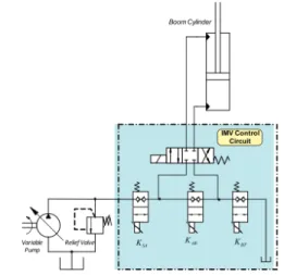
Fig. 1 CIMV system for ELEX
2. Conventional Four IMVs energy saving circuit
In the conventional IMV (CIMV) sketched in Fig.
1,contains four independent proportional valves and
these are driven to follow the trajectory of the
cylinder. Additionally five distinct metering modes
[3] can be observed during operation. These are, (i)
Power Extension mode (PE), (ii) Power Retraction
mode (PR), (iii) High-side Regeneration Extension mode (HSRE), (iv) Low-side Regeneration Extension mode (LSRE), (v) Low-side Regeneration Retraction mode (LSRR). The PE and PR are conceptually the same as the conventional proportional valve control hydraulic system.
However it has benefit of independent metering by minimizing the restriction in the return line which cannot be realized by the proportional control valve.
In HSRE mode, the energy is saved by recirculating the flow in the high pressure side. In the other two modes the fluid recirculates to the low pressure side to save additional energy. For this two modes, check valve is necessary in order to build enough pressure in the CIMV system (Fig.
1). Though, the energy can be saved, on contrary some energy is still unsaved that consumed across the check valve. In addition, CIMV energy saving is lower than expected because of the direct connection between the recirculation flow and supply flow line. In addition CIMV system has four IMV valves that could increase the overall system cost.
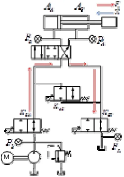
3. New independent metering valve (NIMV) configuration for ELEX
In this section the NIMV circuit is proposed for ELEX system. The schematic diagram of the NIMV has been figured in Fig. 2. As seen in Fig.
2, the proposed circuit consists of three IMV valves and one conventional direction control valves. The entire working mode described in previous section can be achieved by this configuration. On the other hand reducing number of IMV valves means reducing cost and nonlinearities. The three IMV valves can be operated proportionally by controlling the orifice gain K SA , K AB and K BT respectively. It is the task of the direction controlled valve to change the flow direction by fully opened and closing operation.
It should be pointed out that, there is no check valve has been placed throughout the NIMV circuit.
Therefore, it is possible for the proposed circuit to
save the energy loss experienced by the CIMV system across the check valve.Now the different working mode of the NIMV system is studied as follows:
Fig. 2 Proposed NIMV configuration
3.1 Power Extension Mode
The power extension mode is figured in Fig. 3.
As seen, The directional control valve is energized on the left side. The supply oil travels through the SA valve into the head side of the cylinder and the oil forced out from the rod side travels through the BT valve to the return line. In this configuration, SA and BT can be controlled independently same as in the PE mode of CIMV. Thus flow to the tank does not need to be always restricted.
Fig. 3 PE mode ofthe NIMV system
3.2 PR Mode
This working mode is also conceptually same as
the PR of CIMV. Fig 4 displays the NIVM operation in PR mode. Firstly, the directional control valve is energized on the right side. Oil flow from the pump enters into the rod side of the actuator thorough the SA valve and then, the oil in the head side is forced out to the tank through the BT valve. These two valves can be independently controlled. Therefore in this mode, the same controlling capability is available as the power extension mode.
Fig. 4 PR mode of NIMV system
3.3 HSRE Mode
High side regeneration extension mode is quite similar to power extension mode except this mode has energy regenerative capacity. A schematic that describes this mode is shown in Fig 5. In this mode, the directional control valve is energized on the left side and, the other two valves: SA and AB are employed. The supply oil flows through the SA valve to the head side of the cylinder and consequently, the pressurized oil from the rod side of the cylinder is recirculated through the AB valve to the pump high pressure side. Due to the deference between areas of chambers, A and B ( A
A A
B), the flow from chamber B is less than the flow needed for chamber A to obtain certain velocity ( Q
A Q
B). Hence, an additional oil amount is needed from the pump to move the actuator. By doing the recirculation, this HSRE mode has the potential to save energy.
Fig. 5 HSRE mode of NIMV system
3.4 LSRE mode
Fig. 6 displays the operating concept of this mode. This mode is used to handle over running load during lowering. Same as the HSRE, the directional control valve is energized on the left side while the two valves, SA and AB are used to perform this operation. During the actuator extension, the low side generation is performed by circulating the low pressure oil at the rod chamber of the cylinder to its head chamber through valve AB. As discussed in the HSRE mode, the additional flow needs to be supplied by the pump to fulfill the flow requirement due to the cylinder chamber volume difference.
Fig. 6 LSRE mode of NIMV system
3.5 LSRR mode
This mode is applicable for overrunning load, which, for example, happens when lowering a load with gravity assistance. The principle is same as the LSRE mode except the oil flow direction. Here, the directional control valve is energized on the right side(see Fig. 7).
Fig. 7 LSRE mode of NIMV system
The oil flow coming out from the head chamber is circulated through valve AB into the rod chamber t cause the piston to retract. The extra oil flow due to the chamber volume difference then goes to tank through valve BT. This mode has high potential for saving energy because no pump flow is needed. Hence, it is called low side regeneration retraction mode.
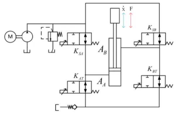
4. Quasi-Static analysis of NIMV
In this section, the quasi static system modeling of the NIMV is carried out. For the system modeling, It is assumed that the system dynamics are relatively slowly changing with respect to the control system. The supply line, return line and different work port capacitances are also ignored.
4.1 PE mode model
A schematic of simplified PE mode is shown in Fig 8. Here the equivalent pressure source is P EQ
and an equivalent valve conductance K EQ . The both active valves are represented as variable orifice restrictions. The valve conductance coefficient K SA
and K BT , can be controlled separately by the controller to obtain independent metering [4]. The flows across the inlet and outlet orifice of the cylinder are given by the following orifice equation.
1
; 0
A SA SA S A A
Q K P K P P A x x (1)
2
; 0
B BT BT B R B
Q K P K P P A x x (2)
Fig. 8 PE mode model
By rearranging Eq. (1) and Eq. (2)
2 2 A
A S
SA
P P Q
K
(3)
2 2 B
B R
BT
P Q P
K
(4) Considering the sum of forces is equal to Fx , the following equation can be written as:
X B B A A
F P A P A (5)
By substituting Eq. (3) and Eq. (4) into the Eq.
(5) we obtain
2 2
2 2
0
A B
S A R B X
SA BT
Q Q
P A P A F
K K
(6)
The following equation is formed after
rearranging the Eq. (6)
3 3 2
2 2
0
A B
S A R B X
SA BT
A A
P A P A x F
K K
(7) By introducing the ratio of areas as Eq. (8) the equivalent valve conductance will be same as Eq.
(9) [4]. That is,
A
B
R A
A
(8)
2 3 2
SA BT EQ
SA BT
K K K
K R K
(9) From Eq. (7), Eq. (8) and Eq. (9) we find,
2 2
2B
0
S R A B
EQ
RP P x A RP P
K
(10) Eq. (10) is then rearranged for getting the Eq.
(11) below
; 0
B B
EQ S A B R
Q xA
K R P P P P x
(11)
By comparing the Eq. (11) term equivalent pressure PEQ is calculated as,
EQ S A B R
P R P P P P (12)
Eq. (12) and Eq. (2) are to be substituted into Eq. (11) leads.
; 0
B EQ EQ B
Q K P xA x (13)
For controlling purpose the velocity represents as commanded velocity, which is represented as x
c; 0
c B B
EQ c
EQ EQ
x A
K Q x
P P
(14)
As both Eq. (13) and Eq. (14) are linearly proportional to the K EQ , Eq. (11) or Eq. (14) can be used for calculating the K EQ . That is:
2 2
_ 2
A B R B
S SET
EQ
RP P P x A
P R RK
(15)
From [3], it is proven that for calculating numerical solution for valve conductance coefficient, the ratio of the area R could be represented as:
SA 3/4
BT
K R
K
(16)
For calculating each valve conductance Eq. (16) is substituted into Eq. (9) and following valve conductance equations are obtained. By using those control equations it is possible to control the opening of the each valve with respect to equivalent pressure and equivalent valve conductance.
3/2 3
SA EQ
K K R R (17)
1
3/2BT EQ
K K R (18)
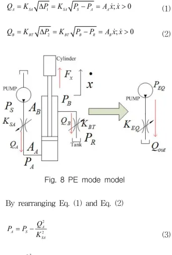
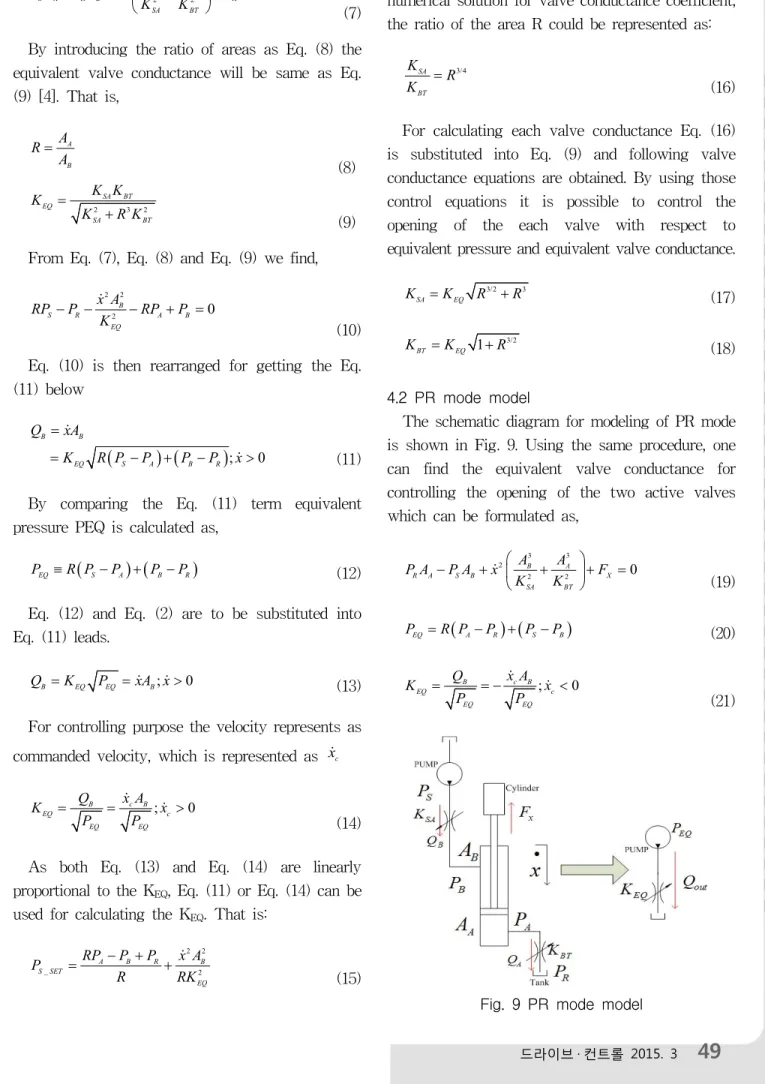
4.2 PR mode model
The schematic diagram for modeling of PR mode is shown in Fig. 9. Using the same procedure, one can find the equivalent valve conductance for controlling the opening of the two active valves which can be formulated as,
3 3
2
2 2
0
B A
R A S B X
SA BT
A A
P A P A x F
K K
(19)
EQ A R S B
P R P P P P (20)
; 0
c B B
EQ c
EQ EQ
x A
K Q x
P P
(21)
Fig. 9 PR mode model
9 2
1
SA EQ
K K R (22)
1/2 3 2
BT EQ
K K R R
(23)
4.3 HSRE mode model
A schematic diagram is shown in Fig. 10 used for modeling the HSRE mode.
Fig. 10 HSRE mode model
Using similar procedure one can find,
3 3 2
2
2 2 2
0
A B A B
S A S B X
SA AB SA
A A A A
P A P A x F
K K K
(24)
EQ S A B S
P R P P P P (25)
; 0
c B B
EQ c
EQ EQ
x A
K Q x
P P
(26)
3/2 3 2
SA EQ
K K R R R (27)
3/2 1/2
AB EQ
1
K K R R (28)
4.4 LSRE mode model
Low side regeneration extension modeling is similar to the high side regeneration extension mode. HSRE is called as LSRE when the load force direction is the same the direction cylinder motion. From the schematic diagram shown in HSRE mode in Fig 10, LSRE mode can be easily modeled. The final valve conductance can be calculated as follows,
; 0
EQ S A B S
B B
EQ A S S B
P R P P P P
Q xA
K R P P P P x
(29)
3/2 3 2
SA EQ
K K R R R (30)
3/2 1/2
AB EQ
1
K K R R (31)
4.5 LSRR mode model
Using a similar type of schematic diagram and quasi-static assumptions simplified Low Side Regeneration Retraction mode can be modeled.Hence, we can easily calculate each acting valve conductance by,
; 0
B B
EQ S A B S
Q xA
K R P P P P x
(32)
EQ S A B S
P R P P P P (33)
9/2 5/2
1
SA EQ
K K R R (34)
3/2 3
AB EQ
K K R
R R (35)
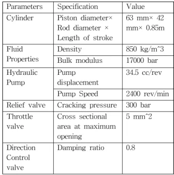
Table 1 System parameters
Parameters Specification Value Cylinder Piston diameter×
Rod diameter × Length of stroke
63 mm× 42 mm× 0.85m
Fluid Properties
Density 850 kg/m^3
Bulk modulus 17000 bar Hydraulic
Pump
Pump displacement
34.5 cc/rev
Pump Speed 2400 rev/min Relief valve Cracking pressure 300 bar Throttle
valve
Cross sectional area at maximum opening
5 mm^2
Direction Control valve
Damping ratio 0.8
5. Simulation results.
The effectiveness of the proposed NIMV
configuration over the CIMV has been carried out
in AMEsim for two energy saving cases: HSRE
mode and LSRR mode. AMEsim is well-known,
powerful software which accepts subprograms developed in other software. In this paper, the NIMV and CIMV hydraulics model has been made in AMEsim using required valve blocks from the AMEsim library.Therefore, the internal dynamics of the different components can be neglected in the current study, as they are routinely built in AMEsim. Additionally, the valve opening dynamics for the two models were coded under the Simulink environment and adopted in AMEsim software.
Finally, the co-simulation AMESim-Simulink model of the New IMV (NIMV) to drive the boom cylinder of the ELEX is shown in Fig. 11, respectively.For each configuration, the setting parameters for the simulations are listed in Table
Fig. 11 Proposed NIMV AMEsim model
0.0 0.1 0.2 0.3
0.0 0.3 0.6 0.9
0.0 0.5 1.0 1.5 2.0 2.5
0 10 20 30
Actuator Speed (m/s)
Ref CIMV NIMV
CIMV NIMV
Displacement (m)
CIMV NIMV
Energy Consumption (kW)
Time(sec)
Fig. 12 HSRE mode simulation
1.The conductances of these valves were defined based on the reference speed and feedback pressure signals Pa, Pb, Ps, and Pr of the hydraulic circuits.
0.0 -0.1 -0.2 -0.3
0.0 0.3 0.6 0.9
0.0 0.5 1.0 1.5 2.0 2.5
0.00 0.02 0.04
Actuator Speed (m/s)
Ref CIMV NIMV
CIMV NIMV
Displacement (m)
CIMV NIMV
Energy Consumption (kW)
Time(sec)
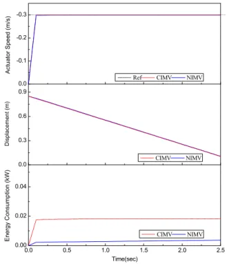
Fig. 13 LSRR mode simulation
Simultaneously, the pump displacement was controlled by a Proportional-Integral-Derivative (PID) controller to save power from the pump.The PID control parameters were determined for each working mode by trial and error. The load conditions are 20 kN for HSRE mode and 15 kN for LSRR mode.
Finally, from the energy consumption comparison between the CIMV and the NIMV configuration (Figs. 12 and 13), it is very clear that the performance of the NIMV configuration is much better that of the CIMV configuration. The NIMV configuration shows 16.43% and 63.63% energy saving performance for HSRE and LSRR, respectively.
6. Conclusion
In this paper, an innovative independent metering
valve based energy saving hydraulic configuration
has been presented for electric excavator.
Mathematical models for different regenerative modes have been developed. To verify the modeling and control equation, a typical hydraulic circuit was built in AMESim. Embedded Matlab programing was used for control purpose. The performance of the new configuration was compared to the four-valveindependent metering system, and the results were positive. As future work, this system can easily be tested by using a high-frequency, on-off hydraulic valve in the electric excavator test rig.
Reference
1) J. I. Yoon, D. Q. Truong, and K. K. Ahn, “A generation step for an electric excavator with a control strategy and verifications of energy consumption”, International Journal of precision engineering and manufacturing, Vol. 14, No 5, pp.755~766, 2013.
2) A. Shenouda, “Quasi-static hydraulic control systems and energy savings potential using independent metering four-valve assembly configuration,” PhD Thesis, Georgia Institute of Technology, 2006.
3) K. Tabor, “Optimal velocity control and cavitation prevention of a hydraulic actuator using four valve independent metering,” SAE Technical Paper, No 2005-01-3620, 2005.
4) N.D. Vaughan, and J.B. Gamble, “The modeling and simulation of a proportional solenoid valve,”
Journal of Dynamics System measurement and Control, Vol. 118, No 1, pp. 120~125, 1996.
[저자 소개]
안경관
E-Mail : [email protected] Tel : 052-259-2282
1990년 서울대학교 기계공학과 졸업(공 학사), 1992년 한국과학기술원 기계공학 과 석사졸업, 1999년 동경공업대학 정밀 기계시스템 박사 과정 졸업. 1992년 삼 성중공업 중장비 사업본부 입사, 2000년~현재 울산대학교 교 수. 유공압시스템의 지능제어, 에너지 회생을 위한 유압시스 템 및 기능성유체를 이용한 새로운 액추에이터의 연구에 종 사. 유공압건설기계학회 편집이사, 제어로봇시스템학회 특임 이사, 대한기계학회, 한국정밀공학회, 제어자동화시스템공학 회, IEEE, 일본기계학회, 일본유공압학회, 일본계측자동제어 학회, 일본 로봇학회 정회원, 공학박사
Dinh Quang Truong
E-mail: [email protected]the B.S degree in the department of Mechanical Engineering from Hochiminh City University of Technology in 2001, and the Ph.D. degree in the School of Mechanical Engineering from University of Ulsan in 2010.
He is currently a Research Professor in the School of Mechanical Engineering, University of Ulsan, Ulsan, Korea. His research interests focus on control theories and applications, fluid power control and energy saving technologies, smart sensors and actuators, renewable energy.
Syed Abu Nahian
E-mail: nahians.cuet@hotm ail.com Joined Chittagong University of Engineering and Technology as Research Assistant in 2010, and became Ph.D candidate in Ulsan University from 2011.
His research interests focus on fluid power control and fault tolerant control.