CopyrightⒸ2014 KSAE / 128-17 pISSN 1225-6382 / eISSN 2234-0149 DOI http://dx.doi.org/10.7467/KSAE.2014.22.2.123 Transactions of KSAE, Vol. 22, No. 2, pp.123-133 (2014)
대형 2행정 디젤기관에 있어서 일체형 전자제어 축압분배 실린더 주유기 시스템의 주유 불균일률에 관한 연구
배 명 환*1)․정 화2)․김 수 민3)․배 창 환4)
경상대학교 기계설계학과1)․한국폴리텍Ⅶ대학 진주캠퍼스 컴퓨터응용기계과2)․
경상대학교 대학원3)․호서대학교 융합대학원4)
A Study on Inequality Rate of Integrated Cylinder Lubricator System with an Accumulated Distribution by the Electronic Control
in a Large Two-stroke Diesel Engine
Myung-whan Bae*1)․Hwa Jung2)․Su-min Kim3)․Chang Hwan Bae4)
1)Department of Mechanical Engineering for Production, Gyeongsang National University, Gyeongnam 660-701, Korea
2)Department of Computer Applied Mechanical, Jinju Campus of Korea PolytechnicVII, Gyeongnam 660-996, Korea
3)Graduate School, Gyeongsang National University, Gyeongnam 660-701, Korea
4)Graduate School of Convergence Technology, Hoseo University, Chungnam 336-795, Korea (Received 6 August 2013 / Revised 12 September 2013 / Accepted 13 September 2013)
Abstract : Minimizing the cylinder wear and the consumption rate of cylinder oil in a large two-stroke diesel engine is
of great economic importance. A motor-driven cylinder lubricator for Sulzer RT-flex large two-stroke diesel engines developed by authors is in need of improving the lubricating system to lubricate cylinder parts optimally by an electronically controlled quill device according to changes of engine load and revolution speed. In order to apply the developed accumulating distributor to an integrated cylinder lubricator by the electronically controlled system as the third research stage, the lubricating system is improved in the electronically controlled quill device with a solenoid valve. In this study, the effects of lubricator revolution speed, driving pressure(or plunger stroke) and cylinder back pressure on oil feed rate and lubrication inequality rate are investigated by using the integrated cylinder lubricator system with an accumulated distribution by the electronic control(I.C.S.), and the oil feed rate and lubrication inequality rate of I.C.S. are compared with those of the motor-driven cylinder lubricator by the electronically controlled quill system equipped with an accumulating distributor(E.D.S.). It is found that the oil feed rate of I.C.S. is smaller than that of E.D.S. due to the reduction of delivery velocity by the higher delivery pressure, and the variances of lubrication inequality rate for I.C.S. have become smaller than those of E.D.S. as the driving pressure in all experimental conditions increases, except for the driving pressure of 26 bar(plunger stroke 2 mm) at the cylinder lubricator speed of 120 rpm.
Key words :
Integrated cylinder lubricator(일체형 실린더 주유기), Large two-stroke diesel engine(대형 2행정 디젤 기관), Oil feed rate (송출유량), Accumulated distribution by the electronic control(전자제어 축압분배), Lubrication inequality(주유 불균일률), Driving pressure(구동압력)
1. 서 론
1)
* Corresponding author, E-mail: [email protected]
2009년 후반기의 글로벌 금융위기로부터 시작하 여 미국·유럽의 재정위기, 세계경제 침체에 대한 불 안감 등이 확산되어 세계적인 경제가 아주 어려움
배명환․정 화․김수민․배창환
에도 불구하고, 국내 조선해양산업은 2010년 후반 기부터 수주량이 일시적으로 증가되어 우리경제에 큰 도움을 주었다. 그러나 1년도 째 지나지 않아 다 시 경제적인 어려움으로 인해 현재 심한 불황을 겪 고 있다. 그래서 지금부터는 단순한 부품조립이나 노동집약 산업의 단계였던 기존 조선산업의 기술력 에서 벗어나 기술집약적인 플로팅 LNG 플랜트, 드 릴쉽 등의 해양에너지 관련 고부가가치 설비사업의 기자재 국산화율 제고를 위한 기술개발에 초점을 맞춰 나아가야 한다.
저자들은 2002년부터 지속적인 순수 국산화 기술 의 연구를 통해 기술집약적 조선기자재 제품 중의 하나인 2행정 디젤기관의 실린더 주유기를 괄목할 만한 수준의 단계까지 개발하였는데,1-9) 개발내용을 3단계로 나누어 요약하면 아래와 같다.
1단계에서는 모형 실린더와 주유기 사이에 실제 적용되는 분배기를 설치하고 주유연결선의 끝단에 장착된 퀼을 전자제어에 의해 조절할 수 있도록 솔 레노이드 밸브를 장착시켜 주유하는 전자제어 퀼 부착 모터구동 실린더 주유기와 분배기 및 개량 전 자제어 퀼 부착 모터구동 실린더 주유기를 개발하 고 특성을 파악하여 성능에 미치는 영향을 조사해
보았다.10-12)
2단계에서는 모형 실린더와 주유기의 사이에 축 압분배기를 설치하고 솔레노이드 밸브에 의한 전자 제어 퀼을 장착시켜 주유하는 축압분배기 부착 전 자 제어식 퀼 시스템 모터구동 실린더 주유기를 개 발하여 최대 토출압력, 최대 송출압력 및 송출유량 을 측정하고 기존의 순차적 정량분배기 부착 기계 식 퀼 시스템과 주유 특성을 비교하여 성능에 미치 는 영향을 파악해 보았다.13)
3단계에서는 축압분배기를 전자제어 주유기에 부착하고 솔레노이드 밸브에 의한 전자제어 퀼을 장착시켜 주유하는 일체형 전자제어 축압분배 실린 더 주유기 시스템을 개발한 다음, 최대 토출압력, 최 대 송출압력 및 송출유량을 측정하고 2단계에서 개 발한 축압분배기 부착 전자제어 퀼 시스템 모터구 동 실린더 주유기와 비교하여 주유 특성을 조사해 보았다.14)
본 연구에서는 대형 2행정 디젤기관의 부하 및 회
전속도의 변화에 따라 실린더에 최적의 주유가 이 루어지도록 3단계에서 개발한 일체형 전자제어 축 압분배 실린더 주유기 시스템을 사용하여 실제기관 의 분위기에 맞도록 질소가스에 의해 모형 실린더 내의 압력을 일정하게 형성시키고 회전속도를 파라 미터로 하여 송출유량을 측정하였다. 실린더 주유 기의 성능에 미치는 영향을 파악하기 위하여 측정 한 송출유량을 2단계에서 개발한 축압분배기 부착 전자제어 퀼 시스템 모터구동 실린더 주유기와 비 교하고 주유 불균일률 특성을 조사하는 것이 본 연 구의 목적이다.
2. 실험 장치 및 방법
2.1 실험장치
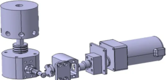
실험에 사용한 일체형 전자제어 축압분배 실린더 주유기 시스템(Integrated Cylinder Lubricator System with an Accumulated Distribution by the Electronic Control ; 이하 I.C.S.라고 칭함.)의 모형도와 제원을 Fig. 1과 Table 1에 나타내고 있다.
본 연구에서 비교한 축압분배기 부착 전자제어 퀼 시스템 모터구동 실린더 주유기 시스템(Motor- driven Cylinder Lubricator System by the Electronical- ly Controlled Quill System Equipped with an Accumu- lating Distributor ; 이하 E.D.S.라고 칭함.)은 저자들 에 의해 2단계에서 개발한 제품으로 1개 실린더 라 이너에 상하 4개씩 총 8개의 주유구가 설치되어있 고 주유구마다 어큐뮬레이터가 각각 장착된 퀼에 의해 주유되는 기존 실린더 주유기에 각 퀼 내 축압 기능을 갖는 다이어프램을 분배기 내의 피스톤 방 식으로 개조하여 압축행정 기간 중 실린더 내 10 ~
Fig. 1 Model of integrated cylinder lubricator system with an accumulated distribution by the electronic control
대형 2행정 디젤기관에 있어서 일체형 전자제어 축압분배 실린더 주유기 시스템의 주유 불균일률에 관한 연구
Table 1 Specifications of the developed integral cylinder lubricator system with an accumulated distribution by the electronic control
Items Specifications
Plunger diameter (mm) 12
Stroke (mm) 20
Discharge point 8
Driving pressure of cylinder lubricator
(bar) 26 ~ 46
Driving voltage (V) 12
Driving system Electronic control
20 bar의 압력에서 전자제어 퀼에 의해 주유할 수 있 도록 하였다.12)
본 연구에서 개발한 I.C.S. 축압분배기는 윤활유 송출구가 8개로 되어 있다. 축압분배기 내 φ 40 mm, 행정 50 mm 피스톤을 설치하여 스프링 탄성계수와 길이의 설정에 따라 주유기의 송출 윤활유에 의해 5 bar 이상에서는 1차 스프링이 8개의 송출구로 오 일을 송출할 수 있도록 하였고, 20 bar 이상에서는 2 차 스프링이 축압기능을 할 수 있도록 하였다.
I.C.S.의 구동은 축압분배기 내에 설치한 압전식 압력계에서 측정된 설정 구동압력 이하일 경우에는 주유기에 부착된 모터에 전자제어장치가 DC 12 V 를 공급하고, 설정 구동압력 이상일 경우에는 전자 제어장치에 의해 전원공급을 중단하여 주유기가 정 지하게 되는데, 구동압력은 디지털 전압조절기에 의해 조정할 수 있다.
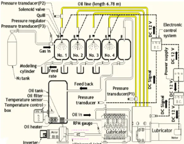
Fig. 2에는 일체형 전자제어 축압분배 실린더 주 유기 시스템 실험장치의 개략도를 보여주고 있다.
직경 100 mm, 높이 50 mm, 두께 50 mm의 모형 실린 더를 아크릴로 제작하여 설치하였는데, 송출된 오 일이 전자제어 퀼에 의해 주유되는 모습을 관찰할 수 있다. 배압은 질소가스에 의해 형성되었고, 주유 기 출구로부터 관 길이 6.78 m 지점의 끝단에는 전 자제어에 의해 작동되는 솔레노이드 밸브를 부착시 켜 윤활유가 개량된 구조의 디젤기관용 퀼에 의해 유효한 기간에 분사될 수 있도록 하였다.
유량 측정시간은 퀼에서 2.5 m 떨어진 지점의 유 관에 타이머가 부착된 솔레노이드 밸브(KSO-G-2B) 를 설치하여 제어하였다. 주유관은 내경 6 mm인 스
Fig. 2 Schematic diagram of experimental apparatus
테인리스 강관을 사용했다.
주유기로 유입되기 전의 윤활유는 오일탱크에 저 장하고, 윤활유의 온도를 높이기 위하여 코일식 전 기히터(3 kW × 2 대)에 의해 가열시켰다. 가열된 윤 활유는 주유기로 공급되어지고 설정온도를 자동적 으로 조절하기 위해 온도센서가 부착된 온도조절기 를 탱크 내에 설치하였다. 또한, 가능한 온도차를 줄 이도록 하기 위해 관 전체를 보온재로 감쌌다.
기존 주유기의 모터회전속도를 측정하기 위해 주 유기 축에 설치된 광센서를 이용한 레이저 회전속 도 측정장치(Pocket tachometer TESTO 465)에 의해 주유기 본체인 플런저 펌프의 회전속도를 측정하였 고, 모터 축과 연결된 인버터(KC-1500A)의 주파수 에 의해 회전속도를 변경시켰다.
2.2 실험방법
Table 2에는 송출유량 측정용 실험조건을 나타내
Table 2 Experimental conditions
Cylinder lubricator motor speed (rpm) 60, 80, 100, 120 Back pressure (bar) 6, 11, 16, 21
Oil pipe length (m) 6.78
Measured spot of maximum discharge
pressure (m) 0.03
Measured spot of maximum delivery
pressure (m) 6.76
Driving pressure of cylinder lubricator
(bar) 26, 31, 36, 41
Control pressure of quill (bar) 6, 11, 16, 21
Myung-whan Bae․Hwa Jung․Su-min Kim․Chang Hwan Bae
고 있다. 윤활유온도는 실제 운전 중인 디젤기관과 유사한 환경설정을 위해 본 실험에서는 자동온도조 절장치에 의해 45℃로 가열하여 사용하였다.
본 연구에 있어서 I.C.S.의 회전속도는 기존의 E.D.S.와 마찬가지로 실제기관 회전속도와 동일한 120, 100, 80 및 60 rpm으로 설정하여 실험을 했다.
실제 대형 2행정 디젤기관은 실린더내의 공기를 압 축하는 과정 중인 10 ~ 20 bar일 때 주유기에서 실 린더 오일이 주유되기 때문에, 본 실험의 모형 실린 더내 배압은 6, 11, 16 및 21 bar로 하였고, 이 때, 주 유기에서 분출되는 압력은 실린더내의 압력보다 높 을 때에만 실린더 오일이 분사되어 윤활유로서의 역할을 할 수 있다. 6 bar는 실린더 오일이 주유될 때 의 실린더내의 압력범위는 아니지만, 이전 연구2-4),
13)와 비교하기 위해 실험조건으로 추가하였다.
본 실험에서는 실제 디젤기관을 사용하지 않고 있기 때문에 실린더내 압력을 측정할 수가 없다. 또 한, I.C.S.는 플런저형이 아니기 때문에 전자제어 퀼 의 작동압력은 파형이 생성되지 않는다. 따라서 주 유 개시점을 판단할 수 없기 때문에 본 연구에서는 Fig. 2에서처럼 기존의 기계식 주유기를 I.C.S.의 옆 에 같이 설치해 놓고 회전속도를 120, 100, 80 및 60 rpm으로 변화시켜 기계식 주유기 주유구 끝단에서 0.03 m 떨어진 지점에 설치한 압전식 압력계로 압력 파형을 측정하고 본 연구의 전자제어 퀼의 작동압 력 파형으로 동일하게 적용하여 규정압력 이상이 되면 전자제어 장치는 퀼에 부착된 솔레노이드 밸 브에 전원이 공급된다.
퀼의 전자제어장치 전원은 DC 12 V로 이 때 설정 된 배압에 해당되는 규정전압은 0.5 V(6 bar), 1 V(11 bar), 1.5 V(16 bar), 2 V(21 bar)이고, 전자제어장치에 설치된 디지털 전압조절장치에 의해 조절된다.
I.C.S.의 경우에는 플런저 펌프를 사용하지 않기 때문에 플런저 행정에 따른 최대 토출 및 송출 압력 과 송출유량을 구할 수가 없다. 따라서 본 연구에서 는 이전 연구7)인 E.D.S.의 연구결과와 비교하기 위 하여 E.D.S.의 배압 16 bar 및 모터회전속도 120 rpm 에서 플런저 행정 2, 4, 6 및 8 mm일 경우의 최대 토 출압력으로 측정된 약 26, 31, 36, 41 bar를 본 연구의 I.C.S.를 구동시키는 압력으로 설정하였다.
주유관 길이가 주유기 성능에 거의 영향을 미치 지 않는다고 하는 것을 이전연구13)에서 밝혔기 때문 에, 본 연구에서는 주유관 길이를 이전 연구2-4)와 동 일한 6.78 m로 하였다.
송출유량은 타이머 부착 솔레노이드 밸브를 이용 하여 120초 동안의 유량을 전자저울(Precisa XT 1220M, 최소 측정단위 0.001 g)로 계량하여 단위시 간당 질량 값으로 나타내었다.
실험에 사용된 실린더 오일은 Mobil Gard 570으 로 주요한 물리적 및 화학적 특성은 저자들의 논문2) 을 참고하기 바란다. 본 연구의 실험에 있어서 주유 기 회전속도의 변동률은 1 rpm 미만이었고, 실린더 의 오일온도 변동률은 2℃ 미만이었다.
3. 실험 결과 및 고찰
3.1 송출유량
Figs. 3 ∼ 6에는 오일온도 45℃에서 E.D.S.의 경 우에는 각 플런저 행정에 있어서, I.C.S.의 경우에는 E.D.S.의 플런저 행정에 해당하는 구동압력에 있어 서 실린더 주유기 회전속도를 120, 100, 80 및 60 rpm 로 변화시켜 배압에 대한 각 모형 실린더의 송출유 량 값을 나타내고 있다.
그림으로부터 실험조건 범위 내에서 I.C.S.와 E.D.S.의 회전속도가 증가할수록 송출유량이 증가 하였고, I.C.S.의 구동압력과 E.D.S.의 플런저 행정 이 증가할수록 송출유량은 증가함을 보여주고 있 다. 또한, 송출유량은 I.C.S.의 구동압력 및 E.D.S. 플 런저 행정에 관계없이 실린더 내의 배압이 증가할 수록 감소하였는데, I.C.S.보다는 E.D.S.의 경우가 감소율이 더 크게 나타났다. 이러한 감소율은 회전 속도가 증가할수록 크게 나타났다.
실제 대형 2행정 디젤기관의 주유압력 범위인 10
~ 20 bar에서 배압의 변화에 대한 I.C.S. 송출유량의 변동폭은 E.D.S.의 경우에 비하여 크지 않음을 알 수 있다. 이것은 본 연구에서 개발한 일체형 전자제어 축압분배 실린더 주유기 시스템의 주요특징으로 최 적 송출유량인지는 추가검토가 필요하지만, 배압이 높을수록 송출유량이 감소되는 단점을 보완할 수 있는 실린더 주유기 시스템임을 알 수 있다.
A Study on Inequality Rate of Integrated Cylinder Lubricator System with an Accumulated Distribution by the Electronic Control in a Large Two-stroke Diesel Engine
5 1 0 1 5 2 0
0 .0 0 .4 0 .8
1 .2 I.C .S . E .D .S . M o d e lin g c y lin d e r N o . 1 M o d e lin g c y lin d e r N o . 2 M o d e lin g c y lin d e r N o . 3 M o d e lin g c y lin d e r N o . 4
Feed rate (kg/h)
P r e s s u r e ( b a r ) 5 1 0 1 5 2 0
0 .0 0 .4 0 .8
1 .2 I.C .S . E .D .S . M o d e lin g c y lin d e r N o . 1 M o d e lin g c y lin d e r N o . 2 M o d e lin g c y lin d e r N o . 3 M o d e lin g c y lin d e r N o . 4
Feed rate (kg/h)
P r e s s u r e (b a r )
(a) Driving pressure 26 bar, plunger stroke 2 mm (b) Driving pressure 31 bar, plunger stroke 4 mm
5 1 0 1 5 2 0
0 .0 0 .4 0 .8
1 .2 I.C .S . E .D .S . M o d e lin g c y lin d e r N o . 1 M o d e lin g c y lin d e r N o . 2 M o d e lin g c y lin d e r N o . 3 M o d e lin g c y lin d e r N o . 4
Feed rate (kg/h)
P r e s s u r e ( b a r ) 5 1 0 1 5 2 0
0 .0 0 .4 0 .8
1 .2 I.C .S . E .D .S . M o d e lin g c y lin d e r N o . 1 M o d e lin g c y lin d e r N o . 2 M o d e lin g c y lin d e r N o . 3 M o d e lin g c y lin d e r N o . 4
Feed rate (kg/h)
P r e s s u r e (b a r )
(c) Driving pressure 36 bar, plunger stroke 6 mm (d) Driving pressure 41 bar, plunger stroke 8 mm Fig. 3 Comparison of feed rate relative to back pressure between the integrated cylinder lubricator system with an accumulated
distribution by the electronic control and the motor-driven cylinder lubricator system by the electronically controlled quill system equipped with an accumulating distributor for four kinds of driving pressure and plunger stroke as a parameter of the respective modeling cylinder at the cylinder lubricator speed of 120 rpm(oil pipe length = 6.78 m, oil temperature = 45℃)
5 1 0 1 5 2 0
0 .0 0 .4 0 .8
1 .2 I.C .S . E .D .S . M o d e lin g c y lin d e r N o . 1 M o d e lin g c y lin d e r N o . 2 M o d e lin g c y lin d e r N o . 3 M o d e lin g c y lin d e r N o . 4
Feed rate (kg/h)
P r e s s u r e ( b a r ) 5 1 0 1 5 2 0
0 .0 0 .4 0 .8
1 .2 I.C .S . E .D .S . M o d e lin g c y lin d e r N o . 1 M o d e lin g c y lin d e r N o . 2 M o d e lin g c y lin d e r N o . 3 M o d e lin g c y lin d e r N o . 4
Feed rate (kg/h)
P r e s s u r e (b a r )
(a) Driving pressure 26 bar, plunger stroke 2 mm (b) Driving pressure 31 bar, plunger stroke 4 mm
5 1 0 1 5 2 0
0 .0 0 .4 0 .8
1 .2 I.C .S . E .D .S . M o d e lin g c y lin d e r N o . 1 M o d e lin g c y lin d e r N o . 2 M o d e lin g c y lin d e r N o . 3 M o d e lin g c y lin d e r N o . 4
Feed rate (kg/h)
P r e s s u r e ( b a r ) 5 1 0 1 5 2 0
0 .0 0 .4 0 .8
1 .2 I.C .S . E .D .S . M o d e lin g c y lin d e r N o . 1 M o d e lin g c y lin d e r N o . 2 M o d e lin g c y lin d e r N o . 3 M o d e lin g c y lin d e r N o . 4
Feed rate (kg/h)
P r e s s u r e (b a r )
(c) Driving pressure 36 bar, plunger stroke 6 mm (d) Driving pressure 41 bar, plunger stroke 8 mm Fig. 4 Comparison of feed rate relative to back pressure between the integrated cylinder lubricator system with an accumulated
distribution by the electronic control and the motor-driven cylinder lubricator system by the electronically controlled quill system equipped with an accumulating distributor for four kinds of driving pressure and plunger stroke as a parameter of the respective modeling cylinder at the cylinder lubricator speed of 100 rpm(oil pipe length = 6.78 m, oil temperature = 45℃)
배명환․정 화․김수민․배창환
5 1 0 1 5 2 0
0 .0 0 .4 0 .8
1 .2 I.C .S . E .D .S . M o d e lin g c y lin d e r N o . 1 M o d e lin g c y lin d e r N o . 2 M o d e lin g c y lin d e r N o . 3 M o d e lin g c y lin d e r N o . 4
Feed rate (kg/h)
P r e s s u r e (b a r ) 5 1 0 1 5 2 0
0 .0 0 .4 0 .8
1 .2 I.C .S . E .D .S . M o d e lin g c y lin d e r N o . 1 M o d e lin g c y lin d e r N o . 2 M o d e lin g c y lin d e r N o . 3 M o d e lin g c y lin d e r N o . 4
Feed rate (kg/h)
P r e s s u r e (b a r )
(a) Driving pressure 26 bar, plunger stroke 2 mm (b) Driving pressure 31 bar, plunger stroke 4 mm
5 1 0 1 5 2 0
0 .0 0 .4 0 .8
1 .2 I.C .S . E .D .S . M o d e lin g c y lin d e r N o . 1 M o d e lin g c y lin d e r N o . 2 M o d e lin g c y lin d e r N o . 3 M o d e lin g c y lin d e r N o . 4
Feed rate (kg/h)
P r e s s u r e (b a r ) 5 1 0 1 5 2 0
0 .0 0 .4 0 .8
1 .2 I.C .S . E .D .S . M o d e lin g c y lin d e r N o . 1 M o d e lin g c y lin d e r N o . 2 M o d e lin g c y lin d e r N o . 3 M o d e lin g c y lin d e r N o . 4
Feed rate (kg/h)
P r e s s u r e (b a r )
(c) Driving pressure 36 bar, plunger stroke 6 mm (d) Driving pressure 41 bar, plunger stroke 8 mm Fig. 5 Comparison of feed rate relative to back pressure between the integrated cylinder lubricator system with an accumulated
distribution by the electronic control and the motor-driven cylinder lubricator system by the electronically controlled quill system equipped with an accumulating distributor for four kinds of driving pressure and plunger stroke as a parameter of the respective modeling cylinder at the cylinder lubricator speed of 80 rpm(oil pipe length = 6.78 m, oil temperature = 45℃)
5 1 0 1 5 2 0
0 .0 0 .4 0 .8
1 .2 I.C .S . E .D .S . M o d e lin g c y lin d e r N o . 1 M o d e lin g c y lin d e r N o . 2 M o d e lin g c y lin d e r N o . 3 M o d e lin g c y lin d e r N o . 4
Feed rate (kg/h)
P r e s s u r e (b a r ) 5 1 0 1 5 2 0
0 .0 0 .4 0 .8
1 .2 I.C .S . E .D .S . M o d e lin g c y lin d e r N o . 1 M o d e lin g c y lin d e r N o . 2 M o d e lin g c y lin d e r N o . 3 M o d e lin g c y lin d e r N o . 4
Feed rate (kg/h)
P r e s s u r e (b a r )
(a) Driving pressure 26 bar, plunger stroke 2 mm (b) Driving pressure 31 bar, plunger stroke 4 mm
5 1 0 1 5 2 0
0 .0 0 .4 0 .8
1 .2 I.C .S . E .D .S . M o d e lin g c y lin d e r N o . 1 M o d e lin g c y lin d e r N o . 2 M o d e lin g c y lin d e r N o . 3 M o d e lin g c y lin d e r N o . 4
Feed rate (kg/h)
P r e s s u r e (b a r ) 5 1 0 1 5 2 0
0 .0 0 .4 0 .8
1 .2 I.C .S . E .D .S . M o d e lin g c y lin d e r N o . 1 M o d e lin g c y lin d e r N o . 2 M o d e lin g c y lin d e r N o . 3 M o d e lin g c y lin d e r N o . 4
Feed rate (kg/h)
P r e s s u r e (b a r )
(c) Driving pressure 36 bar, plunger stroke 6 mm (d) Driving pressure 41 bar, plunger stroke 8 mm Fig. 6 Comparison of feed rate relative to back pressure between the integrated cylinder lubricator system with an accumulated
distribution by the electronic control and the motor-driven cylinder lubricator system by the electronically controlled quill system equipped with an accumulating distributor for four kinds of driving pressure and plunger stroke as a parameter of the respective modeling cylinder at the cylinder lubricator speed of 60 rpm(oil pipe length = 6.78 m, oil temperature = 45℃)
대형 2행정 디젤기관에 있어서 일체형 전자제어 축압분배 실린더 주유기 시스템의 주유 불균일률에 관한 연구
5 1 0 1 5 2 0
- 1 0 - 5 0 5 1 0
Inequality rate (%)
B a c k p r e s s u r e (b a r )
I.C .S . E .D .S . M o d e lin g c y lin d e r N o . 1 M o d e lin g c y lin d e r N o . 2 M o d e lin g c y lin d e r N o . 3 M o d e lin g c y lin d e r N o . 4
5 1 0 1 5 2 0
- 1 0 - 5 0 5 1 0
Inequality rate (%)
B a c k p r e s s u r e (b a r )
I.C .S . E .D .S . M o d e lin g c y lin d e r N o . 1 M o d e lin g c y lin d e r N o . 2 M o d e lin g c y lin d e r N o . 3 M o d e lin g c y lin d e r N o . 4
(a) Driving pressure 26 bar, plunger stroke 2 mm (b) Driving pressure 31 bar, plunger stroke 4 mm
5 1 0 1 5 2 0
- 1 0 - 5 0 5 1 0
Inequality rate (%)
B a c k p r e s s u r e (b a r )
I.C .S . E .D .S . M o d e lin g c y lin d e r N o . 1 M o d e lin g c y lin d e r N o . 2 M o d e lin g c y lin d e r N o . 3 M o d e lin g c y lin d e r N o . 4
5 1 0 1 5 2 0
- 1 0 - 5 0 5 1 0
Inequality rate (%)
B a c k p r e s s u r e (b a r )
I.C .S . E .D .S . M o d e lin g c y lin d e r N o . 1 M o d e lin g c y lin d e r N o . 2 M o d e lin g c y lin d e r N o . 3 M o d e lin g c y lin d e r N o . 4
(c) Driving pressure 36 bar, plunger stroke 6 mm (d) Driving pressure 41 bar, plunger stroke 8 mm Fig. 7 Comparison of lubrication inequality rate relative to back pressure between the integrated cylinder lubricator system with an
accumulated distribution by the electronic control and the motor-driven cylinder lubricator system by the electronically controlled quill system equipped with an accumulating distributor for four kinds of driving pressure and plunger stroke as a parameter of the respective modeling cylinder at the cylinder lubricator speed of 120 rpm(oil pipe length = 6.78 m, oil temperature = 45℃)
본 연구의 I.C.S.는 이전 E.D.S.보다도 동일한 실 험조건에서 송출유량이 적게 나타나고 있는데, 송 출유량이 적다고 하는 것은 윤활유 소비량이 감소 되었기 때문에 바람직하지만, 실린더 내의 최적 윤 활조건에 맞는 송출유량인지에 대해서는 파악할 수 없기 때문에 추후의 연구에서 검토가 필요하다.
그림에서 I.C.S. 및 E.D.S. 모두 배압이 증가할수 록 송출유량이 감소하는 것은 송출속도가 작아지고 주유기간이 상대적으로 짧아지기 때문이고, 플런저 행정 및 구동압력이 커질수록 송출유량이 증가하는 것은 송출체적이 증가되기 때문이다. 또한 실린더 주유기 회전속도가 커지면 송출속도도 커지므로 송 출유량은 증가한다.11)
한편, I.C.S.의 경우에는 토출 및 송출 압력 모두 E.D.S.의 경우보다 높기 때문에 송출속도가 작아져 송출유량이 감소되었고, 배압에 따른 토출 및 송출 압력의 변화가 거의 없기 때문에 배압에 의한 송출 유량의 변화도 상대적으로 낮게 나타났다.
3.2 주유 불균일률
Figs. 7 ∼ 10에는 Figs. 3 ∼ 6에서 측정한 각 모형 실린더의 송출유량에 대한 편차를 파악하기 위해 I.C.S.와 E.D.S.의 주유 불균일률을 비교하여 나타내 고 있다. 여기서 주유 불균일률은 축압분배기의 각 분배구에서 각 실린더로 토출되는 송출유량의 균일 성을 알아보기 위한 척도값으로, 4개 실린더의 주유 량 평균값을 기준으로 하여 각 실린더의 송출유량 과의 차로서 정의를 내려 다음과 같이 산출하였다.
주유 불균일률 평균 송출유량
송출유량 평균 송출유량
×
Fig. 7은 주유기 회전속도가 120 rpm일 때 I.C.S.의 각 구동압력과 E.D.S.의 각 플런저 행정에 있어서 각 모형 실린더에 대한 주유 불균일률을 나타낸 것 으로 실린더 배압의 증가 따른 I.C.S.의 주유 불균일 률 변화폭이 -1.41 ~ 2.35%이고, E.D.S.의 경우는 -1.67 ~ 1.33%로 I.C.S.의 주유 불균일률 변화폭이 약
Myung-whan Bae․Hwa Jung․Su-min Kim․Chang Hwan Bae
5 1 0 1 5 2 0
- 1 0 - 5 0 5 1 0
Inequality rate (%)
B a c k p r e s s u r e (b a r )
I.C .S . E .D .S . M o d e lin g c y lin d e r N o . 1 M o d e lin g c y lin d e r N o . 2 M o d e lin g c y lin d e r N o . 3 M o d e lin g c y lin d e r N o . 4
5 1 0 1 5 2 0
- 1 0 - 5 0 5 1 0
Inequality rate (%)
B a c k p r e s s u r e (b a r )
I.C .S . E .D .S . M o d e lin g c y lin d e r N o . 1 M o d e lin g c y lin d e r N o . 2 M o d e lin g c y lin d e r N o . 3 M o d e lin g c y lin d e r N o . 4
(a) Driving pressure 26 bar, plunger stroke 2 mm (b) Driving pressure 31 bar, plunger stroke 4 mm
5 1 0 1 5 2 0
- 1 0 - 5 0 5 1 0
Inequality rate (%)
B a c k p r e s s u r e (b a r )
I.C .S . E .D .S . M o d e lin g c y lin d e r N o . 1 M o d e lin g c y lin d e r N o . 2 M o d e lin g c y lin d e r N o . 3 M o d e lin g c y lin d e r N o . 4
5 1 0 1 5 2 0
- 1 0 - 5 0 5 1 0
Inequality rate (%)
B a c k p r e s s u r e (b a r )
I.C .S . E .D .S . M o d e lin g c y lin d e r N o . 1 M o d e lin g c y lin d e r N o . 2 M o d e lin g c y lin d e r N o . 3 M o d e lin g c y lin d e r N o . 4
(c) Driving pressure 36 bar, plunger stroke 6 mm (d) Driving pressure 41 bar, plunger stroke 8 mm Fig. 8 Comparison of lubrication inequality rate relative to back pressure between the integrated cylinder lubricator system with an
accumulated distribution by the electronic control and the motor-driven cylinder lubricator system by the electronically controlled quill system equipped with an accumulating distributor for four kinds of driving pressure and plunger stroke as a parameter of the respective modeling cylinder at the cylinder lubricator speed of 100 rpm(oil pipe length = 6.78 m, oil temperature = 45℃)
간 더 크게 나타났지만, 실린더 주유기 회전속도 120 rpm의 구동압력 26 bar(플런저 행정 2 mm)인 경 우를 제외하면 구동압력(플런저 행정)이 증가할수 록 I.C.S. 주유 불균일률의 변화폭도 작아지고 있음 을 알 수 있다.
Figs. 8, 9 및 10은 실린더 주유기 회전속도 100, 80 및 60 rpm일 경우의 실린더 배압에 따른 각 모형 실 린더 주유 불균일률값을 보여주고 있다. Fig. 8의 100 rpm에서는 I.C.S.의 주유 불균일률 변화폭이 -1.79 ~ 2.51이고, E.D.S.의 경우는 -2.50 ~ 1.97%로 나타났고, Fig. 9의 80 rpm에서는 I.C.S.의 주유 불균 일률 변화폭이 -1.93 ~ 2.82%이고, E.D.S.의 경우는 -4.40 ~ 2.77%로 나타났으며, Fig. 10의 60 rpm에서 는 I.C.S.의 주유 불균일률 변화폭이 -2.09 ~ 3.04%이 고, E.D.S.의 경우는 -5.82 ~ 3.81%로 나타나 실린더 주유기 회전속도가 작아질수록 I.C.S.에 비해 E.D.S.
의 주유 불균일률 변화폭이 더 크게 나타나고 있음 을 알 수 있다.
Figs. 7 ∼ 10에서 실린더 주유기 회전속도 120 rpm의 구동압력 26 bar(플런저 행정 2 mm)를 제외하 면 모든 실험조건에서 E.D.S.의 주유 불균일률 변화 폭이 I.C.S.이 경우보다도 최대 약 1.88배 높게 나타 남을 알 수 있다.
또한, 그림에서 I.C.S.의 경우에 동일한 실린더 주 유기 회전속도, 구동압력 및 모형 실린더에서 실린 더 배압이 6 bar에서 21 bar까지 증가하여도 주유 불 균일률값은 거의 변화하지 않고, 동일한 실린더 주 유기 회전속도에서 구동압력이 증가할수록 주유 불 균일률 변화폭이 작아지고 있다. 반면에 E.D.S.에서 는 실린더 주유기 회전속도가 증가할수록 주유 불 균일률 변화폭이 작아지고, 동일한 실린더 주유기 회전속도에서 배압이 증가할수록 주유 불균일률 변 화폭이 작아짐을 알 수 있다.
I.C.S.는 실린더 주유기에 일체형으로 축압분배 기가 부착되어 있어 주유기에서 송출된 오일은 맥 동이 제거되고, 토출압력인 주유기 구동압력이 축
A Study on Inequality Rate of Integrated Cylinder Lubricator System with an Accumulated Distribution by the Electronic Control in a Large Two-stroke Diesel Engine
5 1 0 1 5 2 0
- 1 0 - 5 0 5 1 0
Inequality rate (%)
B a c k p r e s s u r e (b a r )
I.C .S . E .D .S . M o d e lin g c y lin d e r N o . 1 M o d e lin g c y lin d e r N o . 2 M o d e lin g c y lin d e r N o . 3 M o d e lin g c y lin d e r N o . 4
5 1 0 1 5 2 0
- 1 0 - 5 0 5 1 0
Inequality rate (%)
B a c k p r e s s u r e (b a r )
I.C .S . E .D .S . M o d e lin g c y lin d e r N o . 1 M o d e lin g c y lin d e r N o . 2 M o d e lin g c y lin d e r N o . 3 M o d e lin g c y lin d e r N o . 4
(a) Driving pressure 26 bar, plunger stroke 2 mm (b) Driving pressure 31 bar, plunger stroke 4 mm
5 1 0 1 5 2 0
- 1 0 - 5 0 5 1 0
Inequality rate (%)
B a c k p r e s s u r e (b a r )
I.C .S . E .D .S . M o d e lin g c y lin d e r N o . 1 M o d e lin g c y lin d e r N o . 2 M o d e lin g c y lin d e r N o . 3 M o d e lin g c y lin d e r N o . 4
5 1 0 1 5 2 0
- 1 0 - 5 0 5 1 0
Inequality rate (%)
B a c k p r e s s u r e (b a r )
I.C .S . E .D .S . M o d e lin g c y lin d e r N o . 1 M o d e lin g c y lin d e r N o . 2 M o d e lin g c y lin d e r N o . 3 M o d e lin g c y lin d e r N o . 4
(c) Driving pressure 36 bar, plunger stroke 6 mm (d) Driving pressure 41 bar, plunger stroke 8 mm Fig. 9 Comparison of lubrication inequality rate relative to back pressure between the integrated cylinder lubricator system with an
accumulated distribution by the electronic control and the motor-driven cylinder lubricator system by the electronically controlled quill system equipped with an accumulating distributor for four kinds of driving pressure and plunger stroke as a parameter of the respective modeling cylinder at the cylinder lubricator speed of 80 rpm(oil pipe length = 6.78 m, oil temperature = 45 ℃)
5 1 0 1 5 2 0
- 1 0 - 5 0 5 1 0
Inequality rate (%)
B a c k p r e s s u r e (b a r )
I.C .S . E .D .S . M o d e lin g c y lin d e r N o . 1 M o d e lin g c y lin d e r N o . 2 M o d e lin g c y lin d e r N o . 3 M o d e lin g c y lin d e r N o . 4
5 1 0 1 5 2 0
- 1 0 - 5 0 5 1 0
Inequality rate (%)
B a c k p r e s s u r e (b a r )
I.C .S . E .D .S . M o d e lin g c y lin d e r N o . 1 M o d e lin g c y lin d e r N o . 2 M o d e lin g c y lin d e r N o . 3 M o d e lin g c y lin d e r N o . 4
(a) Driving pressure 26 bar, plunger stroke 2 mm (b) Driving pressure 31 bar, plunger stroke 4 mm
5 1 0 1 5 2 0
- 1 0 - 5 0 5 1 0
Inequality rate (%)
B a c k p r e s s u r e (b a r )
I.C .S . E .D .S . M o d e lin g c y lin d e r N o . 1 M o d e lin g c y lin d e r N o . 2 M o d e lin g c y lin d e r N o . 3 M o d e lin g c y lin d e r N o . 4
5 1 0 1 5 2 0
- 1 0 - 5 0 5 1 0
Inequality rate (%)
B a c k p r e s s u r e (b a r )
I.C .S . E .D .S . M o d e lin g c y lin d e r N o . 1 M o d e lin g c y lin d e r N o . 2 M o d e lin g c y lin d e r N o . 3 M o d e lin g c y lin d e r N o . 4
(c) Driving pressure 36 bar, plunger stroke 6 mm (d) Driving pressure 41 bar, plunger stroke 8 mm Fig. 10 Comparison of lubrication inequality rate relative to back pressure between the integrated cylinder lubricator system with an
accumulated distribution by the electronic control and motor-driven cylinder lubricator system by the electronically controlled quill system equipped with an accumulating distributor for four kinds of driving pressure and plunger stroke as a parameter of the respective modeling cylinder at the cylinder lubricator speed of 60 rpm(oil pipe length = 6.78 m, oil temperature = 45 ℃)
배명환․정 화․김수민․배창환
압분배기 내의 압력과 거의 일정하게 유지되어 이 압력이 바로 전자제어 퀼에 전달되고 있기 때문에 E.D.S.에 비해 실린더 배압에 따른 압력손실이 적어 각 실린더의 주유 불균일률값 및 변화폭이 대체적 으로 작은 반면, E.D.S.는 실린더 주유기의 플런저 펌프에서 송출된 윤활유가 맥동이 발생되어 주유기 와 퀼의 중간에 설치된 축압분배기에 의해 윤활유 압력을 일정하게 유지시키지만, 접촉면적이 많아 점성저항이 증가되어 주유 불균일률값이 높게 나타 났다고 판단된다.
4. 결 론
본 연구에서는 저자들이 독자적으로 개발한 대형 2행정 디젤기관용 일체형 전자제어 축압분배 실린 더 주유기 시스템을 사용하여 모형 실린더에 배압 을 걸어 주유시스템의 송출유량 및 주유 불균일률 특성을 조사하고, 2단계에서 개발한 축압분배기 부 착 전자제어 퀼 시스템 모터구동 실린더 주유기와 비교하여 다음과 같은 주요결과를 얻었다.
1) 동일 실험조건에서 일체형 전자제어 축압분배 실린더 주유기 시스템(I.C.S.)은 축압분배기 부착 전 자제어 퀼 시스템 모터구동 실린더 주유기 시스템 (E.D.S.)보다 송출압력이 더 크기 때문에 송출속도 의 감소로 인해 송출유량은 적었다.
2) 실험조건 범위 내에서 I.C.S.와 E.D.S.는 회전속 도 및 구동압력(플런저 행정)이 증가할수록 송출유 량이 증가하였다. 그러나 송출유량은 실린더 배압 이 증가할수록 감소하였는데, I.C.S.보다는 E.D.S.의 경우가 감소율이 더 크게 나타났다.
3) 실린더 주유기 회전속도 120 rpm의 구동압력 26 bar(플런저 행정 2 mm)인 경우를 제외하면 모든 실험조건에서 구동압력(플런저 행정)이 증가할수 록 I.C.S.의 주유 불균일률 변화폭이 작아졌다.
4) I.C.S.는 동일한 실린더 주유기 회전속도, 구동 압력 및 모형 실린더에서 실린더 배압이 증가하여 도 주유 불균일률값은 거의 변화하지 않았고, 동일 한 실린더 주유기 회전속도에서 구동압력이 증가할 수록 주유 불균일률 변화폭이 작아졌다. 반면에 E.D.S.에서는 실린더 주유기 회전속도가 증가할수
록 주유 불균일률 변화폭이 작아졌고, 동일한 실린 더 주유기 회전속도에서 배압이 증가할수록 주유 불균일률 변화폭이 작아졌다.
후 기
본 연구는 2단계 BK21사업단(첨단기계항공고급 인력양성사업단) 및 공학연구원의 지원을 받아 수 행되었기에 도움을 주신 관계자 여러분께 감사드린 다.
References
1) M. W. Bae, “Present Development Situation of Cylinder Lubricator in a Large Two-stroke Marine Diesel Engine,” Ship's Machinery 2004, Korea Marine Equipment Association, pp.45- 62, 2004.
2) M. W. Bae, H. Jung and H. J. Ok, “A Study on Effect of Cylinder Back Pressure upon Feed Rate and Delivery Characteristics of Motor- driven Lubricator in a Large Two-stroke Diesel Engine,” Transactions of KSAE, Vol.13, No.5, pp.19-28, 2005.
3) M. W. Bae, H. Jung, H. J. Ok and Y. Mochi- maru, “The Effect of Back Pressure on Perfor- mance of Motor-driven Cylinder Lubricator in a Large Two-stroke Marine Diesel Engine,”
Proceedings of the 7th International Sympo- sium on Marine Engineering ISME TOKYO 2005 (ISME 2005-32-4), pp.1-7 (CD), 2005.
4) M. W. Bae, H. Jung, H. J. Ok, I. D. Kim and Y.
Mochimaru, “Effect of Quill Accumulator upon Performance of Motor-driven Cylinder Lubricator in a Large Two-stroke Diesel Engine,” Procee- dings of the 18th Internal Combustion Engine International Symposium (Society of Automo- tive Engineers of Japan, Inc. JSAE), pp.1-6 (CD), 2005.
5) M. W. Bae, H. J. Ok and H. Jung, “A Study on Effect of Quill Accumulator upon Performance of Motor-driven Cylinder Lubricator Cylinder in a Large Two-stroke Diesel Engine,” Trans- actions of KSAE, Vol.15, No.2, pp.115-125,
대형 2행정 디젤기관에 있어서 일체형 전자제어 축압분배 실린더 주유기 시스템의 주유 불균일률에 관한 연구
2007.
6) S. Baba, H. Tanaka and T. Kobayashi, “Elec- tronically Controlled Cylinder Lubrication System,” Journal of the Japan Institution of Marine Engineering, Vol.37, No.12, pp.29-33, 2002.
7) T. Jensen, “Swirl Injection Lubrication Low Cylinder Oil Consumption without Sacrificing Wear Rates,” Journal of the Japan Institution of Marine Engineering, Vol.37, No.2, pp.41-50, 2002.
8) M. Tanaka, “Improved Cylinder Lubricator,”
Journal of the Japan Institution of Marine Engineer- ing, Vol.37, No.2, pp.32-40, 2002.
9) K. Sakaguchi and T. Yamamoto, “Latest Deve- lopments in Cylinder Lubricating Systems,”
Journal of the Japan Institution of Marine Engineering, Vol.40, No.2, pp.72-77, 2005.
10) M. W. Bae, H. Jung, I. D. Kim and C. H. Kang,
“Feed Rate Characteristics of Motor-driven Cylinder Lubricator with Distributer and Elec- tronic Control Quill in a Large Two-stroke Diesel Engine,” KSAE Spring Conference Proceedings, pp.426-432, 2006.
11) M. W. Bae, H. Jung, Y. H. Jung, I. D. Kim and C. H. Kang, “Performance Characteristics of Motor-driven Cylinder Lubricator with Distri-
buter and Improved Electronic Control Quill in a Large Two-stroke Diesel Engine,” KSAE Fall Conference Proceedings, pp.213-219, 2006.
12) M. W. Bae, H. Jung and C. H. Bae, “Charac- teristics of Lubrication Inequality Rate for a Motor-driven Cylinder Lubricator by the Elec- tronically Controlled Quill System Equipped with an Accumulating Distributor in a Large Two-stroke Diesel Engine,” Proceedings of the Third International Symposium on Mechanics, Aerospace and Informatics Engineering 2009 (ISMAI-03 2009), pp.442-450, 2009.
13) M. W. Bae, H. Jung, M. H. Ahn, K. H. Kyung, Y. K. Kim and Y. Mochimaru, “Feed Rate Characteristics of Cylinder Lubricator Driven by Motor in a Large Two-stroke Marine Diesel Engine,” Proceedings of the Korea Conference on Liquid Atomization and Spray Systems, pp.102-111, 2003.
14) M. W. Bae, H. Jung and C. H. Bae, “A Study on Feed Rate Characteristics of Motor-driven Cylinder Lubricator by the Electronically Controlled Quill System Equipped with an Accumulating Distributor in a Large Two-stroke Diesel Engine,” Transactions of KSAE, Vol.19, No.4, pp.115-125, 2007.