Ⅰ. INTRODUCTION
The introduction of nickel-titanium (Ni-Ti) rotary instruments has transformed root canal preparation. Nickel-titanium rotary instruments
* Corresponding author: Kee-Yeon Kum
Dept. of Conservative Dentistry, Dental Research Institute, College of Dentistry, Seoul National University
Yungun-Dong 28, Jongro-Gu Seoul, 110-749, Korea Tel: 82-2-2072-2656 Fax: 82-2-2072-3859 E-mail: [email protected]
The Effect of Surface Defects on the Cyclic Fatigue Fracture of
HEROShaper Ni-Ti rotary files in a Dynamic Model: A Fractographic Analysis
Jung-Kyu Lee1, Eui-Sung Kim1, Myoung-Whai Kang2, Kee-Yeon Kum2*
1,2Department of Conservative Dentistry, 1Oral Science Research Center,
2Dental Research Institute, 1Yonsei University, 2Seoul National University ABSTRACT
This in vitro study examined the effect of surface defects on cutting blades on the extent of the cyclic fatigue fracture of HEROShaper Ni-Ti rotary files using fractographic analysis of the fractured surfaces. A total of 45 HEROShaper (MicroMega) Ni-Ti rotary files with a #30/.04 taper were divid- ed into three groups of 15 each. Group 1 contained new HEROShapers without any surface defects.
Group 2 contained HEROShapers with manufacturing defects such as metal rollover and machining marks. Group 3 contained HEROShapers that had been clinically used for the canal preparation of 4-6 molars. A fatigue-testing device was designed to allow cyclic tension and compressive stress on the tip of the instrument whilst maintaining similar conditions to those experienced in a clinic. The level of fatigue fracture time was measured using a computer connected the system. Statistical analysis was performed using a Tukey’s test. Scanning electron microscopy (SEM) was used for fractographic analysis of the fractured surfaces. The fatigue fracture time between groups 1 and 2, and between groups 1 and 3 was significantly different (p < 0.05) but there was no significant differ- ence between groups 2 and 3 (p > 0.05). A low magnification SEM views show brittle fracture as the main initial failure mode. At higher magnification, the brittle fracture region showed clusters of fatigue striations and a large number of secondary cracks. These fractures typically led to a central region of catastrophic ductile failure. Qualitatively, the ductile fracture region was characterized by the formation of microvoids and dimpling. The fractured surfaces of the HEROShapers in groups 2 and 3 were always associated with pre-existing surface defects. Typically, the fractured surface in the brittle fracture region showed evidence of cleavage (transgranular) facets across the grains, as well as intergranular facets along the grain boundaries. These results show that surface defects on cutting blades of Ni-Ti rotary files might be the preferred sites for the origin of fatigue fracture under experimental conditions. Furthermore, this work demonstrates the utility of fractography in evaluating the failure of Ni-Ti rotary files. [J Kor Acad Cons Dent 32(2):130-137, 2007]
Key words: Surface defect, Fatigue fracture, Ductile fracture, Striation, HEROShaper, Fracto- graphic analysis
- Received 2006.12.20., revised 2007.1.8., accepted 2007.1.19. -
exhibit super-elasticity and can prepare root canals with less apical aberrations and with an excellent taper and flow compared with stainless steel hand files1-3). Despite the evident advan- tages, Ni-Ti rotary instruments can undergo unexpected fracture below the elastic limit of the alloy as a result of flexural fatigue or torsional stress in the curved root canal4-7). Many factors have been implicated in the fatigue fracture of Ni- Ti rotary instruments. Of these factors, the root canal geometry (including the radius and angle of curvature), rotation speed (rpm), instrumentation force, and instrument design (diameter, taper, and cross-sectional configuration) were found to be more significant4,8-14). The surface quality can also be an important factor in fatigue fracture.
Recent studies using scanning electron microscopy have revealed the presence of micro-fissures, machining marks, metal strips, pits, and blunt cutting edges on the surface of both new and used Ni-Ti rotary instruments16-20). These surface defects may initiate microcracks and play a role in the fatigue failure of instruments21). However, there is little knowledge of the potential role of surface defects on the fatigue failure or the true mode of failure involved. Several studies on cyclic fatigue have been carried out using a dynamic model incorporating axial movement15,16,22). This provides a better simulation of the clinical envi- ronment. However, there are no reports in the dental literature showing an evaluation of the cyclic fatigue of HEROShaper. Fractography can be broadly defined as the science of observing, measuring and interpreting a fractured surface topography23). When material failure involves actual breakage, fractography can be used to identify the fracture origin, the direction of crack propagation, the failure mechanism, materials defects, and the nature of the stresses24).
The aim of this in vitro study was to examine the fractured surface of HEROShaper files that were fractured experimentally by cyclic fatigue stress in a dynamic model using scanning electron microscopy. An additional aim was to evaluate the effect of surface defects left on the instruments on the fatigue fracture using fractographic analysis.
Ⅱ. MATERIALS & METHODS
Materials: A total of 45 HEROShaper (Micro- Mega, Becanson, France) rotary files were used in this study. All the files were 21 ㎜ in length and had a #30/.04 taper. The files were divided into three groups containing 15 in each: Group 1, new HEROShaper rotary files without any surface defects; Group 2, HEROShaper rotary files with manufacturing defects such as metal rollover, microcracks and machining marks; and Group 3, HEROShaper rotary files that had been used for the root canal preparation of 4-6 molars. All the HEROShapers used in this study were supplied by MicroMega Company (Becanson, France).
E
Exxppeerriimmeennttaall DDeessiiggnn:: The fatigue-testing device (ENDO TESTER™, Denbotix, Bucheon, Korea) was designed to allow cyclic tension and compressive stress on the tip of the instrument whilst maintaining similar conditions to those encountered in clinical situations (Figure 1). In addition, the device could be programmed to auto- matically control the rotation speed (300 rpm), pecking distance (6 ㎜), and pecking speed (1 ㎜ /sec). A sloped metal block was fixed to 15�and had a 2 ㎜ notched V-form to guide the instru- ments. The angle of curvature, which was calcu- lated using the Schneider’s method25), was 50�at a 6 ㎜ pecking distance. During the tests, friction was minimized using GlydeTM (FILE PREP, Maillefer, Dentsply, Ballaigues, Switzerland) as a lubricant. Fracture was detected early because the tip of the instrument was visible at the end of the curve of the radii. The time elapsed before fracture was measured using a computer program connected to the system. The files were cleaned ultrasonically in alcohol for approximately 60 sec- onds prior to the scanning electron microscopy (S- 800 SEM Hitachi FE SEM, Tokyo, Japan) exami- nation in order to remove any surface debris from the surface. The SEM observations were made after drying and ion-coating the sample with Eiko IB-C to a 20 - 30 ㎚ thickness. Fractographic analysis was performed by initially surveying the entire fractured surface at low magnification (×
200 and 500). This usually showed one or more
areas where the fracture appeared to have origi- nated. These areas were then observed at higher magnifications (× 3000, 5000, and 10,000) to examine the surface features that are consistent with the different types of failure (i.e., brittle fracture, fatigue crack growth, or ductile frac- ture). To determine the statistical difference between the different groups, data obtained was subjected to a Tukey’s test. The significance was determined at the 95% confidence level.
Ⅲ. RESULTS 1. Resistance to cyclic fatigue
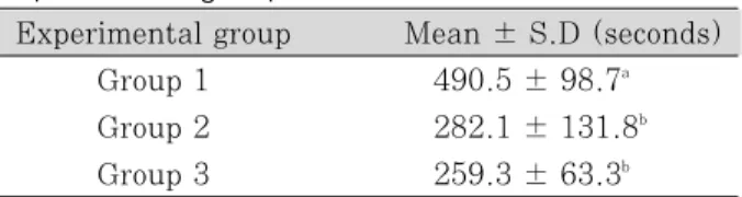
Table 1 shows the mean fracture time for each group. There was a significant difference in the fracture time between groups 1 and 2, and between groups 1 and 3 (p < 0.05). However, there was no significant difference between groups 2 and 3 (p > 0.05).
2. Fractographic analysis on the fracture surface
Microphotographs of the lateral surface of HEROShapers in group 2 showed metal rollover and/or significant machining marks along the faces of the flutes (Figure 2). In contrast, the lat- eral surfaces of the new HEROShaper files were rather clean and flawless. The low-magnification
(× 200 and × 500) SEM images show small areas of brittle fracture located on the edge of the cross section of the fractured instruments, which typically leads to a large central fibrous area of catastrophic ductile fracture. The higher magnifi- cation view (× 3000 and × 10,000) revealed clusters of fatigue striations and a large number of secondary cracks in the brittle fracture area (Figure 3), which confirmed that the instruments failed as a result of fatigue. Transgranular frac- ture across the grains as well as intergranular fracture along the grain boundaries was also observed in the brittle fracture area. The ductile fracture area was characterized by the typical for- mation of microvoids and the dimpling (cup-and- cone fracture), particularly elongated dimples in some specimens in group 3 (Figure 4a). All the fractured surfaces of HEROShapers in groups 2 and 3 were always consistent with the slow crack propagation (in a brittle fracture mode) from pre- existing surface defects (Figure 4b). Voids or regions of separation between some grains are also evident.
Table 1. Mean fatigue fracture time for the three experimental groups
Experimental group Mean ± S.D (seconds)
Group 1 490.5 ± 98.7a
Group 2 282.1 ± 131.8b Group 3 259.3 ± 63.3b
* Groups with statistically significant differences are indicated by the different letters (Tukey’s Test, p < 0.05).
Figure 1. Schematic diagram of the fatigue testing apparatus that automatically controls the rotation speed (rpm), pecking distance, and pecking speed.
Figure 2. Photomicrograph of a HEROShaper instrument in group 2 (before fatigue testing) showing the presence of manufacturing defects such as metal roll-over and machining marks (original magnification, × 500).
Figure 3. High magnification the SEM image of the brittle fracture region showing clusters of fatigue striations (arrows) as well as numerous secondary cracks (original magnification (× 3000).
Figure 4. SEM image of the fractured surface of a HEROShaper instrument in Group 2. The brittle fracture (BF) region is shown originating from a microcrack. The brittle fracture region transforms to catastrophic ductile failure (DF) (a, original magnification, × 200). A high magnification view of the fractured surface of the same file shows elongated dimples (cup-and-cone fracture) that are indicative of ductile fracture. This characteristic feature of ductile failure results from microvoid coalescence as the instrument is subjected to stress (b, original magnification, × 3000).
A B
Ⅳ. DISCUSSION
This study examined the role of surface defects in the instrument fracture caused by cyclic fatigue in a dynamic model. The observed mean time to fatigue fracture was in the order of group 1 > 2 >
3. The reason for group 3 having the lowest time might be due to the formation of surface damage caused by clinical use (used file group) and/or the accumulation of internal stress as a result of cyclic fatigue in a dynamic model. These combined factors can interfere with the mobility of the martensite interfaces, which can result in early fracture in this study. Fife et al.26)clearly demon- strated that the prolonged reuse of Ni-Ti rotary files strongly affects the instrument’s fatigue.
Although there was no statistical difference in the fracture time between groups 2 and 3, group 2 had a larger standard deviation than group 3 (131.8 vs. 83.3 seconds), which suggests that a file containing manufacturing defects is prone to abrupt fracture below the elastic limit of Ni-Ti instruments.
The primary objective of material failure analy- sis is to determine the root cause of failure.
During the machining process of Ni-Ti rotary instruments, small scratches and grooves are invariably introduced into the instrument surface as a result of the action of the cutting tools.
These surface marks can reduce the fatigue life.
Kuhn et al.18)reported a large degree of machining damage along with many irregularities and cracks on the new file surface. They suggested that the crack initiation stage is facilitated by a high den- sity of these defects and the successive fatigue failure is largely due to a crack propagation process. Karn et al.27)suggested that the cracks at the base of the machining grooves might serve as the origin of failure of Ni-Ti rotary files. They tested this hypothesis by removing the machining damage by tumbling the files in an aluminum oxide media, and then measuring the cycles to failure. They reported that removal of machining damage from the file surface could significantly increase the fatigue life under experimental con-
ditions. Cheung et al.21) also demonstrated that the machining grooves left on the surface of the instrument during the manufacturing process are likely initiators of microcracks. Once initiated, the fatigue-cracks propagate in each and every load cycle until the remaining intact material is unable to sustain the same load and thus can fail.
In this study, microphotographs of the fractured surfaces of the instruments with manufacturing defects were always consistent with crack propa- gation (in a brittle fracture mode) from pre-exist- ing surface defects. This suggests that the condi- tions associated with manufacturing defects may also play a role in the premature failure of Ni-Ti rotary instruments during clinical use, which is in accordance with the results from previous stud- ies21,27).
Fractographic analysis provides valuable infor- mation on the features expected for instruments that fracture in separate, clinically or experimen- tally relevant stress states. A large number of HEROShaper files observed by SEM showed a variety of fracture processes during separation.
The fractured surface generally showed dimpled rupture features, which were indicative of ductile fracture. In particular, the elongated dimples found on the fractured surfaces of a few samples in group 3 might reveal the role of shear stress from torsional loading during clinical use28). Another key objective of failure analysis is to identify the failure mechanism(s). Duerig et al.29) and Karn30)reported three characteristic stages of the failure of Ni-Ti rotary instruments (crack ini- tiation, crack propagation, and ductile fracture) due to fatigue on a microscopic level. The crack initiation stage is associated with irregular sur- face defects and/or recognizable pre-existing sur- face damage, which act as stress concentrators.
This stage was characterized by the smooth, almost featureless area at the periphery of the fracture face. In this study, the crack initiation sites of the HEROShapers in groups 2 and 3 were located at places on the periphery of the instru- ment cross-sections, where the defects created during manufacturing or from clinical use would
provide a stress concentration. The crack propa- gation stage was characterized by clusters of stri- ations. Each striation represented the progression of a crack caused by tension during a single rota- tion of the instrument. Fractures propagated from the periphery of the instrument toward the cen- ter. As a final stage, ductile fracture was observed in the central region of the fractured surface. A distinct zone of ductile dimpling is rep- resented in this stage. Ductile dimpling was the result of microvoid coalescence and ultimate duc- tile failure due to a stress state that overwhelms the strength of the material. These fractographic results highlight the importance of the surface quality and limited clinical use in avoiding fatigue failure of the instruments. Clinically, it is impos- sible to identify the presence of microcracks on the cutting blade surface of new Ni-Ti rotary instruments where fatigue fracture appears to be initiated. Therefore, surface treatments such as electro-polishing were suggested to improve the resistance to cyclic fatigue11). Electro-polishing is the controlled electrochemical removal of surface metal, resulting in a passive surface that is free of contaminants, microcracks and work-induced residual stresses31). A recent study reported that electro-polishing procedures can reduce the num- ber of surface defects and increase the fracture- related fatigue resistance21). The present results can be applied to more useful fractographic analy- ses of clinically fractured instruments to deter- mine the stress states leading to fracture in clini- cal situations. Our results also emphasize the potential role of surface defects in Ni-Ti rotary instruments in fatigue fracture. This highlights the special role of wedged dentinal chips onto the surface microcracks, which may lead to their propagation from a localized tensile strength dur- ing clinical use, eventually resulting in early instrument fracture32). In conclusion, surface defects created during the machining process and/or by clinical use may act as initiators of microcracks that can lead to fatigue fracture. In addition, fractographic analysis can help identify the failure mechanism of Ni-Ti rotary instru- ments.
REFERENCES
1. Esposito PT, Cunningham CJ. A comparison of canal preparation with nickel-titanium and stainless steel instruments. J Endod 21:173-176, 1995.
2. Peters OA. Current challenges and concepts in the preparation of root canal systems: a review. J Endod 30:559-567, 2004.
3. Kum KY, Spangberg LSW, Cha YB, Jung IY, Lee SJ, Lee CY. Shaping ability of three ProFile rotary instru- mentation techniques in simulated resin root canals. J Endod 12:719-723, 2000.
4. Pruett JP, Clement DJ, Carnes DL. Cyclic fatigue test- ing of nickel-titanium endodontic instruments. J Endod 23:77-85, 1997.
5. Bahia MGA, Buono VTL. Decrease in the fatigue resis- tance of nickel-titanium rotary instruments after clini- cal use in curved root canals. Oral Surg Oral Med Oral Pathol Oral Radiol Endod 100:249-255, 2005.
6. Bahia MGA, Martins RC, Gonzalez BM, Buono VTL.
Physical and mechanical characterization and the influence of cyclic loading on the behavior of Ni-Ti wires employed in manufacture of rotary endodontic instruments. Int Endod J 38:795-801, 2005.
7. Bahia MGA, Melo MCC, Buono VTL. Influence of sim- ulated clinical use on the torsional behavior of nickel- titanium rotary endodontic instruments. Oral Surg Oral Med Oral Pathol Oral Radiol Endod 101: 675- 680, 2006.
8. Ullmann CJ, Peters OA. Effect of cyclic fatigue on sta- tic fracture loads in ProTaper nickel-titanium rotary instruments. J Endod 31:183-186, 2005.
9. Schrader C, Peters OA. Analysis of torque and force with differently tapered rotary endodontic instruments in vitro. J Endod 31:120-123, 2005.
10. Hai¨kel Y, Serfaty R, Bateman G, Senger B, Alleman C.
Dynamic and cyclic fatigue of engine-driven rotary nickel-titanium endodontic instruments. J Endod 25:
434-440, 1999.
11. Tripi TR, Bonaccorso A, Condorelli GG. Cyclic fatigue of different nickel-titanium endodontic rotary instru- ments. Oral Surg Oral Med Oral Pathol Oral radiol Endod 102:e106-e114, 2006.
12. Peters OA, Barbakow F. Dynamic torque and apical forces of ProFile 04 rotary instruments during prepara- tion of curved canals. Int Endod J 35:379-389, 2002.
13. Zelada G, Varela P, Martin B, Bahilo JG, Magan F, Ahn S. The effect of rotational speed and the curvature of root canals on the breakage of rotary endodontic instruments. J Endod 28:540-542, 2002.
14. Xu X, Zheng Y, Eng D. Comparative study of torsional and bending properties for six models of nickel-titani- um root canal instruments with different cross-sec- tions. J Endod 32:372-375, 2006.
15. Li UM, Lee BS, Shih CT, Lan WH, Lin CP. Cyclic fatigue of endodontic nickel-titanium rotary instru- ments: Static and dynamic tests. J Endod 28:448-451, 2002.
16. Shin YM, Kim ES, Kim KM, Kum KY. Effect of surface defects and cross-sectional configurations on the fatigue fracture of Ni-Ti rotary files in a dynamic mod- el. J Kor Cons Dent 29:267-272, 2004.
17. Alapati SB, Brantley WA, Svec TA, Powers JM, Mitchell JC. Scanning electron microscope observations
of new and used nickel-titanium rotary files. J Endod 29:667-669, 2003.
18. Kuhn G, Tavernier B, Jordan L. Influence of structure on Ni-Ti endodontic instrument failure. J Endod 27:516-520, 2001.
19. Eggert C, Peters O, Barbacow F. Wear of nickel-titani- um Lightspeed instruments by scanning electron microscopy. J Endod 25;494-497, 1999.
20. Tripi TR, Bonaccorso A, Tripi V, Condorelli GG, Rapisardo E. Defects in GT rotary instruments after use. An SEM study. J Endod 12:782-785, 2001.
21. Cheung GSP, Peng B, Bian Z, Shen Y, Darwell BW.
Defects in ProTaper S1 instruments after clinical use:
fractographic examination. Int Endod J 38:802-809, 2005.
22. Yao JH, Schwartz SA, Beeson TJ. Cyclic fatigue of three types of rotary nickel-titanium files in a dynamic model. J Endod 32:55-65, 2006.
23. Hull D. Fractography: Observing, measuring and interpreting fracture surface topography. 1999.
Cambridge. United Kingdom: Cambridge University Press.
24. Parrington RJ. Fractography of metals and plastics.
Practical Failure Analysis 2:16-46, 2002.
25. Schneider SW. A comparison of canal preparations in straight and curved canals. Oral Surg 32:271-275,
1971.
26. Fife D, Gambarini G, Britto LR. Cyclic fatigue testing of ProTaper Ni-Ti rotary instruments after clinical use.
Oral Surg Oral Med Oral Pathol Oral Radiol Endod 97:
252-256, 2004.
27. Karn TA, Kelly FC, Eichmiller FC, Spnagberg LSW.
Fracture behavior of Ni-Ti rotary endodontic instru- ments. J Dent Res #2684, 2004.
28. Spanaki-Voreadi AP, Kerezoudis NP, Zinelis S. Failure mechanism of ProTaper Ni-Ti rotary instruments dur- ing clinical use: fractographic analysis. Int Endod J 39:171-178, 2006.
29. Duerig T, Pelton A, Stockel D. An overview of nitinol medical applications. Mater Sci Eng A 273-275:149- 160, 1999.
30. Karn T. Fractographic and microstructual analysis of separated Ni-Ti rotary files. 2003. MS thesis, University of Connecticut.
31. Callister WD. Materials science and engineering. An introduction. New York: John Wiley & Sons, Inc.
p.223-224, 2000.
32. Alapati SB, Brantley WA, Svec TA, Powers JM, Nusstein JM, Daehn GS. Proposed role of embedded dentin chips for the clinical failure of nickel-titanium rotary instruments. J Endod 30:339-341, 2004.
Fractographic 분석을 통한 HEROShaper 니켈티타늄 전동 파일의 피로파절에 미치는 표면결함의 역할
이정규1∙김의성1∙강명회2∙금기연2*
1연세대학교 치과대학 보존학교실, 2서울대학교 치의학 전문대학원 보존학교실
본 연구의 목적은 니켈티타늄 전동파일의 피로파절에 있어서 표면 결함의 역할을 규명하고자 fatigue tester에서 반복적인 fatigue force 를 부여한 후 파절된 단면을 주사전자현미경으로 관찰하여 파절 역학을 규명하는 것이다.
총 45개의 #30/.04 taper와 21 ㎜의 HEROShaper 니켈-티타늄 전동파일을 15개씩 3개의 군으로 분류하였 다. 제 1군은 결함이 없는 새 HEROShaper파일, 제 2군은 제조과정에서 metal rollover나 machining marks 와 같은 표면결함을 갖는 HEROShaper파일, 제 3군은 임상에서 4 - 6개의 구치부 근관의 확대에 사용한 HEROShaper 파일을 사용하였다. 모든 파일들은 회전속도(300 rpm)와 pecking distance (3 ㎜)가 일정하게 맞춘 fatigue tester에서 파절될 때까지 시간을 측정한 후 통계분석을 통해 각 군간의 유의성을 분석하였고, 파절 단면의 farctographic analysis 를 통해 파절역학을 규명하고자 하였다. 실험결과 평균 파절시간에 있어서 group 1과 2, group 1과 3 사이에는 통계학적으로 유의할 만한 차이가 있었으나 (p < 0.05), group 2와 3 사이에는 통 계학적인 차이가 없었다. Fractographic analysis 결과 대부분의 파절면에서 microvoid와 dimple 소견을 갖는 ductile fracture양상이 관찰되었다. 또한 brittle fracture가 일어난 파절면에서는 파절선 전방에 수 많은 stria- tion 들이 관찰되었고 transgranular 및 intergranular cleavage 소견도 보였다. 표면결함이 있는 제 2, 3 군의 파절단면에서는 모든 시편에서 표면결함이 관찰되었다. 이와 같은 결과로 미루어 보아 표면결함이 반복 피로파절에 서 미세균열의 기시점으로 중요한 역할을 하며 fractography 분석법은 Ni-Ti 파일의 파절역학을 규명하는데 유용 함을 알 수 있었다.
주요어: 표면결함, 피로파절, 연성파절, 파절시간, Fractographic analysis, HEROShaper 국문초록