eISSN 2288-7407
정적연소기를 이용한 디젤 엔진 조건에서 n-Heptane의 분무특성에 관한 수치해석 연구
슈브라 칸티 다스1ㆍ임옥택2†
1울산대학교 기계자동차공학과 대학원, 2울산대학교 기계자동차공학부
Numerical Study of Spray Characteristics of n-Heptane in Constant Volume Combustion Chamber under Diesel Engine Conditions
SHUBHRA KANTI DAS1, OCKTAECK LIM2†
1Graduate School of Mechanical Engineering University of Ulsan, Daehak-ro 93, Nam-gu, Ulsan, Republic of Korea
2School of Mechanical Engineering, University of Ulsan, Daehak-ro 93, Nam-gu, Ulsan, Republic of Korea
Abstract >> Numerical simulations of n-heptane spray characteristics in a constant volume combustion chamber under diesel engine like conditions with increasing ambient gas density (14.8-142 kg/m3) and ambient temperature (800-1000 K) respectively were performed to understand the non-vaporizing and vaporizing spray behavior. The effect of fuel temperature (ranging 273-313 K) on spray characteristics was also simulated. In this simulation, spray modeling was implemented into ANSYS FORTE where the initial spray conditions at the nozzle exit and droplet breakups were determined through nozzle flow model and Kelvin-Helmholtz/Rayleigh-Taylor (KH-RT) model. Simulation results were compared with experimentally obtained spray tip penetration result to examine the accuracy. In case of non-vaporizing condition, simulation results show that with an increment of the magnitude of ambient gas density and pressure, the vapor penetration length, liquid penetration length and droplet mass decreases. On the other hand vapor penetration, liquid penetration and droplet mass increases with the increase of ambient temperature at the vaporizing condition. In case of lower injection pressure, vapor tip penetration and droplet mass are increased with a reduction in fuel temperature under the low ambient temperature and pressure.
Key words : Spray simulation, N-heptane, Ambient gas density, Ambient temperature, Fuel temperature
†Corresponding author : [email protected]
Received : 2016.8.2 in revised form: 2016.11.8 Accepted : 2016.12.30 Copyright ⓒ 2016 KHNES
Nomenclature
ρa : ambient gas density, kg/m3 Pinj : injection pressure, MPa Pa : ambient pressure, MPa Ta : ambient temperature, K
Tf : fuel temperature, K S(t) : spray tip penetration (mm) Qinj : injection quantity, mg ρf : fuel density, kg/m3 d : nozzle diameter, µm
Δp : pressure difference, Pf – Pa
CVCC : constant volume combustion chamber ASOI : after start of injection
1. Introduction
Meeting stringent upcoming emission regulation while improving the efficiency of CI engine is a challenging task for engine manufacturers. Details information of spray penetration inside an in-cylinder condition is an important factor to understand air-fuel mixing which directly controls subsequent engine performance. Over the last two decades, researchers conducted numerous experiment to understand spray atomization process in engine like condition. One of the most common approaches regarding spray visu- alization is constant volume combustion bomb [1] to investigate the macroscopic behavior of non-reacting and reacting fuel spray.
Based on experiment investigation and theoretical analysis, various correlations have been proposed to predict the spray penetration length and cone angle [2, 3]. The widely used correlations were proposed by Hiroyasu and Arai where their investigation was conducted to gas densities less than 25 kg/m3 for the nozzle hole diameter 0.2 to 0.7 mm with an injection pressure less than 75 MPa and ambient gas density range 10-33 kg/m3 except vaporizing spray condition [4].
∙
≥ ∙
∙ ∆
∙
On the other hand, the correlation proposed by Dent [5] contains a temperature term which indicates a significant reduction in injection into elevated tem- perature for both reacting and non-reacting condition where the spray penetration length was determined
for ambient gas density range, 1-23 kg/m3,
∙
From the above literature explanation, which can be classified into several groups while one group discusses the injection condition [2, 4, 6] while others refer to ambient gas condition (e.g. density and tem- perature) [3, 7] and injector nozzle geometry [8].
Regarding the cold start problem of a diesel engine, there has been relatively little research on diesel fuel temperature issue [9, 10]. Also, the liquid penetration is experimentally investigated which can explain the dispersion and mixing behavior during the cold start condition.
The objective of this numerical study is to simulate and predict the experimental results of vapor penetration, liquid penetration and droplet mass for a wide range of ambient gas density, pressure and temperature and fuel temperature similar to the high-pressure high- temperature chamber condition. The standard KIVA-3V spray model of Amsden [20] and the traditional gas jet profile model with breakup length formula predict well the spray tip penetration up to a gas density of about 60 kg/m3. To formulate the primary purpose, non-vaporizing spray characteristics are simulated using unsteady gas jet and KH-RT breakup model for a gas density of 124 kg/m3. Then the simulation result of spray tip penetration of higher ambient gas density is further compared with the experimental result of Siebers and Naber [3]. Furthermore, vapor phase pene- tration and liquid phase penetration is comprehended by varying ambient pressure for the non-reacting, non- vaporizing case and compared with the experimental result. Finally, varying high ambient temperature and
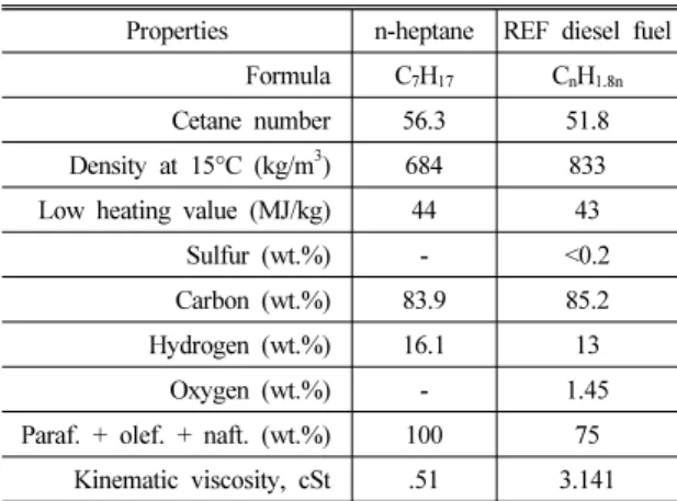
Table 1 Physical properties of n-heptane comparing with reference diesel fuel
Properties n-heptane REF diesel fuel Formula C7H17 CnH1.8n
Cetane number 56.3 51.8 Density at 15°C (kg/m3) 684 833 Low heating value (MJ/kg) 44 43
Sulfur (wt.%) - <0.2 Carbon (wt.%) 83.9 85.2 Hydrogen (wt.%) 16.1 13
Oxygen (wt.%) - 1.45
Paraf. + olef. + naft. (wt.%) 100 75 Kinematic viscosity, cSt .51 3.141
fuel temperature effect on spray penetration is simulated to understand and define the global definition of vapor penetration, liquid penetration and droplet mass for the corresponding parameters.
2. Theory
The Kelvin-Helmholtz (KH) model is based on linear stability analysis of a liquid jet [11] and is used to model the jet’s primary breakup [12] region where the growth rate and wave length of the fastest growing mode was found numerically [12] to be:
∙
∙
Where, = wavelength of the fastest growing wave; = its growth rate; rp = Jet radius; = surface tension and = dimensionless weber number.
Beyond the Breakup Length from the nozzle exit, the Rayleigh-Taylor (RT) model is used together with the KH model to predict secondary breakup of spray droplets [13, 14]. The "breakup length" is predicted by Levich' theory [11] as:
Distance constant in ANSYS FORTE
3. Numerical Method
3.1 Fuel Chemistry
The simulation was performed using the commercial CFD package ANSYS FORTE which is coupled with
a CHEMKIN-PRO solver technology. N-heptane was used as a fuel which chemical kinetics mechanisms and thermodynamic parameters were used from Lawrence Livermore National Laboratory (LLNL) A short mech- anism [15] of 159 species was used in this simulation and its physical properties are compared in Table 1.
By using the physical property on n-tetradecane with the combination of the chemical model of n-heptane to understand the actual diesel spray effect in the chamber.
3.2 Model setup
The present model employed a similar dimension of the experimental constant volume combustion chamber to simulate diesel spray. The computational domain was a constant volume cylindrical chamber with a diameter and length of 108 mm and 28.6 mm, as shown in Fig. 1. The primary mesh was relatively coarse, and the mesh was refined in the spray region through the mesh refinement algorithm in ANSYS FORTE. Also, the mesh sized of 1-3 mm was applied to investigate the mesh dependency.
Fig. 1 Isometric view of disk type CVCC and solid cone injector (–XZ plane) in Computational Domain
Table 2 Simulation case setup & conditions Fuel Type n-heptane (Chemical Species)
n-tetradecane (Physical Properties) Spray Condition Non-vapoizing Vapoizing Injection Pressure 137 MPa 150 MPa
Fuel temperature 451 K
Injection Duration 3 ms 2 ms
Nozzle Diameter 257 µm 80 µm
Chamber Condition
Ambient Density, ρa
14.8, 30.2, 60.6,
124 kg/m3 22 kg/m3 Ambient
Temp., Ta 451 K 800K, 900K and 1000K Varying Fuel
Temperature, Tf 273 K, 283 K and 313 K
Pa= 3.2 MPa; Ta= 626 K;
Pinj = 42.6 MPa
Fig. 2 Experimental schlieren image where the comparison of vapor penetration and liquid penetration is defined through different color contour [17]
3.3 Simulation Condition
In this simulation study, pure n-heptane is sprayed in the computational domain using a solid type cone injector which was located in the middle of the chamber directed toward the opposite wall. Ambient gas density is maintained similar to the vaporizing and non-vaporizing experimental environment by a gaseous blend of nitrogen (N2), water vapor (H2O) and carbon dioxide (CO2) to fulfill the non-reacting experimental spray condition. For fuel injection, a time-based square type injection profile was used.
K-epsilon (k-ε) turbulence model is being implemented with KH-RT breakup model while the collision effect
was not taken into consideration during the simulation.
4. Simulation results & discussion
For the spray visualization and measurement in CVCC, spray penetration is divided into two primary categories termed as vapor phase penetration and liquid phase penetration. Vapor penetration indicates the maximum distance from the nozzle outlet to where the fuel mass fraction (or mixture fraction) is 0.1%
and liquid penetration represents the maximum distance from the nozzle outlet to the farthest axial position for 0.1% liquid volume fraction, averaged over a volume of 1 mm in diameter and 1 mm in axial length [16].
4.1 Effect of ambient gas density
In Fig. 3, the vapor spray penetration at ambient gas density are depicted for the simulation condition mentioned in the graph. Also, the input values used in the numerical calculation are summarized in the non-vaporizing condition in Table 1. Profile of fuel injection rate was acquired by carefully examine the experimental rate profile. At the initial stage, vapor spray penetration of different ambient gas densities are nearly similar and then varied drastically for the corresponding ASOI. From the simulation result it is
Fig. 3 Vapor Penetration Length for increasing ρa
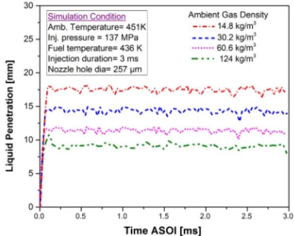
Fig. 4 Liquid Penetration Length for increasing ρa
evident that with the increase of ambient gas density, the vapor tip penetration decreases. This phenomenon can be explained by the anti-shear capability of spray particle. Higher ambient gas density always promotes an anti-shear ability to the spray droplet which resists the spray harder to break during the high load condition of an engine. As it can be observed from Fig. 3, for ASOI 0.15 ms which is very initial stage where evaporation of droplet largely influences the vapor penetration depth. Also, ambient gas density has a considerable effect on vapor penetration length which is unfamiliar at the first stage where the depth is not so wide spreading. On the other hand, in Fig. 4 liquid penetration histories for varying ambient density reveal an initial increment at a certain ASOI which is almost similar and linear and lasts approximately 85 µs.
Then this maximum liquid penetration spreads the liquid length during the quasi-steady period of injection.
Also for increasing ambient gas density, the liquid penetration decreases since fuels evaporate differently
resulting in different liquid penetration rates. This figure also demonstrates that at a fixed injection pressure with increasing ambient density the average droplet mass decreases due to a higher Weber number [18]
which resulting in a lower decreasing trends in liquid penetration length.
To understand the accuracy of this present numerical study, experimental results [3] are plotted and compared with the simulation result for non-vaporizing spray condition. In this simulation, the simulation condition is maintained analogous to the experiment [3]. In Fig. 5, dotted lines represent the simulation result where the symbols indicate the experimental results of Siebers and Naber [3] at the ambient gas density ranging 14.8-124 kg/m3 for maintaining the non-reaction spray condition. From the graph, it can be illustrated that spray tip penetration decreased with the increase of ambient gas density for each momentarily spray dispersion. Analyzing the complete trends throughout the total set of results it can be observed that numerical result validates and predicts well the experimental results of Siebers and Naber [3].
In ANSYS FORTE, fuel spray is simulated by
Fig. 5 Comparison and validation of numerical n-heptane simulation results to experimental results for ambient gas density 14.8-124 kg/m3
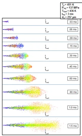
Fig. 6 Spray development, evaporation and dispersion for corresponding 1.5 ms ASOI at ambient density 30 kg/m3
employing Lagrangian particle models, so it is possible to visualize sprays by observing at the Lagrangian particles distributed in the computational domain. In the experiment, the lightness of the spray image has some optical meaning, which is not the same sense of visualizing sprays evaporation and dispersion in the simulation. However, they share some important similarities: in both cases, it can be possible to observe where the spray mass is distributed in the simulation domain. Fig. 6 represents the spray development, evap- oration, and dispersion process for corresponding ASOI.
4.2 Effect of ambient temperature
In this section spray characteristics is further simulated by varying the parameter ambient gas temperature to 800 K, 900 K and 1000 K with a fixed ambient density 22 kg/m3 with an injection pressure and fuel tem- perature 150 MPa and 450K respectively. Moreover, in this section ambient temperature effect will be discussed for vapor penetration, liquid penetration
and droplet mass at the vaporizing spray condition (near 800-1000 K). The similar experiment was carried out by ECN [19] where the injector to opposite wall distance was 109 mm. During the experiment at certain ASOI when the vaporization occurred, vapor phase of penetration for 800 K case reached to the wall at 2600 μs which is equivalent to 2.6 ms for #2 diesel fuel. When the experimental ambient gas temperature was 1000 K, the vapor contour was wide spreading compare to 800K case while the penetration tip did not touch to the opposite wall at same ASOI.
Non-vaporizing spray penetrated more slowly than the vaporizing spray so from the comparison of ex- perimental and simulation result it can be concluded that the vaporizing experimental spray penetration
Fig. 7. Vapor Penetration Length for increasing Ta
Fig. 8. Liquid penetration length for increasing Ta
Fig. 9. Droplet mass for increasing Ta
reaches the wall at 2.6 ms while the simulation result of vaporizing spray penetrates reach the same distance 109 mm at 2.01 ms.
However, from a general overview of the vapor penetration, it can be comprehended that all the curves have a similar trend in this computation study for 800 K, 900 K, and 1000 K case. However, the trend of liquid length and droplet length is almost similar for each of the cases. From the experimentally obtained result of liquid length [16], the liquid spray penetration length for #2 diesel fuel is on average 15 mm ASOI. For the simulation result of fuel temperature
450 K and ambient temperature range 800-1000 K, the result is quite similar and on an average more than 15 mm.
On the other hand, droplet mass for 800, 900 and 1000 K is increasing for higher ambient temperature with a similar trend compare to liquid penetration length. However, at the starting of 0.20 ms, average droplet mass for 900 K and 1000 K is almost similar in compared to 800 K. So the variation is wide spreading with an increase of time.
4.3 Effect of fuel temperature:
Ambient pressure and temperature were maintained 3.2 MPa and 626 K to understand the low-temperature cold starting condition over a wide range of fuel tem- perature 273 K, 283K and 313 K. The injection quantity was 20 mg for each condition. From the simulation result in Fig. 10, it is evident that the vapor phase penetration was increase with the fuel temperature increased. From the experimental result [11] of vapor penetration, it was found that the ASOI at 1.6 ms vapor penetration reached around 29.74 mm, 29.23 mm and 28.86 mm for the fuel temperature of 273 K, 283 K and 313 K respectively. Since their injector
Fig. 10 Vapor Penetration for increasing fuel temperature Fig. 11 Droplet mass for increasing fuel temperature
was a commercial seven hole with a nozzle hole diameter of 0.124 mm while in this numerical study, all the simulation was conducted at 257 µm. As the jet penetration decreases with decreasing orifice diameter [17] so the simulation result of corresponding vapor penetrations are 74.34 mm, 74. 11 mm and 73. 89 mm respectively at 1.75 ms ASOI. So from the dif- ferent start of injection by the agreement of nozzle hole diameter factor for tip penetration it is clear that the increasing range of penetration for 273 K, 283 K and 313 K is near similar while the penetration length is not same at same ASOI due to different nozzle dia.
However, the global effect of the fuel temperature trend is almost similar for both experimental and simulation condition. The reason behind the increased vapor penetration can be illustrated from vaporization of heat energy. Spray needs higher energy for heating up and vaporizing the fuel. As the temperature of fuel decrease, the droplet mass also increase.
On the other hand, the effect of fuel temperature increase is further investigated to overview the droplet mass distribution for corresponding spray dispersion with an increase of time. From the Fig. 11 it is clear that the increase of fuel temperature will lead a
decrease in droplet mass. For the 273 K and 283 K case, the fuel temperature difference is relatively low where the increasing variation of the droplet mass is almost similar for corresponding ASOI ; however when the fuel temperature difference is 40 K, droplet mass distribution for 313 K decreases so rapidly in compare to fuel temperature 283 K and 273 K.
5. Conclusion
Numerical study of diesel spray has been performed by using ANSYS FORTE and unsteady gas jet model to eliminate the mesh size dependency. By comparing the simulation results over experimental result, the following conclusions can be drawn,
1) CFD simulations of vapor spray penetration with KH-RT and unsteady gas jet model is more accurate to predict the experimental spray over a wide range of gas density, ambient temperature and fuel temperature. The standard KIVA-3V spray model of Amsden [20] traditional gas jet profile model predict well the spray tip penetration up to a gas density of about 60 kg/m3. But for higher
ambient density up to 124 kg/m3 and higher ambient temperature 800-1000 K, an unsteady gas jet model of ANSYS FORTE predict far more accurate results.
2) From the simulation results, the vapor and liquid penetration were observed to be directly dependent on the ambient gas density, ambient pressure, ambient temperature and fuel temperature. The previous experiment was conducted to realize the effect of vaporizing vs non-vaporizing, vaporizing vs. combusting diesel spray. However, this vapor- izing simulation result with an ambient temperature 800-1000 K will help to find the accuracy of liquid penetration which is the critical parameter to clear the liquid breakup, dispersion, and mixing. The liquid penetration length is predicted similarly from the experimental result where the droplet mass is calculated to understand the vaporizing condition of traditional diesel spray.
3) Good agreement was found in the simulation result for fuel temperature over from the experimental result. The reason behind the slight difference in vapor spray penetration lends supports to claim from the orifice diameter. Again these results provide confirmatory evidence that due to decrease in fuel temperature resulting weaken spray evaporation process with higher viscosity and density during the cold start condition of a diesel engine.
Acknowledgement
This research was supported by The Leading Human Resource Training Program of Regional Neo industry through the National Research Foundation of Korea (NRF) funded by The Ministry of Science, ICT and Future Planning (2016H1D5A1908826). This research
was also supported by the Industrial Strategic technology development program (10053151, Development of the 800 kPa Fuel System of a High Pressure Precision Control for NGV) funded by the Ministry of Trade, Industry & Energy (MI, Korea).
References
1. D. C. Oren, S. Wahiduzzaman, and C. R. Ferguson,
“A Diesel Combustion Bomb: Proof of Concept”, 1984.
2. H. Hiroyasu and M. Arai, “Structures of Fuel Sprays in Diesel Engines”, 1990.
3. J. D. Naber and D. L. Siebers, “Effects of Gas Density and Vaporization on Penetration and Dispersion of Diesel Sprays”, 1996.
4. T. K. H Hiroyasu, M Arai, “Supplementary comments: fuel spray characterization in diesel engines”, Combustion Modeling in Reciprocating Engines, Plenum Press, New York, pp. 369-405, 1980.
5. J. C. Dent, “A Basis for the Comparison of Various Experimental Methods for Studying Spray Penetration”, 1971.
6. B. V. Rajalingam and P. V. Farrell, “The Effect of Injection Pressure on Air Entrainment into Transient Diesel Sprays”, 1999.
7. J. V. Pastor, R. Payri, J. M. Garcia-Oliver, and F.
J. Briceño, “Schlieren Methodology for the Analysis of Transient Diesel Flame Evolution”, 2013.
8. R. Payri, F. J. Salvador, J. Gimeno, and J. P. Viera,
“Experimental analysis on the influence of nozzle geometry over the dispersion of liquid n-dodecane sprays”, Frontiers in Mechanical Engineering, vol.
1, 2015-October-12 2015.
9. N. A. Henein, A. R. Zahdeh, M. K. Yassine, and W. Bryzik, “Diesel Engine Cold Starting: Combustion Instability”, 1992.
10. J. Hwang, Y. Park, C. Bae, J. Lee, and S. Pyo,
“Fuel temperature influence on spray and combustion
characteristics in a constant volume combustion chamber (CVCC) under simulated engine operating conditions”, Fuel, vol. 160, pp. 424-433, 11/15/
2015.
11. Levich, V. G., Physicochemical Hydrodynamics, Prentice-Hall, New Jersey, ISBN-10: 0136744400, 1962.
12. Reitz, R. D., “Modeling Atomization Processes in High-Pressure Vaporizing Sprays”, Atomization and Sprays, 3: 309-337, 1987.
13. Su, T. F., Patterson, M. A., Reitz, R. D., and Farrell P. V., “Experimental and Numerical Studies of High Pressure Multiple Injection Sprays”, SAE Technical Paper 960861, 1996.
14. Beale, J.C., R.D. Reitz, Modeling spray atomization with the Kelvin–Helmholtz / Rayleigh–Taylor hybrid model. Atomization and Sprays 9, 623-650, 1999.
15. G. B. Joseph Taglialegami, Jr., Eric Osecky and Anthony M. Dean, “Simulation of n-Heptane and Surrogate Fuels for Advanced Combustion Engines (FACE) in a Single-Cylinder Compression Ignition Engine”, 2013.
16. Sanghoon Kook, Lyle M. Pickett, Liquid length
and vapor penetration of conventional, “Fischer– Tropsch, coal-derived, and surrogate fuel sprays at high-temperature and high-pressure ambient conditions”, Fuel, vol. 93, pp. 539-548, ISSN 0016-2361, 2012.
17. Pickett, L.M., Genzale, C.L., Manin, J., Malbec, L.-M., and Hermant, L. “Measurement Uncertainty of Liquid Penetration in Evaporating Diesel Sprays”, ILASS 2011-111.
18. I.V. Roisman, Lucio Araneo, C. Tropea, “Effect of ambient pressure on penetration of a diesel spray”, International Journal of Multiphase Flow, Volume 33, Issue 8, pp. 904-920, ISSN 0301-9322, 2007.
19. L.M. Picket, “Effect of Ambient Gas Temperature, Effect of Nozzle Orifice Diameter in Spray &
Combustion” http://www.sandia.gov/ecn/09tutorials/
tutorial/temperature.php (Retrieved in 2016, August 09).
20. A. A. Amsden, “KIVA-3V: A block-structured KIVA program for engines with vertical or canted valves”, LA-13313- MS, Los Alamos National Laboratory (1997). 1997.
![Fig. 2 Experimental schlieren image where the comparison of vapor penetration and liquid penetration is defined through different color contour [17]](https://thumb-ap.123doks.com/thumbv2/123dokinfo/5109879.574136/4.799.74.385.718.989/experimental-schlieren-comparison-penetration-penetration-defined-different-contour.webp)