Analysis for Torsion of Hollow Beam by Least Squares and Boundary Elements Method
김 치 경† 배 준 태*
Kim, Chi-Kyung Bae, Joon-Tai
···
요 지
본 연구에서는 뒤틀림을 받고 있는 정사각형 단면의 중공단면 보를 최소자승법과 경계요소법을 이용하여 수치 해석하고 구조물을 해석하였다. 임계하중은 하중을 점차적으로 증가하여 구조물이 파괴가 발생하여 안정성을 상실하는 상태에서 가 장 작은 하중을 의미한다. 뒤틀림을 받고 있는 beam은 일반 구조물에서 많이 발생하는 현상이며, 구조물의 안정성에 크게 영향을 미치고 있다. 최소자승법과 경계요소법은 복잡한 구조물에서도 물론, 다양한 경계조건을 포함하는 문제에 이르기까 지 구조물의 안정성을 검사하는데 효과적인 수치해석 방법이다. 특히 뒤틀림의 문제에서는 단순성 및 일반성에 기인하여 매우 적합한 해석방법이다. 본 연구에서는 뒤틀림을 받고 있는 중공단면 보의 해석해를 유도하여 최소자승법으로 수치 해 석하고 또한 경계요소법을 적용하여 빔의 안정성을 비교 검토하였다. 개발한 컴퓨터 프로그램의 타당성을 증명하기 위하여 삼각형, 사각형 그리고 타원형 단면에 대하여 각각 해석하여 해석해와 비교․검토하였다.
핵심용어 : 중공단면 보, 최소자승법, 경계요소법, 비틀림, 해석해
Abstract
In this paper we are concerned with the performance of structural stability of torsion in square cross section of a beam with holes. The critical load is defined as the smallest load at which the equilibrium of the structure fails to be stable as the load is slowly increased from zero. The beams subjected to torsion are frequently encountered in general structures and these forces influence to the stability of structure. The boundary element method is found to be very efficient and accurate for the analysis of torsion problems including complex boundary conditions with respect to its simplicity and generality. In this paper, it is required to derive the boundary element formulation for torsion problem and integrate directly on the discrete boundary. To investigate the validity of the developed computer program, three distinctly solid cross-sections which are elliptical, rectangular and triangular one are analyzed, and comparisons are made with analytical approaches where these can also be used.
Keywords : hollow beam, least squares method, boundary element method, torsion, analytical solution
···
†책임저자, 정회원․인천대학교 안전공학과 교수 Tel: 032-835-8294 ; Fax: 032-835-0779 E-mail: [email protected]
* 인천대학교 안전공학과 석사과정
∙이 논문에 대한 토론을 2012년 6월 30일까지 본 학회에 보내주시 면 2012년 8월호에 그 결과를 게재하겠습니다.
1. Introduction
Torsional forces develop in a member through the direct application of a torque or twisting moment, or they may develop directly because of an off-balanced load or force application. In design, closed forms such as tubes, pipes, or box beams are usually better for carrying torsional forces than are open forms such as
plates or channels. The square hollow beam is frequently used as a deck for curved bridge. However, but the somewhat involved mathematical analysis makes grasping the practical implications of theory difficult for the industrial engineer. In instances where the cross-section considered is not circular which is a noncircular member, the analysis of torsional stresses becomes fairly complex(Chen, et
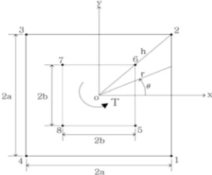
Fig. 1 The domain and dimensions for analysis of a hollow square beam
al., 2000; Sapountzakis, et al., 2004). Solution of non-uniform torsion of bars by an integral equation method). Furthermore, to solve a noncircular cross section torsion problem analytically is, generally speaking, out of the question. Therefore, many attempts, numerical, have been made to describe the stress situation created by the twisting moment. Although many general numerical methods have been and are being used for solving problems in elastic torsion, the currently most popular one probably is the boundary element method. The boundary element method has several potential advantages over the commonly used methods for the solution of boundary value problems (Dumir, et al., 1993; Friedman, et al., 2000; Sapo- untzakis, 2001; 2003; 2007; 2009; Mokos, et al., 2011). Since the Saint-Venant has the torsion of prismatic and cylindrical bars reduced to a mathe- matical calculation of an analytical function satisfying prescribed boundary values, several analytical researches have been achieved in recent years. The analytical theory of torsion due to a twisting moment was first applied by the Saint-Venant(Saint, 1855). Sapoun- tzakis presented a analytical solution for elastic torsion of irregular shapes (Gaspari, et al., 2005).
However, these studies were limited to the linear, a solid and a specific cross section. The only possibility of study in irregularly shaped domains was the beautiful, but limited, theory of complex function analysis and several functional approaches(Sapo- untzakis, 2000; Xu, et al., 2010; Tan, et al., 2011).
These works have shown the tremendous possibilities of the analytical approach which can be solved to the noncircular section member. In most cases, unfor- tunately, the solution is too complicated for a direct practical application. In this paper, it is required to solve the Saint Venant torsion problem analytically for a square cross section beam having a concentric square hole and to discuss the residuals on the boundary. It deals with shear stress distribution at the cross section and torsional rigidity of the cross section. An outline of the analytical method is first presented for torsion problem. The stress function from a torque is analyzed using a appropriate series
procedure. Thus a slightly modified least square program for overdetermined system can be used to calculate the shear stresses of the square beam having a concentric hole(Chou, et al., 1992; Kim, et al., 2009; Zitnan, 2011). Some sample problem which has a solid cross-section are analyzed and discussed.
2. Derivation of Analytical Solution for a Hollow Beam
Analysis of the torsional stress in body of square cross section with a concentric hole leads problem of computing a stress function such that
(1)and the boundary conditions are
on the outside( ±
)
on the inside ( ±
)The beam outside dimension is 2
by 2
and the inside hole dimension is 2
by 2
shown in Fig.1. The outside boundary is bounded by the lines ±
and ±
. The inside boundary is bounded by the lines ±
and ±
. A stress function
is sought such that∇
0 in the interior. A harmonic function
expressed in series form is to be computed such that the boundary conditions are satisfied approximately. The stress function is also to be used to compute the torsional rigidity and the shearstresses distribution in the cross section.
An approximate solution can be formulated in the form of series by using symmetric conditions. By symmetric conditions it follows that an appropriate series form for
is
(2)where n is the number of discrete points. In order to satisfy the boundary conditions approximately the following conditions should be imposed. Let
,
on outside and
on inside. Express the boundary conditions as follows:
(3)
[
]
[
]
on outside boundary and
(4)
]
(
]
on inside boundary. Simplifying the equation by substituting
, the stress function on the outside boundary now becomes
[
(5)
]
for ≤ ≤
and the stress function on inside boundary becomes
[
(6)
]
for ≤ ≤
Quantities to solve for are
,
,
′
and
′
. Taking values
,
,
,
,
,
,
on outside boundary and values
,
,
,
,
,
,
on inside boundary, the equations become as
⋅
⋅
(7)
′
′
,
1,2,3,
,
on the outside boundary and
⋅
⋅
(8)
′
′
,
1,2,3,
,
on the inside boundary. The torsion moment is given by
(9)
[
]
[
[
]
]
[
]Substitution of the boundary conditions,
on the inside boundary
and
on the outside boundary
yields
[
(10)
]where
(11)
]
and
(12)Hence
[
] (13)
[
]The integration of stress function
is given by
(14)
[
[
]
[
]
[
]
[
]
(
)
[
]
]
[
[
]
[
]
[
]Choose a set of values
,
,
,
,
and write an overdetermined system to be solved approximately in the least squares sense for
,
, ′
and
′
,
1,2,3,
,
. This program for solution of coefficients employs Householder transformation and maximum column pivoting strategy to determine the least square solution of a system of equation obtained from boundary. These coefficients can then be used to compute the torsional rigidity and tabulate the shear stresses on a square grid network.3. Boundary Element Formulation
Green's theorem states that for two functions
and
∇ ∇
(15)provided that
and
and their partial derivatives up to the required order are continuous in
and on
. Using the fundamental solution of Laplace's equation in two dimensions Eq.(1) results in the equation
(16)
where
The coefficient
c
is introduced to avoid the singularity of the integrals. To evaluate the domain integral
, Green's second identity keeping∇
and∇
are introduced.
(17)where
. For
is a constant, therefore
(18)Finally, Eq.(16) can be written as
or
(19)where
. To evaluate torsional constant
, apply Green's second identity and choose
and also∇
, the equation becomes
Thus
(20)Eq.(19) contains boundary integrals that are to be solved for prescribed potential functions and stresses.
For arbitrary geometry, this equation is hard to solve, and thus the boundary is discretized into finite segments, called boundary elements. For a two dimensional potential mechanics problem, the boundary
is a line and it can be divided into a discrete number of line elements. In this study, these line elements are assumed to be linear elements with two nodes.
Eq.(19) can be written for the elements as;
(21)
Consider the case of boundary values of
and
on the discrete line element given by an interpolation function such that:
,
(22)where
is the dimensionless coordinate
=2
and are given by
,
The integral along a
element in Eq.(21) becomes for the left hand side,
(23)where
,
To write the equation corresponding to node
in discrete form we need to add the contribution two adjoining elements(
) and
into one term, defining the nodal coefficient. Substituting Eqs.(22) and (23) for all
elements into Eq.(22) one obtains the following equation for node
(24)(a) (b) (c)
Fig. 2 Geometry and discretization of various cross sections.
where
,
is equal to the
term of element
plus
term of element (
) and similarly for
. Hence Eq.(28) represents the assembled equation for nodei
. Eq.(24) can be written as
(25)and the whole set for the nodes in matrix form becomes
(26)On the smooth boundary in two dimensional problems, the value of
is obtained as
. Note that
values of
and
values of
are known, hence one has a set of unknowns in Eq.(24).Reordering the equations in such a way that all the unknowns are on the left hand side, one can write as
(27)where
X
is the vector of unknowns
and
. Once the values of
and
on the whole boundary are known one can calculate the value of
at any interior point as follows :
(28)4. Numerical Implementation
To validate the derived formulation of the analytical solution and its efficiency, the solution of a simple problem is presented. For the purpose of
comparing the numerical results of the present method, cases which involve three distinct solid cross-sections are studied.
Case a) Elliptical cross-section, where
4cm
2cmCase b) Rectangular cross-section, where
4cm
2cmCase c) Equilateral triangular cross-section, where
2cmSince we will verify numerical solutions of this computational model against analytical solutions(Boresi, et al.,1978), we have solved a single variable with
1.0 and
1.0 for simplicity. The analytical solution(maximum stress) for these problems are obtained as
where
is called the torsional rigidity of the section for ellipse,
,
where
is called the torsional rigidity of the section for equilateral triangle and
,
where
0.229,
0.246 and
is called the torsional rigidity of the section for rectangleCross sec. Max. stress Tors. rigidity Ellipse 1.5851 (1.6000) 4.9811 (5.0240) Triangle 1.0191 (1.0000) 0.6263 (0.6158) Rectangle 1.8887 (1.8618) 7.4344 (7.3282) ( ) : Analytical solution
Table 1 Comparison of the calculated solution in various cross-sections.
(a) (b)
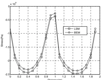
Fig. 3 Geometry and discretization of a hollow beam of square cross section
0 0.2 0.4 0.6 0.8 1 1.2 1.4 1.6 1.8 2
-2.5 -2 -1.5 -1 -0.5
0 x 10
8Distance(m)
St re ss (Pa )
LSM BEM
Fig. 4 Comparison of the stresses on outside boundary of beam using boundary element with the analytical
solution
respectively. For investigation of the effect of gridspacing on the results, runs were made for thirty two elements for elliptical cross-section, forty elements for rectangular cross-section and thirty five elements for triangular cross-section which are uniformly discretized as shown in Fig. 2. Table 1 shows numerical solutions for each of boundary element method compared to the analytical solutions. The results give very close agreement to the analytical solution for the solid cross-section. They are under and over estimated the solution by almost 2% respectively.
We now consider the extensional problem for a hollow concrete bar of rectangular cross section. The domain and boundary conditions are shown in Fig.3a.
The bar is subjected to a angle of twist of 0.05
along its longitudinal axis. For concrete, typical value of is 9.0×10
5
N/m2
. Because of symmetry one needs to consider a quarter of the domain. Fig.3b exhibits the subdivision(=35), characterized by a constant interval on the straight boundary and shows the prescribed
and
values along the boundary.Twisting is induced rigidly into the beam by its framing. The torsional stresses in such a beam are again dependent on the twisting moment, the location of the point considered, and the properties of the cross section.
Stresses on outside boundary in beam of a hollow beam of rectangular cross-section are presented in Fig. 4. The boundary element solution gives close agreement to the analytical solution. They under and over estimated the solution by almost 2% respectively.
Twisting is induced rigidly into the beam by its framing. The torsional stresses in such a beam are dependent on the twisting moment, the location of the point considered, and the properties of the cross section.
5. Conclusions
In this paper, torsion with a square cross section beam having a concentric square hole was analyzed using an appropriate series procedure(least squares method) and boundary element method. To validate the derived formulation of the analytical solution (least squares method), computer program for a torsional problem has been developed for the least square method. One sample problem which involves a squarely solid cross section was discussed and illustrated, and comparisons with analytical solutions where these can also be used were made. The results of boundary element method show that the solutions are in good agreement with the analytical results.
Furthermore, the most interesting result of the theory is the derivation of a single formula capable of
predicting the moment and stress with fairly good accuracy for ranges of stress. As result of the direction of the torque, the distribution of stress produced at the middle of the outside boundary tends to become constant. As illustrated through sample examples, this analytical approach and boundary element method were found to be very efficient and accurate for analysis of torsion problem with a hollow square cross section and that they afford a close analysis of the noncircular cross section in torsion.
Reference
Boresi, A.,Sidebottom, O., Seely, F. B., Smith, J.O. (1978) Advanced Mechainics of Materials, John Wiley and Sons, New York, pp.210~252.
Chen, J.T., Chen, Y.W. (2000) Dual Boundary Element Analysis using Complex Variables for Potential Problems with or Without Degenerate Boundary, Engineering Analysis with Boundary Elements, 24, pp.671~684.
Chou, S.I., Shamas-Ahmadi, M. (1992) Complex Variable Boundary Element Method for Torsion of Hollow Shafts, Nuclear Engineering and Design, 136, pp.255~263.
Dorao, C.A., Tackbsen, H.A. (2007) Least-squares Spectral Method for Solving Advective Population Balance Problems, Journal of Computational and Applied Mathematics, 201, pp.247~257.
Dumir, P.C., Kumar, R. (1993) Complex Variable Boundary Element Method for Torsion of Anisotropic Bars, Applied Mathematical Modelling, 17, pp.80~
88.
Friedman, Z., Kosmatka, J.B. (2000) Torsion and Flexure of a Prismatic Isotropic Beam using the Boundary Element Method, Computers & Structures, 74, pp.479~494.
Gaspari, D., Aristodemo, M. (2005) Torsion and Flexure of Orthotropic Beams by a Boundary Element Model, Engineering Analysis with Boundary Elements, 29, pp.850~858.
Kim, S.D., Shin, B.C. (2009) Adjoint Pseudospectral Least-Squares Methods for an Elliptic Boundary Value Problems, Applied Numerical Mathematics, 59, pp.334~348.
Mokos, V.G., Sapountzakis, E.J. (2011) Secondary
Torsional Moment Deformation Effect by BEM, International Journal of Mechanical Sciences, 53, pp.897~909.
Sapountzakis, E.J., Mokos, V.G. (2007) 3-D Beam Element of Composite Cross Section Including Warping and Shear Deformation Effect, Computers
& Structures, 85, pp.102~116.
Sapountzakis, E.J. (2001) Nonuniform Torsion of Multi-Material Composite Bars by the Boundary Element Method, Computers & Structures, 79, pp.2805~2816.
Sapountzakis, E.J., Mokos, V.G. (2003) Warping Stresses in Nonuniform Torsion of Composite Bars by BEM, Computer Methods in Applied Mechanics and Engineering, 192, pp.4337~4353.
Sapountzakis, E.J. (2000) Solution of Non-Uniform Torsion of Bars by an Integral Equation Method, Computers & Structures, 77, pp.659~667.
Sapountzakis, E.J., Mokos, V.G. (2004) Non- uniform Torsion of Composite Bars of Variable Thickness by BEM, International Journal of Solids and Structures, Vol. 41, pp.1753~1771.
Sapountzakis, E.J., Tsipiras, V.J. (2009) Non- linear Inelastic Uniform Torsion of Composite Bars by BEM, Computers & Structures, 87, pp.151~
166.
Saint Venant, B. (1885) De la Torsion des Prismes, Imprimerie periale. Paris
Tan, E.L., Uy, B. (2011) Nonlinear Analysis of Composite Beams Subjected to Combined Flexure and Torsion, Journal of Constructional Steel Research, 67, pp.790~799.
Xu Rongqiao, He Jiansheng, Chen Weiqui.
(2010) Saint-Venant Torsion of Orthotropic Bars with Inhomogeneous Rectangular Cross Section, Composite Structures, 92, pp.1449~1457.
Zitnan, P. (2011) Discrete Weighted Least-Squares Method for the Poisson and Biharmonic Problems on Domain Smooth Boundary, Applied Mathematics and Computation, 217, pp.8973~8982.