• 검색 결과가 없습니다.

A study on the design of nozzle propeller for trawler

N/A
N/A
Protected

Academic year: 2021

Share "A study on the design of nozzle propeller for trawler"

Copied!
11
0
0

로드 중.... (전체 텍스트 보기)

전체 글

(1)

. J. Kor. Soc. Fish. Tech., 44(3), 239 249, 2008

DOI:10.3796/KSFT.2008.44.3.239

A study on the design of nozzle propeller for trawler

Seong-Jae J EONG *, Jin-Keun H ONG

1

, Jong-Deok C HOI

1

and Su-Ho K IM

1

Fisheries Engineering Division, National Fisheries Research & Development Institute, Busan, 619-705, Korea

1

Dongwon Industries Co., Ltd., Wonyang Plaza 3rd Fl., Amnam-Dong 620-29, Seo-Gu, Busan, 602-833, Korea

Trawlers have to a sufficient towing force due to it s characteristics of the high performance. The newly constructed trawler with the conventional propellers shows the sufficient towing force, so that the propeller and engine are optimized. In the 1970s, many trawlers were imported from overseas by Korean fisheries industries. But the engine output degradation with year by year caused the trawlers to decrease the towing speed of the vessels. On the previous studies, the nozzle propeller had not so good efficiency with increasing of resistance in high-speed cruising operation over 15knots. But the trawling operation is just required the higher thrust and towing force, so that the nozzle propeller is very profitable for the it s effectiveness. A new nozzle propeller was designed for the 4,462G/T trawler, Dong-San, operated by Dongwon Industries Co., Ltd. to improve the towing speed, and the model tests were performed. The model ship and model propeller are preciously manufactured and used model tests in basin. The resistance test and propeller open water test were performed for the cases of the half and full loads. The required engine horse power and RPM were evaluated analytically by the speed-power curve, when the trawler was equipped with the nozzle propeller.

The results of tests showed that the towing speed 4.85knots on the design load waterline requires the 200 engine RPM and 2,567ps in the delivered horsepower.

Key words : Trawler, Ducted propeller(Kort nozzle propeller), Design

* Corresponding author: denkmal@nfrdi.go.kr, Tel: 82-51-720-2592, Fax: 82-51-720-2586

(2)

.

.

. 70

.

.

(Ducted propeller or Kort nozzle propeller) 1934 Kort

(Kort, 1934) , 50 60

(Manen and Oosterveld, 1966, Wessinger and Maass, 1968).

NSMB (Netherlands Ship Model Basin) (Oosterveld, 1973).

(tugs), (push boats), (supply vessels)

(Lewis, 1988).

.

15knots

,

(Carlton, 1994).

( ) 4,462G/T

.

, ,

.

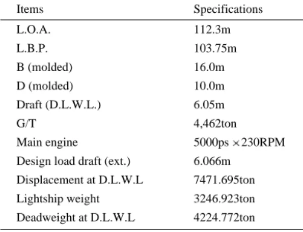
(L.B.P) 103.75m, (B) 16m, (D) 10m,

4,462G/T 5,000ps

. (L.O.A) 112.3m , (draft) 6.05m .

Table 1 .

. ( )

FRP 1:40 .

1/100 5

.

Table 1. Principal dimensions of trawler Dong-San

Items Specifications

L.O.A. 112.3m

L.B.P. 103.75m

B (molded) 16.0m

D (molded) 10.0m

Draft (D.L.W.L.) 6.05m

G/T 4,462ton

Main engine 5000ps 230RPM

Design load draft (ext.) 6.066m

Displacement at D.L.W.L 7471.695ton

Lightship weight 3246.923ton

Deadweight at D.L.W.L 4224.772ton

(3)

Fig. 1 .

(ITTC) Reynolds Number (3.0E 5 )

170mm (KRIS, 1980).

1:16 .

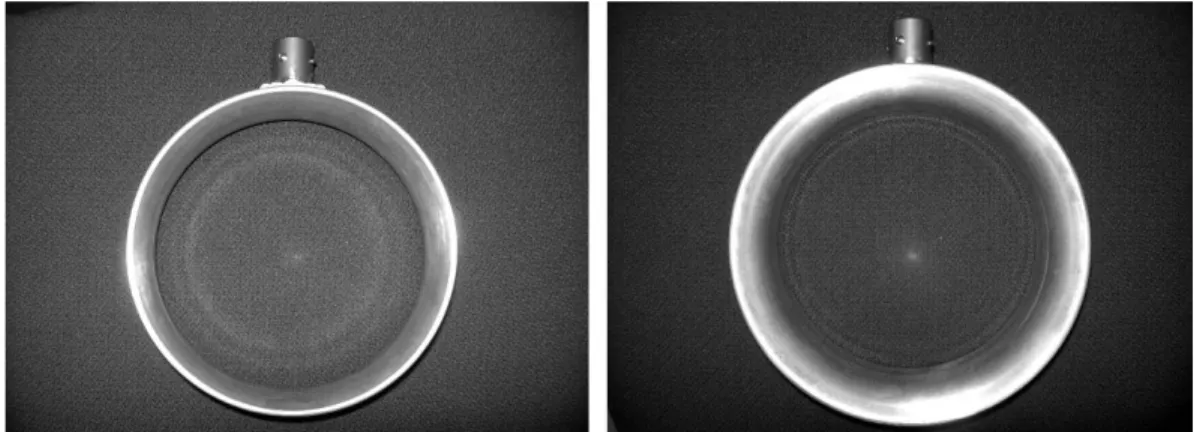
Fig. 2 Fig. 3 .

Fig. 1. Photographs of the model ship.

Fig. 2. Photographs of the model propeller (face:left, back:right).

Fig. 3. Photographs of the model nozzle (face:left, back:right).

(4)

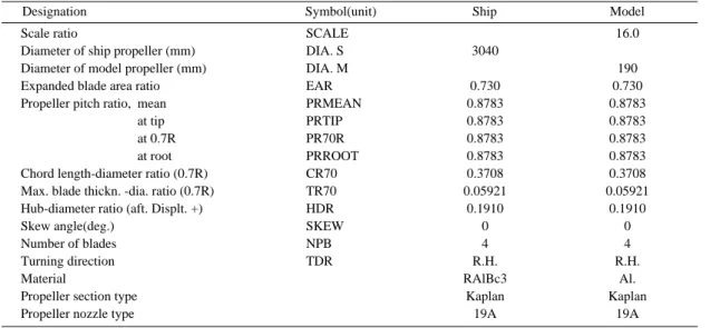
Table 2

Table 3 . Nozzle section

Kaplan Marine Nozzle No.

19A Section (Lewis,

1988).

,

. Table 2. Load conditions by model tests

Designation Scale ratio Load condition Draft, moulded

Length between per.

Breadth, moulded depth, moulded Number of propeller Length of waterline Wetted surface area Displacement volume KB above moulded BL LCB from midship, f+

LCF from midship, f+

Block coef.

Load waterline coef.

Midship section coef.

Prismatic coef.

LPP/B LPP/T B/T

Symbol(unit) Full load Half load

SCALE

TF(m) TA(m) TMEAN(m) LPP(m) B(m) D(m) NOPROP LWL(m) S(m

2

) DISV(m

3

) KB(m) LCB(m) LCF(m) CB CW CM CP

Full load 6.05 6.05 6.05 103.75

16.0 10.0 1 108.15

2307.

7448.

3.207 0.715 3.307 0.722 0.856 0.994 0.727 6.484 17.148

2.644

Fishing condition 4.05 5.82 4.939 103.75

16.0 10.0 1 106.15

2024 5739 2.60 0.296 1.152 0.699 0.796 0.992 0.704 6.484 21.006

3.239

Table 3. Principal dimensions of model propeller

Designation Scale ratio

Diameter of ship propeller (mm) Diameter of model propeller (mm) Expanded blade area ratio Propeller pitch ratio, mean

at tip at 0.7R at root Chord length-diameter ratio (0.7R) Max. blade thickn. -dia. ratio (0.7R) Hub-diameter ratio (aft. Displt. +) Skew angle(deg.)

Number of blades Turning direction Material

Propeller section type Propeller nozzle type

Symbol(unit) Ship Model

SCALE DIA. S DIA. M EAR PRMEAN PRTIP PR70R PRROOT CR70 TR70 HDR SKEW NPB TDR

3040

0.730 0.8783 0.8783 0.8783 0.8783 0.3708 0.05921

0.1910 0 4 R.H.

RAlBc3 Kaplan 19A

16.0

190 0.730 0.8783 0.8783 0.8783 0.8783 0.3708 0.05921

0.1910 0 4 R.H.

Al.

Kaplan

19A

(5)

85m, 10m, 3.5m

. Froude

, ITTC 1978

performance prediction method 2 .

(resistance test) (propeller open-water test: POW)

.

(full load) (half load) ,

3 6knots , 8

16knots

. Full load Half

load condition 12knots

Fig. 4 .

J

A

V

A

/nD(V

A

, n

, D ) ,

n 13 RPS (round per second) .

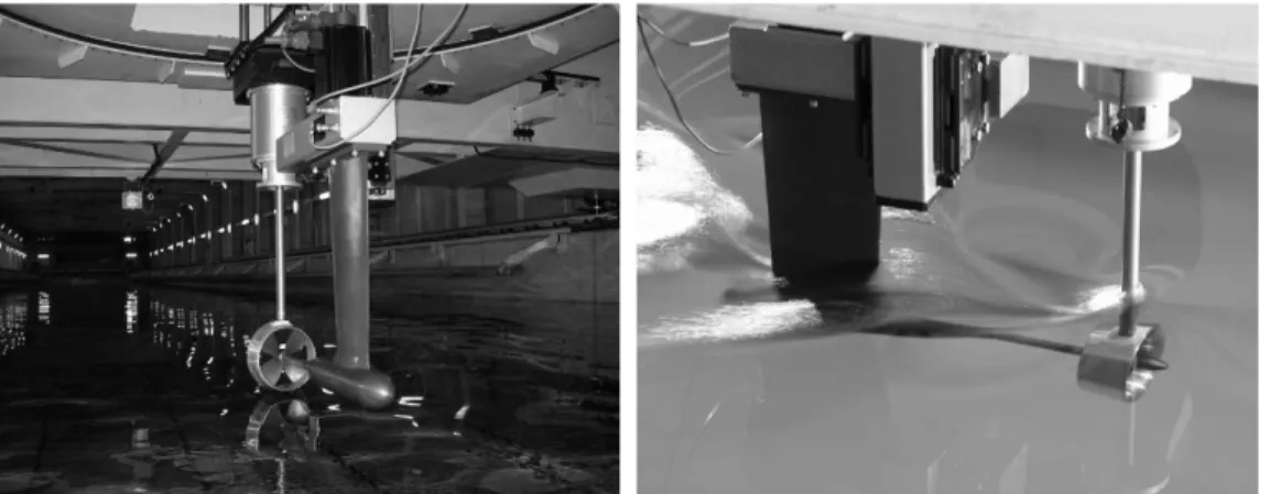
Fig. 5 . Propeller Nozzle

. MARINE Nozzle

section No. 19A NSMB(Netherlands Ship Model Basin)

Fig. 4. Experimental scene with 12[kts] speed under full (left) and half load (right) condition.

Fig. 5. Experimental scene by propeller open water (POW) tests.

(6)

P/D 0.8783 Fig. 6 Fig. 7

. NSMB P/D

P/D 0.8 1.0 P/D 0.8783

.

J

A

0.25

0.45

.

,

.

NSMB 0.25

0.45 ,

.

.

Full load Half load con- dition

Table 4 Table 5

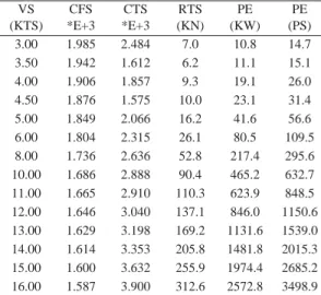
. VS , CFS

, CTS , RTS

, PE

KW PS .

Full load condition 4.5knots 10kilo newton ,

31.4ps Fig. 6. Comparison of K

T

values from the tests of

MARINE 19A and NFRDI at P/D 0.8783.

0.55 0.5 0.45 0.4 0.35 0.3 0.25 0.2 0.15 0.1

0.05 0 0.1 0.2 0.3 0.4 0.5 0.6 0.7

J

A

K

T

Fig. 7. Comparison of K

Tn

values from the tests of MARINE 19A and NFRDI at P/D 0.8783.

0.3 0.25 0.2 0.15 0.1 0.05 0 -0.05

0 0.1 0.2 0.3 0.4 0.5 0.6 0.7

J

A

K

Tn

Table 4. Resistance performance (full load condition) VS

(KTS) CFS

*E+3 CTS

*E+3 RTS (KN)

PE (KW)

PE (PS) 3.00

3.50 4.00 4.50 5.00 6.00 8.00 10.00 11.00 12.00 13.00 14.00 15.00 16.00

1.985 1.942 1.906 1.876 1.849 1.804 1.736 1.686 1.665 1.646 1.629 1.614 1.600 1.587

2.484 1.612 1.857 1.575 2.066 2.315 2.636 2.888 2.910 3.040 3.198 3.353 3.632 3.900

7.0 6.2 9.3 10.0 16.2 26.1 52.8 90.4 110.3 137.1 169.2 205.8 255.9 312.6

10.8 11.1 19.1 23.1 41.6 80.5 217.4 465.2 623.9 846.0 1131.6 1481.8 1974.4 2572.8

14.7

15.1

26.0

31.4

56.6

109.5

295.6

632.7

848.5

1150.6

1539.0

2015.3

2685.2

3498.9

(7)

. 13knots 1,539ps

. Half load condition

, 13knots

149.6kilo newton ,

1360.7ps .

13knots , (full load) (half

load) 178.3ps

.

. J

A

0.35

15% Sea margin

.

, .

. K

Tn

.

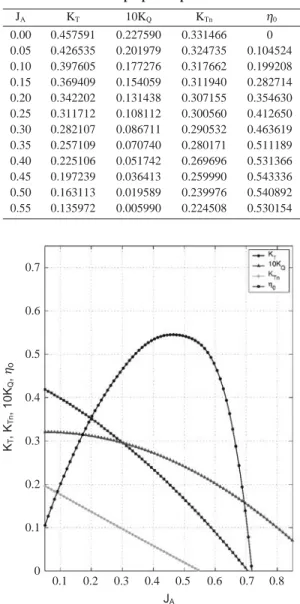
Table 6 Fig. 8 .

J

A

, K

T

,

10K

Q

10 , K

Tn

, η

0

. J

A

0.35

, 13RPS

K

T

0.2571, Fig. 8. Open-water characteristics of the model propeller.

Table 6. Test results of propeller open-water model test

0.7

0.6

0.5

0.4

0.3

0.2

0.1

0 0.1 0.2 0.3 0.4 0.5 0.6 0.7 0.8 J

A

K

T

, K

Tn

, 10K

Q

, η

o

J

A

K

T

10K

Q

K

Tn

η

0

0.457591 0.426535 0.397605 0.369409 0.342202 0.311712 0.282107 0.257109 0.225106 0.197239 0.163113 0.135972

0.227590 0.201979 0.177276 0.154059 0.131438 0.108112 0.086711 0.070740 0.051742 0.036413 0.019589 0.005990

0.331466 0.324735 0.317662 0.311940 0.307155 0.300560 0.290532 0.280171 0.269696 0.259990 0.239976 0.224508

0 0.104524 0.199208 0.282714 0.354630 0.412650 0.463619 0.511189 0.531366 0.543336 0.540892 0.530154 0.00

0.05 0.10 0.15 0.20 0.25 0.30 0.35 0.40 0.45 0.50 0.55 Table 5. Resistance performance (half load condition)

VS (KTS)

CFS

*E+3 CTS

*E+3 RTS (KN)

PE (KW)

PE (PS) 9.00

10.00 11.00 12.00 13.00 14.00 15.00 16.00

1.709 1.686 1.665 1.646 1.629 1.614 1.600 1.587

3.232 3.114 3.222 3.033 3.223 3.353 3.546 3.701

71.9 85.5 107.1 120.0 149.6 180.6 219.1 260.3

333.0 440.0 606.0 740.5 1000.5 1300.3 1690.9 2142.4

452.8

598.4

824.2

1007.1

1360.7

1768.4

2299.6

2913.6

(8)

K

Q

0.00707, K

Tn

0.2802 η

0

0.5112

.

, Table 7

. Tension

,

EHP . Table 4

RT

, Table 7 .

Table 7 5.0knots

26,506.7kgf , 909ps .

56.6ps 965.6ps 5.0knots

, .

Sea margin(S/M)

Table 8 .

.

η

ed

0.90

, η

T

0.97 .

(bare hull) 8%

.

Table 8 EHP

. 3 7knots (W)

(T) 0.292 0.204

.

RPM ( : ETA0, :

ETAH, : ETAR, : ETAD)

ITTC 1978 method DHP

Table 8 .

Table 7. Resistance characteristic of net by trawling condition

Trawler speed(kts) Total tension(kgf)

EHP(ps) RT(ps)

3.0 3.5 4.0 4.5 5.0 6.0

11378.4 234.0

14.7

14400.6 345.7

15.1

17645.9 484.1

26.0

21830.5 673.8

31.4

26506.7 909.0

56.6

38462.0 1582.8

109.5

Table 8. Speed-power prediction (trawling condition w/o S/M)

VS (KTS) 3.00 3.50 4.00 4.50 5.00 5.50 6.00 6.50 7.00

EHP (PS) 1 W

1 T KT/J2 JTS RPM ETA0 ETAH ETAR ETAD DHP

261.2 .708 .796 13.8155

.1613 133.68

.297 1.124 1.020 .3404 767.3

378.8 .708 .796 12.6172

.1678 149.90

.306 1.124 1.020 .3508 1079.9

535.6 .708 .796 11.9514

.1719 167.24

.312 1.124 1.020 .3575 1498.0

740.4 .708 .796 11.6034

.1742 185.68

.315 1.124 1.020 .3614 2048.8

1013.9 .708 .796 11.5835

.1743 206.16

.315 1.124 1.020 .3616 2803.9

1349.6 .708 .796 11.5844

.1743 226.78

.315 1.124 1.020 .3616 3732.3

1776.9 .708 .796 11.7480

.1733 248.95

.314 1.124 1.020 .3598 4939.2

2218.3 .708 .796 11.5355

.1747 267.51

.316 1.124 1.020 .3622 6125.2

2813.9 .708 .796 11.7158

.1745 290.09

.314

1.124

1.020

.3601

7813.9

(9)

RPM Trawling condition Sea margin , Service condition

15% Sea margin .

Fig. 9 RPM 200

, 4.85knots

2,567ps .

RPM 230

5.59knots ,

3,963ps .

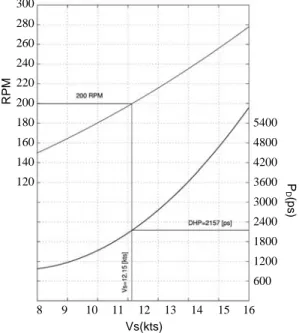
Full load

Fig. 10 . RPM 200

11.75knots 2,156ps

. Half load RPM 200

2,157ps , 12.15knots

Fig. 11 .

,

.

Fig. 9. Prediction of powering performance (trawling , condition w/o S/M).

Fig. 10. Prediction of powering performance (full load w/

15% S/M).

300 280 260 240 220 200 180 160 140 120

300 280 260 240 220 200 180 160 140 120

3 3.5 4 4.5 5 5.5 6 6.5 7

8 9 10 11 12 13 14 15 16

RPM RPM

Vs(kts)

Vs(kts)

P

D

(ps) P

D

(ps) 5400 4800 4200 3600 3000 2400 1800 1200 600

5400 4800 4200 3600 3000 2400 1800 1200 600

Fig. 11. Prediction of powering performance (half load w/

15% S/M).

300 280 260 240 220 200 180 160 140 120

8 9 10 11 12 13 14 15 16

RPM

Vs(kts)

P

D

(ps)

5400

4800

4200

3600

3000

2400

1800

1200

600

(10)

.

100%

.

(power

margin) .

(engine margin) (normal

continuous rating: NCR)

(maximum continuous rating: MCR) 75 90% (Park and Kim, 1988).

RPM (Service condition) ,

Table 9 .

,

.

, .

.

.

.

, 230RPM

5.59knots , 200RPM 4.85knots .

230RPM 5.172knots 200RPM

4.5knots . 230RPM

0.418knots 7.5%

, 200RPM 7.2%

.

, Rack position

.

,

12.5knots .

Table 9. Engine margin by trawling and service conditions Condition

Trawling (full load) (w/o S/M)

Service (half load) (w/ 15% S/M)

Service (full load) (w/ 15% S/M)

RPM(N) Speed(kts) Required

power(ps)

Available power(ps)

Engine margin(%) 190

200 230 190 200 230 190 200 230

4.59 4.85 5.59 11.58 12.15 13.73 11.58 12.15 13.73

2159 2567 3963 1820 2157 3383 1820 2157 3383

2734 3189 4850 2734 3189 4850 2734 3189 4850

21.0%

19.5%

18.3%

33.4 %

32.3 %

30.2 %

33.4 %

32.3 %

30.2 %

(11)

,

.

( )

(2007. 6) ,

( )

( ) .

Carlton, J.S., 1994. Marine Propellers and Propulsion.

Butterworth Heinemann, pp. 15 17.

Kort, L., 1934 Der neue Duesenschrauben Antrieb.

Werft-Reederei-Hafen, Jahrgang 15. Heft 4, pp.

41 43.

KRIS(Korea Research Institute of Ships), 1980. A Study on the development of self propulsion test in model basin. Report of KRIS, pp. 17 19.

Lewis, Edward V., 1988. Principles of naval architecture second revision. Vol. II Resistance, Propulsion and Vibration, pp. 213 225.

Manen, J.D., and M.W.C. Oosterveld, 1966. Analysis of ducted propeller design. Transactions of the Society of Naval Architects and Marine Engineers, 74, 522 562.

Oosterveld, M.W.C., 1973. Ducted propeller characteristics, Paper No. 4., Proceedings RINA Symposium on Ducted Propellers, Teddington, England, pp. 35 68.

Park, M.K. and Y.J. Kim, 1988. On the margin conception and design point in ship s propeller design. Journal of Korea Society of Marine Engineering, 12, 141 152.

Weissinger, J. and D. Maass, 1968. Theory of the ducted propeller, A review. 7th Symposium on Naval Hydrodynamics, ONR, pp. 1209 1264.

2008 7 22

2008 7 29 1

2008 8 4

수치

Table 1. Principal dimensions of trawler Dong-San
Fig. 3. Photographs of the model nozzle (face:left, back:right).
Table 3 . Nozzle section
Fig. 5 .  Propeller Nozzle
+6

참조

관련 문서

The index is calculated with the latest 5-year auction data of 400 selected Classic, Modern, and Contemporary Chinese painting artists from major auction houses..

The key issue is whether HTS can be defined as the 6th generation of violent extremism. That is, whether it will first safely settle as a locally embedded group

1 John Owen, Justification by Faith Alone, in The Works of John Owen, ed. John Bolt, trans. Scott Clark, "Do This and Live: Christ's Active Obedience as the

Five days later, on 15 January 1975, the Portuguese government signed an agreement with the MPLA, FNLA and UNITA providing for Angola to receive its independence on 11

Usefulness of co-treatment with immunomodulators in patients with inflammatory bowel disease treated with scheduled infliximab maintenance therapy.. Oussalah A, Chevaux JB, Fay

Inclusion and Inclusiveness: Shared Vision of Youth for Local, National, and Global Village Inclusion at large stands for embracing populations with disabilities and

웹 표준을 지원하는 플랫폼에서 큰 수정없이 실행 가능함 패키징을 통해 다양한 기기를 위한 앱을 작성할 수 있음 네이티브 앱과

It is impossible to change the voltage across a capacitor by a finite amount in zero time, for this requires an infinite current through the capacitor.. (A capacitor resists