pISSN 1229-3008 eISSN 2287-6251
Progress in Superconductivity and Cryogenics
Vol.17, No.3, (2015), pp.62~66 http://dx.doi.org/10.9714/psac.2015.17.3.062
```
1. INTRODUCTION
The program named rare isotope science project (RISP) to develop the heavy ion accelerator facility as one of the new innovative and challenging tools for basic and applied sciences was initiated by the Institute for Basic Science (IBS). The conceptual design of the facility has completed [1] and the schematic layout of the heavy ion accelerator complex is shown in Fig. 1 [2]. The Korea Basic Science Institute (KBSI), as a research partner, has been involving this program to develop a cryostat for the quadrupole triplet magnet in the in-flight fragmentation (IF) separator.
The main cryostat should be designed to hold the heavy cold mass including iron yoke using an efficient cooling method.
Two types of the cryogenic system are considered for the IF separator quadrupole magnets. One is the dewar type which requires periodic liquid helium transfer from an external storage to operate the magnets for a long time. The other is the cryocooler type which is an attractive way for cooling of superconducting magnets because no refilling of cryogenic liquid is required. However, several ancillary requirements such as background field, space restriction due to the beam line and mechanical structure need technical attentions. The purpose of the work is the development of cryogenic cooling system for the superconducting quadrupole magnet including feasibility study of our design for the IF separator.
The liquid helium plant and external storage are not ready in the IBS site, therefore the cryocooler type is considered to be fabricated for performance test including field mapping without relying on liquid helium supply. In this paper, the status of the development of cryocooler type cryostat for quadrupole triplet magnet is presented. The design of the main cryostat is carried out based upon the associated analysis and the concept of the cryocooler type cooling system is described. The binary current lead is optimized to reduce heat leakage and the design of support
Design of cryostat for superconducting quadrupole magnets in In-Flight fragmentation separator
Y. S. Choi*,a, H. M. Changb, B. Baudouyc, D. G. Kimd and J. W. Kimd
a Korea Basic Science Institute, Daejeon, Korea
b Hong Ik University, Seoul, Korea
c CEA Saclay, France
d Institute for Basic Science, Daejeon, Korea
(Received 17 August 2015; revised or reviewed 16 September 2015; accepted 17 September 2015)
Abstract
The cryostat is designed for the superconducting quadrupole magnets to be used in a heavy-ion accelerator facility. The main accelerator is superconducting linac, which can accelerate a 238U beam to 200 MeV/u (Mega electron voltage per nucleon). The cryostat for the magnet employs an innovative design primarily driven by the requirement of the compactness, user-friendliness and reliability. Also, several ancillary requirements such as background field, space restriction due to the beam line and cryostat structure need technical attentions. The development of the cryostat for three quadrupole magnets in the in-flight fragmentation separator is presented in the paper. The concept of cryogenic design is reported and the amount of cryogenic load is estimated by a relevant analysis. The structure of the cryostat to endure the heavy iron yoke including three quadrupole magnets is presented. In addition, the design as well as the performance test of the support link for the cold mass is described.
Keywords: Accelerator, Cryostat, Heat load, Superconducting magnets
* Corresponding author: [email protected]
Fig. 1. Schematic layout of heavy ion accelerator facility from [2]. (ECR-IS: Electron Cyclotron Resonance-Ion Sources, RFQ: Radio Frequency Quadrupole, MEBT:
Medium Energy Beam Transport, SCL: Superconducting Linear accelerator, CB: Charge Breeder)
Y. S. Choi, H. M. Chang, B. Baudouy, D. G. Kim, and J. W. Kim
to endure the heavy cold mass including iron yoke is discussed. In addition, the performance test of the support link is presented.
2. LTS QUADRUPOLE MAGNET DESIGN 2.1. LTS Quadrupole Magnet
The in-flight fragment separator is designed to have a momentum acceptance of ± 3% and an angular acceptance of ± 50 mrad with a maximum magnetic rigidity of 9.6 Tm.
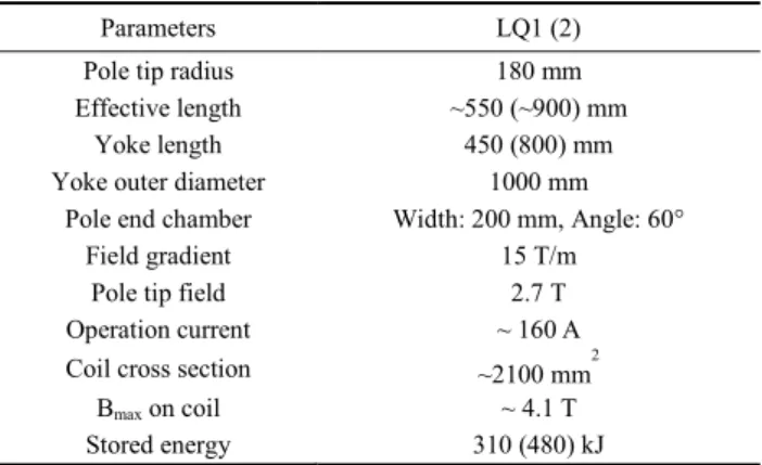
The LTS quadrupole magnet consists of two shorter magnets (LQ1) and one longer center magnet (LQ2). The required field gradient and half aperture of quadrupole magnet are 15 T/m and 12 cm, respectively. Main parameters of LTS quadrupole magnet are listed in Table I.
2.2. Quadrupole Magnet Design
The pole shape of quadrupole magnet together with coil position is adjusted to reduce the higher harmonics of magnetic field in the operation range up to 15 T/m. Fig. 2 shows a quadrant cross section of LTS magnet. The LTS quadrupole coil is designed as a racetrack type having a pentagonal cross section for large operation current margin.
The maximum operating current is about 160 A, and the ratio of operating current to the critical current of wire is
about 35%. The pole ends are chamfered to reduce the higher harmonics in the low field gradient region.
3. QUADRUPOLE MAGNET CRYOSTAT 3.1. Cryogenic Load
Fig. 3 shows the conceptual view of cryocooler type cryostat including the cold iron yoke and the main parameters of the cooling system are summarized in Table II. In a cryostat, superconducting coils are located in the middle of the iron yoke and suspended by gravitational and transversal supports. The liquid helium vessel is designed to be suspended from the outer vacuum vessel with axial suspension system. The suspension type is employed for gravitational support, having an intercept connected to the thermal shield. Two stage cryocoolers are located at the top of the cryostat to cool the thermal shield as well as helium vessel. In the cryostat, cryogenic cooling requirements are continuously generated primarily by three different physical mechanism: thermal conduction, thermal radiation and heat through current lead, and the related equations are referred to [3, 4].
The thermal conduction is mainly occurred through the support and helium port. The thermal radiation is proportional to the external surface area and the difference of the fourth-powers of temperature. The heat through current lead is the function of the operating current and temperatures at both ends. In a current lead, the conduction heat transfer as well as Ohmic heat generation is taken into account for load calculation.
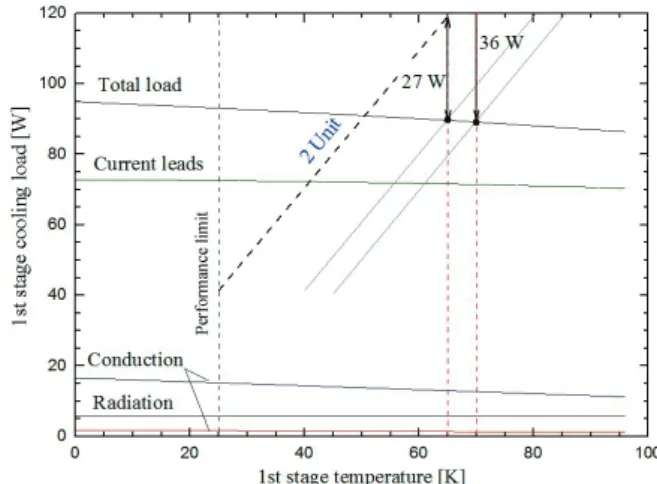
The estimated cryogenic load of the system is summarized in Table III. The cooling loads at each stage depend on the temperature of the first stage, as shown in Fig. 4 and Fig. 5. The dotted line in the figures is the total cooling power of the cryocooler, depending on the number of the cooler. Total load is the summation of each load:
support conduction, thermal radiation, current lead, and helium port conduction. The thermal shield between vacuum and helium vessel is thermally connected onto the first stage cold head of the cryocoolers. Therefore, temperature gradient along the shield is inevitable and the TABLEI
MAIN PARAMETERS OF LTS QUADRUPOLE MAGNETS.
Parameters LQ1 (2)
Pole tip radius 180 mm
Effective length ~550 (~900) mm
Yoke length 450 (800) mm
Yoke outer diameter 1000 mm
Pole end chamber Width: 200 mm, Angle: 60°
Field gradient 15 T/m
Pole tip field 2.7 T
Operation current ~ 160 A
Coil cross section ~2100 mm2
Bmax on coil ~ 4.1 T
Stored energy 310 (480) kJ
Fig. 2. Quadrant cross section of LTS quadrupole magnet (unit: mm).
Fig. 3. Conceptual view of quadrupole magnet cryostat integrated with cryocoolers (unit: mm).).
63
Design of Cryostat for Superconducting Quadrupole Magnets in In-Flight Fragmentation Separator
highest temperature of the shield is approximately 70 K.
When the temperature of first stage is 70 K, the cooling loads are 91.6 and 2.32 W at first and second stage, respectively. The cooling capacity at first stage of cryocooler depends on the temperature of the first stage.
When two cryocoolers are employed the total cooling power of cryocoolers is 120 W at 65 K. It is worthwhile to note here that the total heat load at each stage matched the refrigeration capacity of two Gifford-McMahon (GM) cryocoolers (RDK-415D [5]) with sufficient margin as indicated dotted-line in Fig. 4 and Fig. 5.
3.2. Cryostat and Cryocooler Assembly
The cryostat for the superconducting quadrupole magnet is composed of a liquid helium vessel, enclosing the liquid helium to be stored. The thermal shield made of copper plate between outer vacuum vessel and liquid helium vessel is thermally connected onto the first stage of the cryocoolers, as shown in Fig. 3. The uniform temperature along the shield contributes to promote cooling efficiency [6]. Therefore, the outer vessel contains high vacuum and
several layers of aluminized multilayer insulation is accommodated in an annular space around the curved shield. The temperature distribution was calculated, showing that the highest temperature in the thermal shield is 70 K when the material and thickness of shield are copper and 5 mm, respectively.
The current lead is one of the key components in the LTS quadrupole magnet system since the heat leakage through the leads is a major factor in the heat budget, as shown in Table III. The current lead is designed for optimal thermal heat load performance when carrying operational current with a margin. The current lead was composed of a copper lead and HTS lead. The joint between the copper and HTS lead as well as the HTS lead and superconducting coil are directly cooled by the first and second stage cold head of cryocoolers, respectively.
Since the joint of the copper and HTS lead is cooled by the first stage of cryocoolers, the possible thermal intercept temperature range could be 30-80 K, depending upon the capacity of the cryocooler.
The minimum heat load per unit current (Q/I) of copper TABLEII
MAIN PARAMETERS OF COOLING SYSTEM.
Description Unit
Vacuum vessel
Material Stainless steel 316 -
Outer diameter 1400 mm
Length 3000 mm
Thickness 12-15 mm
Warm bore diameter 260 mm
Thermal shield
Material Copper -
Outer diameter 1150 mm
Length 2800 mm
Thickness 5 mm
Cooling Conduction cooling -
Helium vessel
Material Stainless steel 316 -
Outer diameter 1050 mm
Length 2600 mm
Thickness 12 mm
Cryocooler
Model RDK-415D [5] -
Number of cooler 2 set
TABLEIII
CRYOGENIC LOAD OF CRYOSTAT (FIRST STAGE:70K, UNIT:W)
Parameters Parameters Value
First Stage Support conduction 12.9
(70 K) Thermal radiation 5.64
Current lead 71.59
Helium port conduction 1.37 Residual gas conduction 0.14
Total 91.6
Second Stage Support conduction 0.56
(4.2 K) Thermal radiation 0.08
Current lead 1.03
Helium port conduction 0.65 Residual gas conduction 0.0005
Total 2.32
Fig. 4. First stage cryogenic load as a function of first stage temperature (2 unit means two cryocoolers).
Fig. 5. Second stage cryogenic load as a function of first stage temperature. When two cryocoolers are employed approximately 0.7 W of cooling margin is available (first stage temperature: 70 K).
64
Y. S. Choi, H. M. Chang, B. Baudouy, D. G. Kim, and J. W. Kim
is lower than those of other alloys [7-9] and it is approximately constant for temperature 30-80 K. The optimal lead parameter is strongly dependent on the thermal properties of material. The minimum heat load per unit current of phosphorus deoxidized copper is 0.043 W/A when the optimal lead parameter (L/A: Length/Area) [10] is 12.65 mm-1. For the HTS lead, the CryoSaver current lead from HTS-110 (model CS025030) [11] is selected in the LTS quadrupole magnet system.
3.3. Support Link
The superconducting coil and iron yoke is completely immersed in liquid helium in the liquid helium vessel. The helium vessel (8.6 tons) containing superconducting coil and iron yoke is designed to be suspended from the outer vacuum vessel with vertical suspension and transversal support links on each side, as shown in Fig. 6. The suspension rod and strap type is employed for gravitational and lateral supports, taking into account the thermal contraction and the shortest load path for structure integrity.
The length of the transversal support can be adjusted from the outside of the vacuum vessel to align the superconducting coils with respect to the beam line.
The support links have a heat intercept point, resulting from the thermodynamic optimization of required cooling
power. It is connected to the thermal shield with several flexible copper braids. The prototype of strap support links are made using Zylon [12] fiber for performance test. We did test several times and found out that the breaking point was near the link as shown in Fig. 7. It was observed that the tensile strength was varied with respect to the number of turn, and a support link with 120 turns of Zylon fiber endured more than 10 tons. Based upon the test result, the support link with Zylon fiber will be applied to the cryostat for quadrupole magnets.
4. CONCLUSION
The design of the cryocooler type cryostat for quadrupole triplet magnet in the in-flight fragmentation separator has been presented. The required refrigeration power of cryocooler was determined, resulting from the cryogenic loads estimated by a relevant analysis. The current lead, composed of resistive and HTS lead, was optimized in order to minimize thermal heat load during magnet charging. The strap type support links were employed to suspend heavy cold mass and tensile strength test showed that they could support cold mass including iron yoke. A necessary modification will be incorporated into the final design of cryostat, which will be tested before installation into a heavy ion accelerator facility.
ACKNOWLEDGMENT
This work was supported in part by the Rare Isotope Science Project in Institute for Basic Science funded by the Ministry of Science and the global research collaboration and networking program of NST.
REFERENCES
[1] J. K. Ahn, S. I. Bak, Y. Blumenfeld et al., “Overview of the KoRIA facility for rare isotope beams,” Few-Body Syst. vol. 54, pp.
197-204, 2013.
[2] J. W. Kim, “Status of the rare isotope science project in KOREA,”
Proc. of LINAC 2012, pp. 455-457, 2013.
[3] G. K. White, Experimental techniques in low-temperature physics, 3rd ed., Oxford: Clarendon, 1987, pp. 127–156.
[4] J. W. Ekin, Experimental techniques for low-temperature measurements, 1st ed., Oxford University Press, 2006, pp. 49–86.
[5] Sumitomo Heavy Ind., "Sumitomo product documentation,"
Allentown, PA [Online]. Available: http:// www.shicryogenics.com [6] Y. S. Choi, T. A. Painter, W. D. Markiewicz, B. S. Lee, and H. S.
Yang, “Closed-loop cryogenic cooling for a 21 T FT-ICR magnet system,” IEEE Trans. Appl. Supercond. vol. 18, no. 2, pp.
1471–1474, 2008.
[7] A. F. Clark, G. E. Childs, and G. H. Wallace, “Electrical resistivity of some engineering alloys at low temperature,” Cryogenics, vol. 10, pp. 295–305, 1970.
[8] N. J. Simon, E. S. Drexler, and R. P. Reed, “Properties of copper and copper alloys at cryogenic temperature,” National Institute of Standard and Technology Monograph 177, U.S. Government Printing Office, Washington, D.C., pp. 7-16, 1992.
[9] Copper Development Association Inc., “Low temperature properties of copper,” New York, NY [Online]. Available:
http://www.copper.org
[10] Y. S. Choi, T. A. Painter, D. L. Kim, H. S. Yang, and B. S. Lee,
“Semi-retractable current lead cooled by a cryocooler for high field Fig. 6. Vertical cut view of quadruple magnet cryostat.
Fig. 7. Apparatus for tensile test of support link and picture of support link after tensile test.
65
Design of Cryostat for Superconducting Quadrupole Magnets in In-Flight Fragmentation Separator
magnet,” IEEE Trans. Appl. Supercond. vol. 19, no. 3, pp.
2210–2213, 2009.
[11] HTS-110 Co., “HTS-110 product documentation,” Westborough, MA [Online]. Available: http://www.hts-110.com
[12] L. Seely, M. Zimmerman, and J. McLaughlin, “The use of Zylon fibers in ULBD tendons,” Advances in Space Research, vol. 33, pp.
1736–1740, 2004.
66
![Fig. 1. Schematic layout of heavy ion accelerator facility from [2]. (ECR-IS: Electron Cyclotron Resonance-Ion Sources, RFQ: Radio Frequency Quadrupole, MEBT:](https://thumb-ap.123doks.com/thumbv2/123dokinfo/5380337.410284/1.892.461.806.627.876/schematic-accelerator-facility-electron-cyclotron-resonance-frequency-quadrupole.webp)