pISSN 1229-3008 eISSN 2287-6251
Progress in Superconductivity and Cryogenics
Vol.17, No.1, (2015), pp.28~31 http://dx.doi.org/10.9714/psac.2015.17.1.028
```
1. INTRODUCTION
A heavy ion accelerator complex to produce rare isotope beams for nuclear science users has been designed in Korea [1]. Isotope beams will be produced by using both in-flight fragmentation and isotope on line (ISOL) methods [2].
The maximum beam power is set to be 400 kW, and the maximum energy of 238U beam is 200 MeV/u and about 600 MeV for proton. The 238U beam energy will be increased to 400 MeV/u in the future. The in-flight separator is a magnetic analysis system employing energy degrader to remove unwanted beams and to identify an isotope beam of interest [3]. It consists of superconducting dipoles and large-aperture quadrupoles for momentum dispersion and focusing of a large-emittance beam. The magnets are mostly of superferric type operating at 4 K except for the ones in the front end of the separator. The quadrupole design has been optimized in the aspect of reducing harmonic fields, and prototyping is in progress.
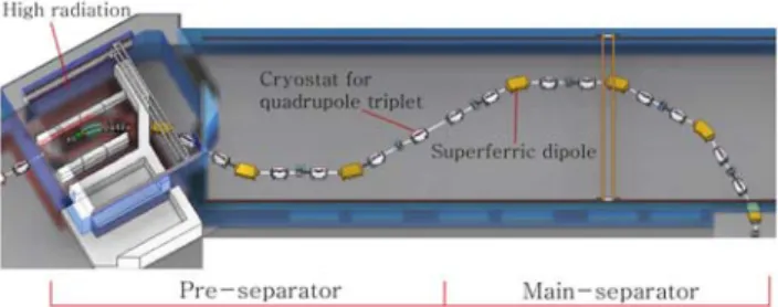
The layout of the in-flight separator is shown in Fig. 1.
The separator is divided into the pre and the main stages.
The front end of pre-separator includes a target to produce isotope beams and a beam dump to stop unwanted beams.
The resulting high radiation heating in the area requires efficient removal of heat from superconducting coils. The total heat load on superconductors is estimated to be over 500 W at the primary beam power of 400 kW. The use of HTS coil with a coolant of cold He gas in 20-50 K and warm iron yoke was chosen considering the design study in
Fig. 1. Layout of the in-flight separator. Array of cryostats of quadrupole triplets and dipole magnets are shown. The high radiation area, where the target and beam dump are located, is indicated.
reference [4].
We have wound HTS coils together with a group of KERI and tested it in a dewar equipped with cryocooler. A full-scale prototype quadrupole, which has cooling channels for the forced flow of cold He gas, will be constructed to ensure its performance in realistic situation.
The magnetic designs of dipoles for both types of using LTS and HTS coils have been performed. We plan to reflect the test results of quadrupole prototypes in their final designs.
2. SUPERFERRIC QUADRUPOLE WITH LTS COIL 2.1. Design optimization
Large aperture quadrupoles are needed to accept over 90 % of rare isotope beams produced at the production
Superconducting magnet system of in-flight separator for a heavy ion accelerator planned in Korea
J. W. Kim*,a, D. G. Kima, H. C. Joa, Y. S. Choib, S. H. Kimc, K. D. Simd, and M. H. Sohnd
aInstitute for Basic Science, Daejeon, Korea
bKorea Basic Science Institute, Daejeon, Korea
cChangwon National University, Changwon, Korea
dKorea Electrotechnology Research Institute, Changwon, Korea
(Received 20 January 2015; revised or reviewed 10 March 2015; accepted 11 March 2015)
Abstract
An in-flight fragment separator, which aims to produce and study rare isotopes, consists of superferric quadrupole triplets and 30° dipole magnets to focus and bend the beams for achromatic focusing and momentum dispersion, respectively. The separator is divided into pre and main stages, and we plan to use superconducting magnets employing high-Tc superconductor (HTS) coils in the pre-separator area, where radiation heating is high. The HTS coils will be cooled by cold He gas in 20-50 K, and in the other area, superferric magnets using low-temperature superconductor (LTS) will be used at 4 K. A few LTS coils were wound and successfully tested in a LHe dewar, and the design of cryostat has been optimized. Development of the HTS coils is ongoing in collaboration with a group at KERI. An HTS coil of racetrack shape was wound and tested in a LN2 bath and in a dewar with cryocooler. No degradation on critical current due to coil winding was found.
Keywords: Superferric magnet, HTS quadrupole, Harmonic field
* Corresponding author: [email protected]
J. W. Kim, D. G. Kim, H. C. Jo, Y. S. Choi, S. H. Kim, K. D. Sim, and M. H. Sohn
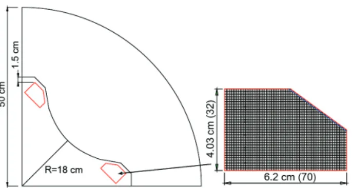
Fig. 2. Dimensions of the quadrupole magnet and its coil dimensions in cross sectional view.
TABLE I
PARAMETERS OF LTS QUADRUPOLE MAGNET.
Item Value
Max. B gradient 15 T/m
Bmax on coil 4.1 T
Jmax 150 A/cm2
Wire size 1.26 x 0.86 mm2
Ic (4.2K, 4T) 400 A
Max. Iop 169 A
Pole tip radius 18 cm Yoke length Q1, Q2 45 cm, 80 cm Yoke outer diameter 100 cm
target. The aperture size of superferric quadrupole is limited by its required maximum focal strength and saturation field of iron pole tip. The iron yoke is placed in the same LHe tank together with the coils. The shape of the pole tip is nearly hyperbolic.
The design of superferric quadrupole was optimized in view of minimizing intrinsic harmonic fields of dodecapole and 20th pole fields in the full operation range of 5-15 T/m [5]. The location and the shape of the coil were the main optimization parameters. Field calculation in 3D has been performed using OPERA3D [6]. The coil was shaped to be trapezoidal so as to place it close to the pole as shown in Fig.
2. The field integral ratio of dodecapole relative to quadrupole at the radius of 12 cm is less than 5×10⁻³, and the ratio of 20th pole is less than 4×10⁻⁴.
Sectional view of the prototype quadrupole is shown in Fig. 2, and its main parameters are listed in Table 1. The coil is of racetrack type. The operating current is designed to be around 40% of the critical current.
2.2. Coil test
The first coil, which was wet wound with Stycast epoxy, was tested in a LHe dewar as shown in Fig. 3.
Electromagnetic expansion force on the straight section is supported by aluminum bars, which pushes the section against the aluminum frame.
The coil currents measured at quenches are shown in Fig.
4. The first quench occurred prematurely, and the following quenches occurred well over the maximum operating current. The same coil was also tested in a dewar cooled by a two-stage cryocooler with cooling capacity of 3 W at 4.5
Fig. 3. Left: The coil fixed to a rigid frame to be dunked into a LHe dewar. Right: Upper plate of the dewar frozen during cool down.
Fig. 4. Maximum operation and quench currents versus maximum magnetic field on the coil. The blue line is the critical current versus the magnetic field of superconducting wire, which is provided by its manufacturer.
K. During coil excitation the current ramping rate was adjusted to control AC heating, measuring temperature on the coil surface. The quench currents measured were over 65% of the critical current, and the lowest temperature measured was around 5.9 K at the quench due to limited conduction cooling. These tests proved the coil package is structurally sound.
2.3. Quadrupole triplet design
The large aperture compared to the length of the quadrupole makes its fringing field effect significant on beam optics. An assembly of quadrupole magnet triplet is shown in Fig. 5, and the location of hexapole coils is indicated. The three magnets will be aligned with tolerance of less than 0.1 mm by four cylindrical pillars and four support bars outside of the yoke. Its mechanical structure is designed to support the total weight of around 10 tons, and the maximum static deflection is calculated to be roughly 0.05 mm.
29
Superconducting magnet system of in-flight separator for a heavy ion accelerator planned in Korea
Fig. 5. Sectional views of the quadrupole magnet triplet.
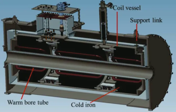
Fig. 6. Cut view of the cryostat using cryocoolers.
We have designed a test cryostat, which uses two units of two-stage cryo-coolers, for quench test of the quadrupole triplet and for extensive field mapping without relying on LHe supply. The total heat load to 4.5 K is less than 3 W.
Detailed design has been carried considering current lead connections and support links for the coil vessel and the radiation shielding structure made of copper. Sectional view of the cryostat is shown in Fig. 6.
2.4. Magnetic field mapper
To operate an in-flight separator with ion beams, accurate field maps in 3D are required at different excitations of quadrupole magnets. The mapper is designed for rapid measurement along the entire length of the triplet.
A Hall sensor is located on the cart driven by precision stepping motors. Field maps in 3D of magnetic multipoles can be extracted from 2D field measured at a single radius of a cylinder [7].
The field mapper under design is shown in Fig. 7. The tube supporting the cart of a Hall probe is made of carbon glass with elastic modulus of around 180 GPa to keep the deflection at the center much less than 0.1 mm. The cart is moved by strings azimuthally and along the axis, and its location is encoded with an accuracy better than 0.1°, 0.01 mm.
Fig. 7. Design of the magnetic field mapper for quadrupole triplet in a cryostat.
3. SUPERFERRIC QUADRUPOLE WITH HTS COIL The front end of the separator exposed to high radiation is shown in Fig. 8. We plan to employ six units of quadrupole magnets and one unit of dipole magnet using HTS coils. The pole and yoke steels are located in room temperature to reduce cold mass in the environment of high radiation heating. The steel components will be water cooled.
Major parameters of an HTS quadrupole prototype are listed in Table 2. Stainless steel (STS) tape of 0.05 mm thick is used to strengthen the coil package and as a part of quench protection.
Fig. 8. Layout of HTS magnets in the front end of pre-separator. The shielding walls for radiation protection are roughly drawn.
TABLE II
PARAMETERS OF HTS QUADRUPOLE PROTOTYPE.
Pole tip radius 130 mm
Yoke length 480 mm
Max. Field gradient 15 T/m
Jmax 140 A/mm2
Imax 370 A
Turn insulation (SUS) thickness 0.05 mm
B//c 2.1 T
Max stored energy 70 kJ
30
J. W. Kim, D. G. Kim, H. C. Jo, Y. S. Choi, S. H. Kim, K. D. Sim, and M. H. Sohn
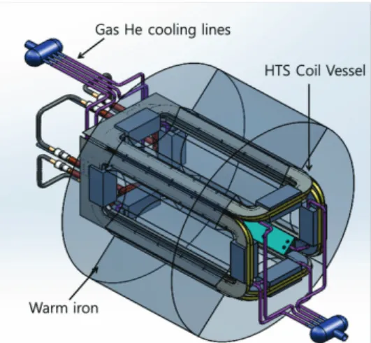
Fig. 9. Design of the cold He gas cooling system for a prototype HTS quadrupole.
The full-scale prototype of HTS quadrupole with four coils inside a coil vessel that is cooled by forced-flow cold He gas, will be fabricated as shown in Fig. 9. The maximum cooling capacity was decided to remove the maximum heat density of 10 mJ/cm3.
The test of the prototype is crucial in evaluating the capability of heat removal and quench safety. The radiation heating will be simulated by an array of heaters located around the coil.
A test coil was wound with 2nd generation 12 mm-wide ReBCO wire manufactured by SuNam Inc. as shown in Fig 10. There is one bridge-type joint inside the coil. The first test was performed in a LN2 bath and then in a dewar with cryocooler down to 40 K. In the beginning we placed little electrical insulation on the coil bobbin as we try to avoid organic material in high radiation environment considering degradation of electrical properties by radiation. Coil excitation test showed that considerable amount of current flew to ground during excitation, and it took more than 1 hr to reach the final field strength, which was not acceptable.
Kapton film was then attached on the bobbin. Figure 11 shows the coil voltage and the magnetic field measured on the coil surface at 50 K. With ground insulation the quench current was similar to the critical current of the HTS.
Radiation-resistant ground insulation will be used.
Fig. 10. An HTS coil wound by a group of KERI.
Fig. 11. Induced voltage on the coil with inductance of 47 mH versus current at the ramping rate of 0.5 A/s. The magnetic fields shown as dotted lines were measured on the coil surface.
4. CONCLUSION
An LTS superferric quadrupole using cold iron with the pole tip radius of 18 cm was optimized in the view of minimizing harmonic fields. Four LTS coils were wound and tested at 4 K. The operation current is designed to be below 40 % of the critical current, and quench currents reached over 80 %. A prototype quadrupole triplet and its cryostat will be completed in 2015. An HTS coil was wound and tested in 40-77 K. The coil will be also tested with forced-flow He gas cooling system down to 20 K, and quench propagation will be tested using heaters and voltage taps. A full-scale An HTS quadrupole prototype will be completed in 2016 for comprehensive tests.
ACKNOWLEDGMENT
This work is supported by the Ministry of Science, ICT and Future Planning (MSIP) and Technology and the National Research Foundation (NRF) of the Republic of Korea under Contract 2011-0032011.
REFERENCES
[1] J. Kim, “Status of the rare isotope science project in Korea,” Proc.
of the 26th LINAC Conf., pp. 455-457, 2012.
[2] J. Kim, D. Kim, M. Kim, J. Song, C. Yun, and S. Kim, “Design study of in-flight fragment separator for rare isotope science project in Korea,” Proc. of Heavy Ion Accel. Tech., pp. 20-22, 2012.
[3] D. Morrissey, B. Sherrill, “In-flight separation of projectile fragments,” Lecture Notes in Physics, vol. 651, Springer-Verlag, Berlin 2004, pp. 113-135.
[4] R. Gupta, M. Anerella, A. Ghosh, J. Schmalzle and W. Sampson,
“Design, construction and test results of a warm iron HTS quadrupole for the Facility for Rare Isotope Beams,” IEEE Trans.
on Appl. Supercond., vol. 18, pp. 236-239, 2008.
[5] A. Zaghloul, D. G. Kim, J. Y. Kim, M. J. Kim, M. Kim, C. Yun, J.
W. Kim, “Design of large aperture superferric quadrupole magnets for an in-flight fragment separator,” AIP Conf. Proc. vol. 1573, pp.
416-421, 2014.
[6] OPERA3D is a product of Cobham PLC.
[7] H. Takeda, T. Kubo, K. Kusaka, H. Suzuki, N. Inabe, J. Nolen,
“Extraction of 3D field maps of magnetic multipoles from 2D surface measurements with applications to the optics calculations of the large-acceptance superconducting fragment separator BigRIPS,” Nucl. Instru. Methods B, vol. 317, pp. 798-809, 2013.
31