* 휴니드 ([email protected])
+ 교신저자, 충북대학교 기계공학부 ([email protected]) 주소: 361-760 충북 청주시 흥덕구 내수동로 52
Design of a Controller for Enhancing Positioning Performance of a PZT Driven Stage
J. S. Park*, Kyuwon Jeong+
(논문접수일 2012. 04. 03, 수정일 2012. 05. 10, 심사완료일 2012. 05. 15)
PZT 구동 스테이지의 위치 제어 성능 향상을 위한 제어기 설계
박종성*, 정규원+
Abstract
This paper describes a new robust control algorithm which can be used to enhance the positioning performance of an ultra-precision positioning system. The working table is supported by flexure hinges and moved by a piezoelectric actuator, whose position is measured by an ultra-precise linear encoder. The system dynamics is very complicated because the movement of the table is governed by both the mechanical characteristics and those of the PZT actuator. So that, the dynamics of the stage was modeled roughly in this paper, and the overall system was formularized to solve the small gain problem.
A series of experiments was conducted in order to verify the usefulness of the proposed algorithm. From the experimental results, the positioning performance such as the accuracy, the rise time and the hysteresis nonlinearity were greatly improved.
Key Words : Ultra-precision stage(극초정밀 스테이지), Flexure hinge(탄성힌지), Piezoelectric actuator(압전구동기), Hysteresis(히스테 리시스), Robust control(견실제어), Feed-forward compensator(앞먹임보상기)
1. Introduction
Ultra precision positioning systems are used in many industrial fields. In order to produce optical parts a mirror surface is essential, which is fabricated by a diamond turning machine. The fast tool servo of the machine is usually actuated by a piezo (PZT) actuator. Similar stages are also adopted in lithography equipment used for semiconductor fabrication or Atomic Force Microscope (AFM) for measuring shapes at nanometer resolution. Such ultra-precision positioning systems are composed of a table guided by flexure hinges and linkages to provide smooth and continuous movement, a piezoelectric
actuator which has rapid response and high resolution and a displacement measuring device such as an ultra-precision linear encoder or a laser interferometer(1~4).
The performances of these positioning systems are mainly determined by the properties of the actuator used. A PZT actuator is used in many systems that need a high frequency response and a simple controller. However, the major limitation of the actuator is its lack of accuracy because of hysteresis and creep phenomena inherent to piezoelectric ceramic materials, which are controlled by the applied voltage. Due to these non-linearities, ultra-precision positioning accuracy cannot be obtained by an open loop control method. Accordingly, a PID
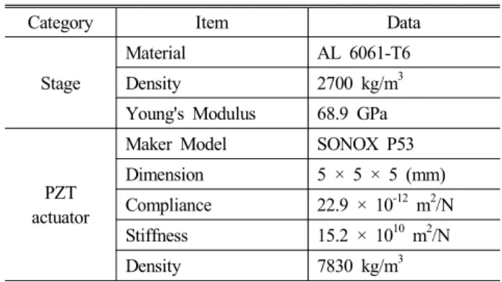
Table 1 Specifications of the system
Category Item Data
Stage
Material AL 6061-T6
Density 2700 kg/m3 Young's Modulus 68.9 GPa
PZT actuator
Maker Model SONOX P53 Dimension 5 × 5 × 5 (mm) Compliance 22.9 × 10⁻¹² m2/N Stiffness 15.2 × 10¹⁰ m2/N Density 7830 kg/m3
Fig. 2 Typical open loop response for the experimental ultra precision positioning system
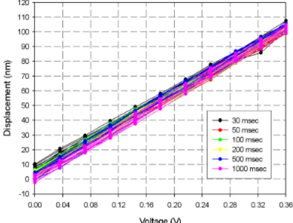
Fig. 3 Total hysteresis result with respect to acquisition time variation for full range in micrometer scale
Fig. 1 Overview of the experimental ultra-precision stage (proportional integral derivative) controller has been adopted for a commercialized system. However, the position tracking performance of the PID controller shows slow response and a large overshoot. Moreover, a tedious task of gain tuning is required.
Many researchers have tried to model the characteristics of a piezoelectric actuator. However, those models were very complicated or unable to describe the behavior exactly. Although much research has been carried out to enhance the performance of positioning stages, the positioning accuracy, especially in nano-meter resolution, is not satisfactory(5~15).
In this paper, a new controller has been designed in order to enhance the position resolution and tracking performance and a series of experiments was conducted with the resulting ultra-precision positioning system. The system, including the actuator, was modeled by a 4th order linear model based upon the frequency response obtained from the sinusoidal input and output. Several weighting functions were selected to satisfy the design specifications and an ∞ controller with a feed-forward compensator was designed.
2. An ultra precision positioning system
2.1 System configuration
The ultra-precision positioning system used in this paper was composed of three parts; an ultra-precision stage, a PZT piezoelectric actuator and an ultra-precision displacement sensor, used to measure the displacement of the stage. The moving part of the stage is supported by a symmetric double parallelogram mechanism with notched flexural hinges in order to reduce the motion errors caused by the manufacturing process and the installation of the actuator. The piezoelectric actuator was a model SONOX P53 made by Ceramtec Inc.(16)
and the displacement sensor was a LIP382 by Heidenhain Inc.
Fig. 1 shows the overall system and the specifications are listed in Table 1.
2.2 System modeling
Fig. 2 shows a typical open loop response to a step voltage input, which is very much complicated one compared with that of a common servo system. It rises very fast and there is a dramatic oscillatory motion in the early response. However, it moves slowly and continuously at the later times and does not stop completely, a phenomenon called creep.
Fig. 4 Total hysteresis result with respect to acquisition time variation for nanometer scale
Fig. 5 Block diagram of the suggested ∞controller with a feed-forward compensator
G(s) W3(s) W1(s)
K(s) u1
u2 +
- e
uT y
y1a
y1b
y2 Controller
Augmented Plant, P(s)
y1
uFB KFF
uFF
+
+ G(s) W3(s)
W1(s)
K(s) u1
u2 +
- e
uT y
y1a
y1b
y2 Controller
Augmented Plant, P(s)
y1
uFB KFF
uFF
+ +
Fig. 6 Block diagram of the ∞ closed loop control with the feed-forward compensator
In order to discover the effect of the above characteristics on the positioning accuracy of the stage system, a series of experiments were conducted for step inputs similar to an upward and downward staircase. Because the position at later times consists of slow movement, as mentioned previously, it is varying as the time the data are acquired. Fig. 3 shows the hysteresis curves with respect to various data acquisition times on the micrometer scale. The maximum displacement variation due to hysteresis was as much as 14 % of the overall path if the stage system was run in an open-loop fashion. As the position acquisition is delayed, the trend line became steeper and the displacement at zero input voltage became small. Typically, the creep displacement is within 0.5 % to 0.8 %. Fig. 4 shows the hysteresis ones on the nanometer scale. In the figure there is about 12 nm variation at the given voltage. Therefore, the uncertainties due to hysteresis and creep are important factors for a positioning system with nano-meter resolution(17~19).
In order to improve the positioning performance in spite of the uncertainties previously described, using a feedback controller could get better performance. In order to do this, the system was modeled roughly as a 4th order linear one. After that, robust controller design method were applied. The ∞
controller with a feed-forward compensator is suggested in order to give robustness for the modeling errors, sensor noises and uncertainties of the actuator and enhance the dynamic tracking performance.
2.3 Design of a controller
In spite of the many previous researches, the performance at nanometer resolution has still not been satisfactory. In this paper, an ∞controller with a feed-forward compensator has been suggested to enhance the dynamic tracking performance and positioning accuracy, as shown in Fig. 5.
In the feed-forward compensator loop, the control voltage,
is a linear function of the desired displacement r(t), that is, . In the feedback control loop, the desired displacement is compared with the measured displacement of the stage system, and the error signal is sent to the ∞controller to compute the additional control output voltage . This voltage is added to the feed-forward control voltage and sent to the piezoelectric actuator which is installed in the stage system. The control output for this controller is defined by Eq. (1).
(1)
In order to design the ∞controller with a feed-forward compensator, we configured the structure of the two-port descriptor system with weighting functions and a feed-forward compensator as shown in Fig. 6. In the figure, the relationships between the inputs and the outputs are represented as follows.
(2)
(3)
(4)
(5)
In order to design the controller, the matrix form of the transfer function, as defined in Eq. (5), must be transformed into the state-space representation. Equation (4) was transformed into
(6)
where
and
are the state vector and the output vector of the plant, . Also,
, and
, are the state and output vectors of and , respectively. The state-space matrix form in Eq. (7) can be obtained.
(7)
The general block diagram of the ∞control is shown in Fig. 6. The plant and controller were included in the figure. The inputs of the plant can be divided into a control input and external input. The control input, is the output of the controller and drives the plant. The external input, represents the combination of the command signal, sensor noises and external disturbance. The output of the plant, is the measured and feedback signal and represents the variables to be regulated, such as error, control input and output(20).
From Eq. (7), the relationship between the control variable
and the external input is defined by Eq. (8).
(8)
From Eq. (8), the ∞control problem is to find the controller
so that
∞is kept smaller than the given reference
as in Eq. (9).
∞≤ (9)
In order to solve this optimization problem, the iteration algorithm was applied until the minimum , which satisfied Eq. (9), was obtained. The required specifications for the ∞ controller were defined as follows. The sensitivity function,
must satisfy the condition of Eq. (10) in the low-frequency region so as to reduce the influence of the output disturbance and so improve the performance of the command tracking.
Also, the complementary sensitivity function, must satisfy the condition of Eq. (11) in the high-frequency region so as to reduce the influence of the sensor noise.
≤ (10)
≤ (11)
where the sensitivity function, and the complementary sensitivity function, are defined in Eq. (12).
(12)
3. Experimental results
3.1 Controller for the experimental stage
The experimental stage system which has nano meter positioning resolution in Fig. 1 was modeled as a 4th order system as follows.
×
×
× ×
(13)
In order to satisfy the required specifications for the open- loop transfer function (13), the weighting functions (14) and (15) were selected.
(14)
(a) Cost function,
(b) Sensitivity function, S(s) and weighting function,
(c) Complementary sensitivity function, T(s) and weighting function,
Fig. 7 Frequency responses of the sensitivity and weighting functions
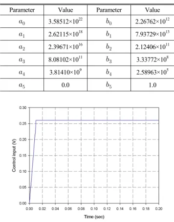
Table 2 Coefficients of the Eq. (16)
Parameter Value Parameter Value
3.58512×10²² 2.26762×10¹²
2.62115×10¹⁸ 7.93729×10¹³
2.39671×10¹⁶ 2.12406×10¹¹
8.08102×10¹¹ 3.33772×10⁸
3.81410×10⁹ 2.58963×10⁵
0.0 1.0
Fig. 8 Feed forward control input by the feed-forward compensator
×
(15)
The feed-forward compensator is a constant 0.26 as obtained from the open loop characteristics. The ∞control synthesis via Gamma iteration optimization was executed in order to compute optimum ∞control laws for a given system,
, via the improved Loop-Shifting two-Riccati formula(20).
The numerical calculation is performed using a Matlab function(21). From the results, the cost function are shown in Fig.
7(a) and the relationship with the sensitivity functions and appear in Fig. 7(b). Also, the relationship of the complementary sensitivity function and appear in Fig. 7(c).
The suggested ∞feedback controller which would be implemented with a feed-forward compensator was designed as Eq. (16) through the ∞ -iteration method.
(16)
3.2 Experimental results for the stage
The performance of the suggested ∞feedback controller with a feed-forward compensator was investigated experimentally.
The feed-forward control input for a 10 nm reference input is shown in Fig. 8. During the initial 0.01sec it was designed as a ramp in order to reduce overshoot.
Fig. 9 shows the hysteresis curve which was compensated by
Command position (nm)
0 10 20 30 40 50 60 70 80 90 100
Displacement (nm)
-10 0 10 20 30 40 50 60 70 80 90 100 110 120
Fig. 9 Compensated hysteresis curve produced by the ∞ controller with a feed-forward compensator
Time (sec)
0 5 10 15 20 25 30 35 40 45 50 55 60 65
Displacement (nm)
-5 0 5 10 15 20 25 30 35 40 45 50 55 60
2 nm
Fig. 10 Experimental results for the continuous step response for the ∞controller with a feed-forward compensator
Time (sec)
0.00 0.05 0.10 0.15 0.20 0.25 0.30 0.35 0.40 0.45 0.50
Displacement (nm)
0 1 2 3 4 5 6 7 8 9 10 11 12 13
PID controller (1) H_inf controller (2) Feedforward/H_inf controller (3) (1)
(2) (3)
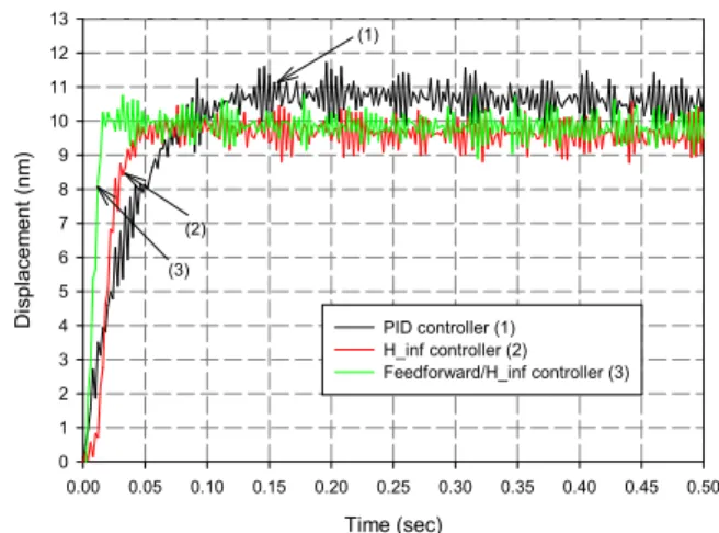
Fig. 11 Comparison of the step response for a PID controller,
∞controller and feed-forward/∞controller
Table 3 Control gains in Eq. (17)
Item Gain value
P-gain (KP) 0.002 ( V/nm ) I-gain (KI) 100449000 ( V/nm․sec ) D-gain (KD) 1500 ( V․sec/nm )
Table 4 Coefficients of the Eq. (20)
Parameter Value Parameter Value
3.361552×10²⁰ 4.659230×10¹⁰
2.457711×10¹⁶ 1.630954×10¹²
2.247254×10¹⁴ 7.835659×10⁹
7.577874×10⁹ 2.212707×10⁷
3.576311×10⁷ 3.110234×10⁴
0.0 1.0
the suggested feedback controller. The error produced by the hysteresis shown in Fig. 4 has been almost eliminated.
Fig. 10 shows the experimental responses for the continuous step inputs for intervals of 5 nm. From the figure the maximum fluctuation of the stage system was proven to be less than ±1 nm and the rise time and settling time were 0.016 s, 0.02 s, respectively. From these results, it can be seen that the positioning accuracy had been improved significantly and the stage system could be controlled adequately at a resolution of 5 nm. In order to demonstrate the enhanced performance, responses for a 10 nm step reference input were obtained using 3 types of controller;
(a) the PID controller, (b) ∞ robust controller and (c) ∞
robust controller with a feed-forward compensator. The results are compared in Fig. 11(19).
The PID controller used in the experiment and the coefficients were as follows.
(17)
For the ∞ robust control experiment, the weighting functions for the robustness and sensitivity were as follows.
(18)
×
(19)
The robust controller, as calculated using the Matlab function, is
(20)
where the coefficients are shown in Table 4.
From the result, the rise times for the PID controller, ∞ robust controller and ∞ robust controller with a feed-forward compensator were 0.08 s, 0.054 s and 0.014 s, respectively.
Also, the settling times with the PID controller, ∞ controller and ∞ controller with a feed-forward compensator were 0.18 s, 0.044 s and 0.014 s, respectively. Therefore, the driving frequency for dynamic tracking control of this system using the suggested ∞controller with a feed-forward compensator was fastest and it was settled very rapidly compared with other controllers.
4. Conclusions
In this paper a new robust control algorithm was proposed for an ultra high precision stage which have nano meter positioning resolution. In order to design the controller, the system transfer function was modeled roughly and a robust feedback controller with feedforward one was designed and implemented. A series of experiments were conducted in order to find the controller performance.
The maximum error due to hysteresis was as much as 14 % of the path covered if the piezoelectric actuator was run in an open-loop fashion. However, The hysteresis non-linearity was almost eliminated and positioning accuracy was greatly improved to below ±1 nm by using the proposed controller.
The rise time was about 14 ms and the response of the system was settled very rapidly. Therefore, the driving frequency of this system could be increased much more than those using other conventional controllers.
Acknowledgement
This work was supported by the research grant of the Chungbuk National University in 2010.
References
(1) Fukukawa, E., and Mizuno, M., 1992, “Piezo-Driven Translation Mechanisms Utilizing Linkages,” Int J.
Japan Soc. Precision Engineering, Vol. 26, No. 1, pp.
54~59.
(2) Croft, D., McAllister, D., and Devasia, S., 1998, “High- speed Scanning of Piezo-probes for Nano-fabrication,”
Journal of Manufacturing Science and Engineering, Vol.
120, No. 3, pp. 617~622.
(3) Lee, D. J., Lee, K. N., Park, N. C., and Park, Y. P., 2005,
“Development of 3-axis Nano Stage for Precision Positioning in Lithography System,” Proc of the IEEE Int. Conference on Mechatronics and Automation, pp.
1598~1603.
(4) Scire, F. E., and Teague, E., 1978, “Piezodriven 50-
Range Stage with Subnanometer Resolution,” Rev. Sci.
Instrum., Vol. 49, No. 12, pp. 1735~1740.
(5) Adriaens, H. J. M. T. A., and Koning, W. L., Banning, R., 2000, “Modeling Piezoelectric Actuators,” IEEE/ASME Trans on Mechatronics, Vol. 5, No. 4, pp. 331~341.
(6) Yang, S., and Huang, W., 1995, “Dynamic Analysis of Piezoelectric Elements,” Rev. Sci. Instrum., Vol. 66, No.
8, pp. 4157~4160.
(7) Goldfarb, M., and Celanovic, N., 1997, “Modeling Piezo- electric Stack Actuators for Control of Micromanipulation,”
IEEE Control Systems, Vol. 17, No. 3, pp. 69~79.
(8) Elka, E., Elata, D., and Abramovich, H., 2004, “The Electromechanical Response of Multilayered Piezoelectric Structures,” Journal of Microelectromechanical Systems, Vol. 13, No. 2, pp. 332~341.
(9) Lerch, R., 1990, “Simulation of Piezoelectric Devices by Two- and Three-dimensional Finite Elements,” IEEE Trans. of Ultrasonics, Ferroelectrics and Frequency Control, Vol. 37, No. 2, pp. 233~247.
(10) Ge, P., and Jouaneh, M., 1996, “Tracking Control of a Piezoceramic Actuator,” IEEE Trans. on Control Systems Technology, Vol. 4, No. 3, pp. 209~216.
(11) Jung, S. N., and Kim, S. W., 1994, “Improvement of Scanning Accuracy of PZT Piezoelectric Actuators by Feed-forward Model-reference Control,” Precision Engineering, Vol. 16, No. 1, pp. 49~55.
(12) Li, C. J., Beigi, H. S. M., Li, S., and Liang J., 1993,
“Nonlinear Piezo-actuator Control by Learning Self-tuning Regulator,” Journal of Dynamic Systems, Measurement, and Control, Vol. 115, pp. 720~723.
(13) Chen, B. M., Lee, T. H., Hang, C. C. , Guo, Y., and Weerasooriya, S., 1999, “An ∞ Almost Disturbance Decoupling Robust Controller Design for a Piezoelectric
Bimorph Actuator with Hysteresis,” IEEE Trans. on Control Systems Technology, Vol. 7, No. 2, pp. 160~174.
(14) Schitter, G., 2004, Stemmer, A., and Allgower, F., 2004,
“Robust Two-degree of Freedom Control of an Atomic Force Microscope,” Asian Journal of Control, Vol. 6, No. 2, pp. 156~163.
(15) Kusakabe, C., Tomikawa, Y., and Takano, T., 1990,
“High-speed Actuation of a Piezoelectric Actuator by Pulse Driving and Stopping of its Residual Mechanical Vibration,” IEEE Trans. of Ultrasonics Ferroelectrics and Frequency Control, Vol. l37, No. 6, pp. 551~557.
(16) Piezosystem Jena, Instruction Manual of Piezo electrical actuator.
(17) Park, J. S., and Jeong, K. W., 2006, “Robust Control for
a Ultra-precision Stage System,” Trans of the KSME (A), Vol. 30, No. 9, pp. 1094~1101.
(18) Jeong, K. W., and Park, J. S., 2009, “Tracking Performance Enhancement of a Nano Resolution Stage,”
Proce. of 2009 KSMTE Fall conference, pp. 374~379.
(19) Park, J. S., 2008, Dynamic Characteristic Analysis and Robust Controller Design of an Ultra Precision Stage System, A Thesis for a Doctorate, Chungbuk National University.
(20) Mackenroth, U., 2004, Robust Control Systems: theory and case studies, Springer, USA.
(21) Mathworks Inc., Matlab Toolbox, Robust Control Toolbox User’s Guide, Mathworks Inc., USA.