Ui
Chapter 4 Movement of Particles by Fluid Flow 4.1 Fluid Flow through Packed Bed of Particles (Chapter 4)
(1) Pressure Drop - Flow Relationship 1) Laminar Flow
Fluid flow through a packed bed: simulated by fluid flow through a hypothetical tubes
∴ ( -
Δ p)
H = 32
μ U
D2
⇒ ( -
Δ p)
He = K1
μ Ui
D2e Hagen-Poiseille equation
Substituting suitable relations for (equivalent height) and
(equivalent diameter)
∴ ( -
Δ p)
H = 180
μ U
x2 ( 1 -
ε )2
ε 3
Carman-Kozeny equation
2) General Equation for Turbulent and Laminar Flow Ergun equation
( -
Δ p)
H = 150
μ U
x2 ( 1 -
ε )2
ε 3 + 1.75
ρ fU2
x ( 1 -
ε )
ε 3
Laminar Turbulent Laminar flow for R e* = xU
ρ f
μ ( 1 -
ε ) < 1 0
Turbulent flow for R e*= xU
ρ f
μ ( 1 -
ε ) > 2000
or
f*= 150Re* + 1.75
where f* ≡ ( -
Δ p)
H x
ρ fU2
ε 3
( 1 -
ε )
Filtrate Filter cake
Slurry
Filter medium
Filtrate Filter cake
Slurry
Filter medium
Friction factor
Figure 4.1
3) Nonspherical Particles
xsv (surface-volume diameter) instead of x
Worked Example 4.1
(2) (Liquid) Filtration
(1) Introduction
Filter media : Canvas cloth, woolen cloth, metal cloth, glass, cloth, paper, synthetic fabrics
Filter aids : To avoid cake plugging
e.g. Diatomaceous silica, perlite, purified woolen cellulose, other inert porous solids
- By either adding slurry (increasing cake permeability) or precoating the filter media surface
1) Incompressible Cake For cake filter
From laminar part of Ergun equation
( -
Δ p)
H = 150
μ U( 1 -
ε )2
x2
ε 3
where L : cake thickness
x : surface-volume diameter of particle
* For compressible filter cake,
dLdp =rc
μ U
where rc: a function of pressure difference
By defining cake resistance rc
rc= 150 ( 1 -
ε )2
x2
ε 3 ,
( -
Δ p)
H =rc
μ U
where U= 1A dV dt
V: volume of slurry fed to filter
Also defining
φ (volume formed by passage of unit volume filtrate)
φ =HA
V , dVdt = A2( -
Δ p)
rc μ
φ V
Including the resistance of filter medium,
since the resistances of the cake and the filter medium are in series,
( -
Δ p) = ( -
Δ pm) + ( -
Δ pc)
↓ A1 dVdt rc
μ Hc
By analogy for the filter medium
(-
Δ pm) = 1A dV
dt rm
μ Hm
∴ ( -
Δ p) = 1A dV
dt (rm
μ Hm+rc
μ Hc)
Defining equivalent height of filter cake and volume of filtrate
rmHm=rcHeq and Heq=
φ Veq
A
whereVeq: volume of filtrate passing to create a cake of thickness Heq
∴ A1 dVdt = ( -
Δ p)A
rc
μ (V+Veq)
φ
Constant rate filtration
A1 dV
dt = ( -
Δ p)A
rc
μ (V+Veq)
φ =constant
Constant pressure filtration Integrating
Vt = rc φ
μ
A2( -
Δ p)
(
V2 +Veq)
Worked Example 4.2
3) Washing the Cake Figure 4.2
4.2 Fluidization (Chapter 5)
(1) Fundamental
*
Δ p vs. U Figure 5.1
Minimum (incipient) fluidization, Umf
From force balance
Net downward force
Δ p= ( 1 -
ε )(
ρ p-
ρ g)H (1)
Net upward force
Δ p
H = 150 ( 1 -
ε )2
ε 3
μ U
x2sv + 1.75 1 - ε
ε 3
ρ gU2
xsv (2) Equating (1) and (2) at U=Umf
Ar= 150 ( 1 -
ε )
ε 3 Remf+ 1.75 1
ε 3 Re2mf
where A r≡
ρ gx3sv(
ρ p-
ρ f)g
μ 2 , Archimedes number
Remf=
ρ fUmfxsv
μ
ε = 0.4, usually
More practically,
Wen and Yu(1966) for xsv > 1 0 0
μ m
Ar= 1056Remf+ 159Re2mf Baeyens and Geldart(1974) for x < 1 0 0
μ m
Umf= (
ρ p-
ρ f)0.934g0.934x1.8
1110
μ 0.87
ρ 0.066f
* Densities of particles
- Absolute density: materials property - Particle density: Figure 5.2
- Bed density
* Sieve diameter, xp , xv= 1.13xp
mea n xp= 1
∑mi/xi
(2) Bubbling and Non-Bubbling Fluidization (5.3) Types of Fluidization
Various types of fluidized beds
- Bubbling fluidized bed : Figure 5.3 for Group B particles
- Liquid fluidization: Figure 5.4
Worked Example 5.1
(3) Classification of Powders (5.4) Geldart(1974) Figure 5.6
Table 5.1
Group A : Nonbubbling for U m f < U < U m b Group B : Bubbling for U > U m f
No maximum in bubble size Group D : Spoutable
Group C : Subject to channeling in large diameter-bed
(4) Applications of Fluidized Beds(5.8) Advantages
- Liquid-like behavior, easy to control and automate - Rapid mixing, uniform temperature and concentration
- Resists rapid temperature changes, hence responds slowly to changes in operating conditions and avoids temperature runaway with exothermic reactions - Circulate solids between fluidized beds for heat exchange
- Applicable for large or small scale operations
- Heat and mass transfer rates are high, requiring smaller surfaces
Disadvantages
- Bubbling beds are difficult to predict and are less efficient
- Rapid mixing of solids causes nonuniform residence times for continuous flow reactors
- Particle comminution(breakup) is common
- Pipe and vessel walls erode to collisions by particles
1) Physical Processes
Drying / Mixing / Granulation / Coating / Heat exchanger/ Adsorption Figure 5.17
2) Chemical Processes Table 5.2
Figure 5.18 Fluidized catalytic cracker
Powder
Rotary valve
Blower
4.3 Pneumatic Transport (Chapter 6)
(1) Pneumatic Transport
- Use of a gas to transport a particulate solid through pipeline
- Three major variables for pneumatic conveying - solid mass flow rate
- gas mass flow rate
- pressure gradient(pressure drop per unit length)
1) Dilute-Phase and Dense-Phase Transport
Dilute-Phase Dense-Phase
High gas velocity (> 20 m/s) Low solids concentration (< 1 % by volume)
Low pressure drop (<5 mbar/m) Short-route, continuous
transport(< 10 ton/h)
Capable under negative pressure Particles behave as individuals Fully suspended in gas Fluid-particle : dominant
Low-gas velocity (1-5 m/s) High solids concentration (> 30 % by volume)
High pressure drop (> 20 mbar/m) Batch or semibatch transport
Not-fully suspended in gas
Much interaction between particles and between particle and wall
2) The Choking Velocity in Vertical Transport Figure 6.1 -
Δ p/
Δ L vs. U (gas superficial velocity)
at various solids flow flux G Static head of solids → friction resistance
Choking velocity, UCH
The lowest velocity at which the dilute-phase transport can operate at G given
Punwani et al (1976) UCH
ε CH -UT= G
ρ p( 1 -
ε CH)
ρ 0.77f = 2250D(
ε - 4.7CH - 1)
[
UCHε CH -UT
]
23) Saltation Velocity in Horizontal Transport Figure 6.2 -
Δ p/
Δ L vs. U(gas superficial velocity)
at various solids flow flux G
Saltation velocity, USALT
The gas velocity at which the solids to begin to settle out Boundary between dilute phase flow and dense phase flow
Rizk(1973) Mp
ρ fUSA L TA =
{
10 ( 14401x+ 1. 96 )} {
USA L TgD}
( 1100x+ 2. 5 )in SIsolid loading Froude number at saltation
where Mp : particle mass flow rate D : pipe diameter
4) Fundamentals
Gas and particle velocity Superficial velocity
Ufs= Qf
A and Ufp= Qp A Actual velocity
Uf= Qf A
ε = Ufs
ε and Up= Qp
A(1 -
ε ) =
Ups 1 - ε
* Slip velocity Uslip
U r el=Uf-Up≡Uslip Continuity
Gas mass flow rate
Mf=AUf
ερ f
Particle mass flow rate
Mp=A Up( 1 -
ε )
ρ p
Solid loading
Mp
Mf = Up( 1 -
ε )
ρ p
Uf
ερ f
Pressure drop
From Newton's 2nd law of motion Figure 6.3
Rate of momentum for flowing gas-solid mixture
= Net force exerting on the mixture
↓ p1-p2= 12
ρ f
ε U2 f + 12
ρ p( 1 -
ε )U2 p + FfwL + FpwL
gas solids gas-wall solids-wall acceleration acceleration friction friction
+
ρ fL
ε gsin
θ +
ρ pL(1-
ε )gsin
θ
gas gravity solids gravity
5) Design for Dilute Phase Transport Gas velocity
Uf ~ 1.5USALT since US A L T >UC H
for systems comprising both vertical and horizontal lines Uf ~ 1.5UCH
for vertical line only
Table. Approximate air velocity for powder transport
Powder U, m/s
Wheat, rice, plastic pellets Grains, limestone powder Soda ash, sugar
PVC powder Carbon powder Cement
Alumina powder Sand
16 - 24 16 - 23 15 - 20 20 - 26 18 - 24 18 - 28 24 - 32 23 - 30
Pipeline pressure drop
FpwL= 0.057GL g
D for vertical transport FpwL= 2fp(1 -
ε )
ρ pU2pL
D = 2fpGUpL
D for horizontal transport where Up=Uf( 1 - 0.0638x0.3
ρ 0.5p ) and
fp= 38
ρ f
ρ p CD D
dp
(
UfU-pUp)
CD: drag coefficient (fn of Rep)
Bend
~ 7.5 m of vertical section pressure drop
* Downflow through vertical-to-horizontal bend : - greater tendency for saltation
- avoided if possible.
* Blinded tee bend : Figure 6.4 with respect to radius elbow - prolonging service life due to cushioning effect - with the same pressure drop and solid attrition rate
Worked Example 6.1
Equipment
Figure 6.5 Positive pressure system Figure 6.6 Negative Pressure system
* Centrifugal blowers(fan) vs. Positive displacement blower low pressure high pressure small amount of dust allowed no dust is allowed
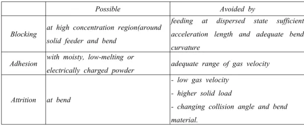
Some problems in pneumatic transport
Possible Avoided by
Blocking at high concentration region(around solid feeder and bend
feeding at dispersed state sufficient acceleration length and adequate bend curvature
Adhesion with moisty, low-melting or
electrically charged powder adequate range of gas velocity
Attrition at bend
- low gas velocity - higher solid load
- changing collision angle and bend material.
6) Dense Phase Transport Flow Patterns
- Horizontal - Figure 6.7
Saltating flow - unstable, bad flow pattern Discontinuous dense phase flow*
Dune Flow / Discrete Plug Flow / Plug Flow*
Continuous Dense Phase Flow - requires high pressure
adequate for short-pipe transport
Equipment
Blow tanks : with fluidizing element (Figure 6.13) without fluidizing element (Figure 6.14) Plug formation : air knife (Figure 6.10)
air valve (Figure 6.11) diaphragm (Figure 6.12) Plug break-up : bypass (Figure 6.8)
pressure actuated valves (Figure 6.9)
Design and Operation
- Use of test facilities + past experience
for pipe size, air flow rate and type of dense phase system - Group A, D better than Group B, C for dense phase conveying - Higher permeability: more suitable for plug flow type conveying - Higher air retention: more suitable for dune mode flow
4.3 Flow of Liquid-Solid Suspension (Slurries)(Supplement)
Characteristics of hydraulic transport Transition velocity
Durand(1953)
Utr= 11.9 (UTD)1/2x1/4 where D: pipe diameter Critical(saltation) velocity
Durand(1953)
Uc=FL[ 2gD(
ρ p/
ρ f- 1)]1/2
where FL: function of x and
ε
Hanks (1980)
Uc= 3.12 ( 1 -
ε )0.186
(
Dx)
1/6[ 2g D(ρ p/
ρ f- 1)]1/2