Accuracy evaluation of metal copings
fabricated by computer-aided milling and direct metal laser sintering systems
Jong-Kyoung Park1, Wan-Sun Lee1, Hae-Young Kim2, Woong-Chul Kim1, Ji-Hwan Kim1*
1Department of Dental Laboratory Science and Engineering, College of Health Science, Korea University, Seoul, Republic of Korea
2Department of Public Health Science, Graduate School & BK21+ Program in Public Health Science, Korea University, Seoul, Republic of Korea
PURPOSE. To assess the marginal and internal gaps of the copings fabricated by computer-aided milling and direct metal laser sintering (DMLS) systems in comparison to casting method. MATERIALS AND METHODS. Ten metal copings were fabricated by casting, computer-aided milling, and DMLS. Seven mesiodistal and
labiolingual positions were then measured, and each of these were divided into the categories; marginal gap (MG), cervical gap (CG), axial wall at internal gap (AG), and incisal edge at internal gap (IG). Evaluation was performed by a silicone replica technique. A digital microscope was used for measurement of silicone layer.
Statistical analyses included one-way and repeated measure ANOVA to test the difference between the fabrication methods and categories of measured points (α=.05), respectively. RESULTS. The mean gap differed significantly with fabrication methods (P<.001). Casting produced the narrowest gap in each of the four measured positions, whereas CG, AG, and IG proved narrower in computer-aided milling than in DMLS. Thus, with the exception of MG, all positions exhibited a significant difference between computer-aided milling and DMLS (P<.05). CONCLUSION. Although the gap was found to vary with fabrication methods, the marginal and internal gaps of the copings fabricated by computer-aided milling and DMLS fell within the range of clinical acceptance (<120 μm). However, the statistically significant difference to conventional casting indicates that the gaps in computer-aided milling and DMLS fabricated restorations still need to be further reduced. [J Adv Prosthodont 2015;7:122-8]
KEY WORDS: CAD/CAM system; Cobalt-chromium alloy; Computer-aided milling; Direct metal laser sintering;
Marginal and internal fit
INTRODUCTION
Metal-ceramic crowns, which consist of a thin metal coping bonded onto abutment teeth and a fused ceramic layer on
top, are widely used for fabricating dental restorations.1 Although precious metal alloys have been used as the primary materials for dental restorations, the rising cost of such materials and the increasing concern amongst patients regarding the expense of dental prosthodontic treatment has encouraged the development of new dental alloys.
Nickel-chromium (Ni-Cr) alloys have been highly favored for use in metal-ceramic crowns. However, despite their high popularity, they have exhibited inherent limitations with regards to the formation of excessive oxides and bio- incompatibility that has led to allergic reactions in some patients. Therefore, cobalt-chromium (Co-Cr) alloys have been suggested as novel alternatives because of their high mechanical strength, corrosion resistance, biocompatibility, and cost efficiency.1-3
Non-precious dental alloys have been used in conjunc-
Corresponding author:
Ji-Hwan Kim
Department of Dental Laboratory Science and Engineering, College of Health Science, Korea University, 145, Anam-ro, Seongbuk-gu, Seoul 136-713, Republic of Korea
Tel. 82 2 3290 5666: e-mail, [email protected]
Received June 30, 2014 / Last Revision September 29, 2014 / Accepted October 1, 2014
© 2015 The Korean Academy of Prosthodontics
This is an Open Access article distributed under the terms of the Creative Commons Attribution Non-Commercial License (http://creativecommons.
org/licenses/by-nc/3.0) which permits unrestricted non-commercial use, distribution, and reproduction in any medium, provided the original work is properly cited.
tion with conventional lost-wax casting techniques to fabri- cate restorations; this has subsequently evolved into meth- ods applicable to automated processing. The adoption of automated systems has in turn facilitated the development of a diverse range of fabrication methods, including the computer-aided milling and direct metal laser sintering (DMLS) systems. The computer-aided milling involves mechanical processing of restorations by subtracting pre- fabricated blanks, while the DMLS incorporates an additive manufacturing (AM) system that fabricates restorations by applying a laser, which selectively melts a metal powder to build up layers of solidified material.4-6 This additive meth- od, also known as selective laser sintering (SLS), has drawn particular attention owing to its capability of preventing distortion and fabrication defects that inherent to conven- tional fabrication methods.7
Ultimately, the marginal and internal fit of a dental res- toration provides the overarching factors for its success and longevity.8 For instance, a superior marginal fit markedly reduces the recurrence of dental caries and development of periodontal diseases, and extends the longevity of the res- toration.9 Furthermore, a superior internal fit is necessary to maintain and support restorations.10
Although numerous metal-ceramic crowns are being widely used clinically, these are typically fabricated by con- ventional means from Ni-Cr alloys, and this was the focus of most previous studies.11-13 Thus, very few studies have provided a comparative assessment of metal copings based on Co-Cr alloys with regards to their marginal and internal fits. Therefore, Co-Cr alloy copings for metal-ceramic crowns were fabricated as part of this study using the latest computer-aided milling and DMLS. Comparative samples were also produced by a conventional lost-wax casting method to verify the extent to which the marginal and internal gaps vary in relation to the fabrication method, as well as to ascertain whether such gaps fall within the range of clinical acceptance. A null hypothesis is established that
“the marginal and internal gaps of restorations will not vary with different fabrication methods.”
MATERIALS AND METHODS
This study selected a maxillary right canine from a typodont resin model (AG-3; Frasaco GmbH, Tettnang, Germany).
The selected resin tooth was prepared with a 1.0 mm cir- cumferential chamfer finishing line, an incisal height reduc- tion of 1.5 mm and a 6° axial inclination. Finally, all sharp edges were rounded off.
To make a stone replica, the resin abutment tooth was first replicated in silicone (Deguform®; DeguDent GmbH, Hanau-Wolfgang, Germany). A type IV stone (GC Fujirock EP; GC Europe N.V., Leuven, Belgium) was then poured into this silicone mold to fabricate a total of 30 working models, i.e., 10 models per group.
To give some internal space for cementation, a die spac- er (Space-It; George Taub Products, Jersey City, NJ, USA) was first applied to the 1 mm upper margin of the abut-
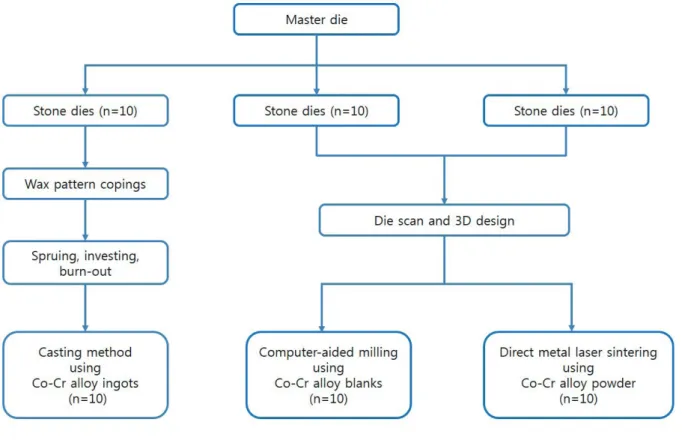
ment teeth working model to a thickness of 25 μm.14 A dip- ping method was then used to fabricate a 0.5 mm thick wax pattern. Next, a plastic sprue was attached to the completed wax coping, which was followed by investing and burn-out.
To ensure a stable casting of the Co-Cr alloys (StarLoy C;
DeguDent GmbH, Hanau-Wolfgang, Germany) (Table 1), a high-frequency casting machine (Fornax® T; Bego, Bremen, Germany) was used (Fig. 1); the investing, burn-out and casting processes were conducted in compliance with the manufacturers’ instructions.
Ten working models were scanned with a 3D laser scan- ner (D800; 3Shape A/S, Copenhagen, Denmark). The mod- els were then used to design the copings using a CAD soft- ware program (Dental DesignerTM; 3Shape A/S, Copenhagen, Denmark). As in the casting, the thickness was 0.5 mm and an internal space of 25 μm was provided from the 1 mm upper margin. The data relevant to the completed design was saved as an STL file, which was in turn fed into a mill- ing machine (Datron D5; Datron AG, Mühltal, Germany).
Metal blanks (KERA®-DISC; Eisen-bacher dentalwaren ED GmbH, Rhine-Main, Germany) (Table 1) were then milled to fabricate the Co-Cr alloy copings (Fig. 1).
In order to fabricate the DMLS copings, the same virtu- al coping design technique was used as stated above with the CAD software program. Then the copings were fabri- cated using a DMLS machine (EOSINT M270; EOS GmbH, Krailling, Germany) (Fig. 1) by fusing Co-Cr pow- der (EOS CobaltChrome SP2; EOS GmbH, Krailling, Germany) (Table 1). The powder was sintered to a layer thickness of 20 μm at a building speed of 2-20 mm3/s from the incisal edge to the margin at 1500ºC in an inert gas environment (nitrogen atmosphere). After sintered, the copings were cooled down to the room temperature in the furnace (decreasing at the rate of 9ºC/m).
The marginal and internal gaps were measured in com- pliance with Holmes et al.15 A total of 14 points were mea- sured, i.e., from a to g mesiodistally and from 1 to 7 labio- lingually, these were broadly divided into the following four categories: (1) marginal gap (MG), a,g,1,7; (2) cervical gap (CG), b,f,2,6; (3) axial wall at internal gap (AG), c,e,3,5; and (4) incisal edge at internal gap (IG), d,4 (Fig. 2).
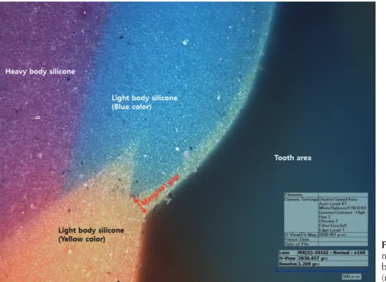
To measure the marginal and internal gaps, a silicone replica technique was used. For this, the fabricated metal- ceramic crown copings were first filled with yellow light- body silicone (Aquasil Ultra XLV; Dentsply Caulk, Milford, DE, USA), and then placed on a stone die and fitted by applying an even finger pressure of 50 N on an electronic scale. Next, the metal copings were carefully separated, with the hardened yellow light-body silicone film produced used to represent the gaps between the copings and the die. To keep bubbles from rising around the margin of the replicat- ed silicone, and to measure the gap with ease, a contrasting blue light-body silicone (Aquasil Ultra LV; Dentsply Caulk, Milford, DE, USA) was then added. As the light-body sili- cone film adhering to the stone die was often too thin to resist tearing or to maintain its shape, it was additionally covered with a strong heavy-body silicone for stabilization
(Aquasil Ultra Monophase; Dentsply Caulk, Milford, DE, USA). Finally, the replicated silicone was cut using a razor blade along the mesiodistal and labiolingual directions, with the thickness of each section examined under a digital microscope at 160× magnification (KH-7700; Hirox, Tokyo, Japan). Digital images were taken with the digital microscope. The images were measured by the internal stored imaging data software (KH-7700 software Ver. 2.10c;
Hirox, Tokyo, Japan) which was equipped to the digital microscope machine (Fig. 3).
The mean gap and standard deviation at each point were compared among the three fabrication methods (cast- ing, computer-aided milling, and DMLS) using a one-way analysis of variance (ANOVA).
Fig. 1. Flowchart for the fabrication of metal copings.
Table 1. Chemical composition of the Co-Cr alloys used (unit: wt%)
Alloy Group Composition
Co Cr W Mo Si Mn Fe Nb
StarLoy C Casting 59.4 24.5 10.0 1.0 1.0 - 0.1 2.0
KERA-DISC Computer-aided milling 61 28 8.5 - 1.65 0.25 0.5 -
EOS Co-Cr SP2 DMLS 61.8-65.8 23.7-25.7 4.9-5.9 4.6-5.6 0.8-1.2 Max. 0.1 Max. 0.5 -
Fig. 2. Schematic diagram of the measuring points (A) mesiodistal section: a,g = marginal gap (MG), b,f = cervical gap (CG) (400 μm above MG), c,e = axial wall at internal gap (AG), d = incisal edge at internal gap (IG).
(B) labiolingual section: 1,7 = MG, 2,6 = CG (400 μm above MG), 3,5 = AG, 4 = IG.
A B
A repeated measures analysis of variance (ANOVA) was the used to evaluate any difference between the three fabri- cation methods with the Greenhouse-Geisser correction method. A type-one error rate of 0.05 was applied in all statistical testing and the statistical software package SPSS Ver. 12.0 (SPSS Inc., Chicago, IL, USA) was used.
RESULTS
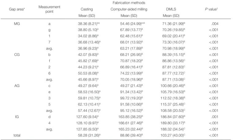
Of the three methods used, the overall mean gap (standard deviation, SD) was lowest for the coping fabricated by the casting method at 58.3 (31.3) μm. This was followed in turn by the computer-aided milling and DMLS methods at 88.9 (39.4) μm, and 103.3 (43.0) μm, respectively, demonstrating a significant difference in the values recorded. Moreover, the cast copings demonstrated the smallest gap at all four of the position categories (MG, CG, AG and IG), whereas those copings made by the computer-aided milling method had a smaller gap than those produced by the DMLS meth- od at CG, AG and IG. However, there was no significant difference observed between the computer-aided milling and DMLS group in the case of the MG (Table 2).
Table 3 shows analysis results comparing the gaps at four different categories. Note that the MG (SD) is the smallest at 57.0 (2.0) μm, with the CG and AG (SD) follow- ing in order as 67.8 (1.7) μm and 87.0 (2.2) μm. The largest gap (SD) of 160.5 (4.9) μm was observed at the IG loca- tion. Statistically significant differences were found between the categories (P<.001).
DISCUSSION
With the advent of automated systems such as computer- aided-design/computer-aided-manufacturing (CAD/CAM), the dental industry has witnessed a series of innovative developments. Compared with conventional casting meth- ods to fabricate dental restorations, these automated meth- ods skip such steps as wax-up, investing, and burn-out, thus simplifying the fabrication in favor of reduced material consumption and greater time efficiency.16 Nonetheless, the marginal and internal fits of dental restorations fabricated with such automated systems are subjected to the effects of multiple factors, including the precision of the scanner used to digitize a working model, the 3D design via com- puter software, and the precision of the machine used to fabricate the 3D design.17
Meanwhile, the 3D design data relevant to the complet- ed design was saved as an STL file. It should be noted here that STL (stereolithography) files were originally developed by 3D Systems Inc. as a default file format for stereolithog- raphy CAD software, and is well known as a “standard tes- sellation language.” As this file format describes the surface structure of a solid 3D model, it is supported by most 3D software products.
The present study compares a conventional casting method to the latest in automated fabrication systems, i.e., the computer-aided milling and DMLS, for the fabrication of copings, using the marginal and internal fit of the result- ing structures as the measure of difference.
Fig. 3. Measurement of the marginal area silicone thickness by digital microscopy
(magnification 160×).
The findings of this study, however, disagree with those of previous studies. For instance, Örtorp et al.18 used a ste- reomicroscope and digital photos to investigate the margin- al and internal gaps of Co-Cr three-unit bridges for posteri- or teeth. Their comparison of the fits of dental prosthesis found that a DMLS led to a narrower gap than with casting, whereas a computer-aided milling produced the widest gap of all. In contrast, Quante et al.19 used a silicone replica technique to examine the marginal and internal gaps of
Co-Cr single copings for posterior teeth under a micro- scope. Through this, they found that the mean marginal gap of a dental prosthesis fabricated by a DMLS at two points was 73 and 76 μm, whereas the internal gap on the occlusal surface was in the range of 252-284 μm. Neither of these findings is consistent with the fact that the gap was observed in this study to increase in the order of casting, computer-aided milling, and then DMLS.
To measure the marginal and internal gap between the Table 2. Relative mean discrepancy of the three fabrication methods (unit: μm, N=10)
Gap area* Measurement point
Fabrication methods
P value†
Casting Computer-aided milling DMLS
Mean (SD) Mean (SD) Mean (SD)
MG a 38.36 (8.21)A‡ 54.46 (24.99)A,B 71.36 (21.99)B .004
g 38.80 (5.10)A 67.89 (13.77)B 70.26 (19.85)B <.001
1 34.02 (8.86)A 62.48 (15.61)B 69.02 (20.41)B <.001
7 36.68 (13.46)A 68.01 (13.92)B 73.30 (16.07)B <.001
avg. 36.96 (9.23)A 63.21 (17.89)B 70.98 (18.99)B <.001
CG b 42.07 (9.83)A 68.21 (26.95)B 88.39 (15.15)B <.001
f 45.82 (7.69)A 70.87 (18.20)B 86.86 (13.56)C <.001
2 44.23 (9.21)A 66.89 (16.41)B 87.81 (12.83)C <.001
6 50.53 (8.08)A 74.22 (13.99)B 87.77 (12.72)C <.001
avg. 45.66 (8.97)A 70.05 (18.96)B 87.71 (13.08)C <.001
AG c 49.27 (9.64)A 49.27 (21.43)B 100.66 (20.46)B <.001
e 58.53 (16.50)A 91.34 (13.42)B 105.79 (16.53)B <.001
3 59.81 (10.75)A 99.72 (19.20)B 112.52 (18.38)B <.001
5 62.13 (10.41)A 91.58 (10.66)B 115.37 (25.48)C <.001
avg. 57.44 (12.67)A 95.12 (16.52)B 108.58 (20.53)C <.001
IG d 127.60 (9.54)A 163.85 (38.25)B 186.84 (37.60)B .001
4 128.10 (9.97)A 166.61 (27.46)B 189.80 (33.17)B <.001
avg. 127.85 (9.50)A 165.23 (32.44)B 188.32 (34.54)C <.001
total 58.28 (31.26)A 88.86 (39.40)B 103.27 (43.00)C <.001
* MG: marginal gap, CG: cervical gap, AG: axial wall at internal gap, IG: incisal edge at internal gap.
† By one-way ANOVA.
‡ Different superscript alphabets in the same row represent significant differences at a type-one error rate of 0.05.
Table 3. Estimated mean gaps for the four different categories of measurement points, averaged in three fabrication methods (unit: μm, N=10)
Gap area* Measurement point Estimated mean (SE)† 95% confidence interval
MG avg. (a,g,1,7) 57.0 (2.0)A‡ 52.9-61.2
CG avg. (b,f,2,6) 67.8 (1.7)B 64.4-71.3
AG avg. (c,e,3,5) 87.0 (2.2)C 82.4-91.6
IG avg. (d,4) 160.5 (4.9)D 150.4-170.6
P value <.001
* MG: marginal gap, CG: cervical gap, AG: axial wall at internal gap, IG: incisal edge at internal gap.
† Estimated mean using the repeated measures ANOVA considering three fabrication methods.
‡ The different letters represent a significant difference at a type-one error rate of 0.05.
prosthesis and abutment teeth, a method of cutting and observation incorporating a silicone replica technique, a visual examination using an explorer and a micro CT mea- surement were suggested.20-23 This method of cutting and observation is suggested as the most accurate approach to enable the direct validation of sections, yet requires that the specimens be broken. This therefore makes it quite hard to measure multiple points, thus requiring many duplicate specimens for extensive measurements. In contrast, the sili- cone replica technique is a non-destructive measurement method, which provides a reliable measure of fit than other methods.21,24 It was therefore selected for use in this study so as to allow repeated measurements at multiple points.
The marginal and internal accuracy of prosthetic com- ponents is important aspect in their longevity. With regards to the marginal gap of dental prosthesis, the ADA specifi- cations25 define the ‘clinical acceptance of bonded prosthesis’
as being less than 25 μm. In practice, however, such gaps are often quite difficult to obtain. According to Assif et al., the mean marginal gap is closer to 140 μm, while Hung et al. suggested a value of 50-75 μm.26,27 Gulker even went so far as to suggest that up to 200 μm should be tolerated.28 Meanwhile, Quante et al.19 and Ucar et al.12 reported 76-93 μm and 62.6 (21.6) μm as the marginal gaps of laser sinter- ing-based fabricated copings, respectively. In short, the clin- ical acceptance of marginal gaps varies quite across differ- ent studies. However, despite this, many previous studies have simply applied the 120 μm marginal gap suggested by McLean and von Fraunhofer as the definition of the range of clinical acceptance.29 In this study, the means of MG were 36.96 (9.23) μm, 63.21 (17.89) μm, and 70.98 (18.99) μm in the order of casting, computer-aided milling, and DMLS, while the means of CG were 45.66 (8.97) μm, 70.05 (18.96) μm, and 87.71 (13.08) μm in the order of casting, computer-aided milling, and DMLS. Moreover, the mea- surements at CG revealed a wider gap in all groups than that of MG. This finding is likely attributable to the curva- ture of the abutment teeth from the margin to the interior area; nevertheless, the mean gaps at MG and CG were all less than 100 μm. Taken together, the marginal gaps mea- sured in all experimental groups were below the standard clinical acceptance of 120 μm.
The measurement reference for the internal gap of a dental prosthesis is defined differently across studies.
Holmes et al.15 defined this internal gap as the vertical dis- tance from the axial surface of the abutment tooth to the internal surface of restorations;however, any clinical accep- tance of the internal gaps of fixed dental prosthesis has not been defined so far.12 The internal gaps of single copings fabricated with laser sintering by Quante et al.19 and Ucar et al.12 were, on average, within the range of 252-284 μm and 63 μm, respectively. In the present study, the mean values at AG were 57.44 (12.67) μm, 95.12 (16.52) μm and 108.58 (20.53) μm in the order of casting, computer-aided milling, and DMLS, whereas the means at IG were 127.85 (9.50) μm, 165.23 (32.44) μm, and 188.32 (34.54) μm in the order of casting, computer-aided milling, and DMLS. These find-
ings suggest that precision technology needs to be further improved in order to attain narrower internal gaps in resto- rations, especially in the case of DMLS.
The gap between the copings and abutment teeth in this study generally tended to increase from the marginal towards the internal surface, with the gap being the widest at IG. Although this finding is comparable to previous studies,18 the gaps observed in this instance were relatively narrower, thus indicating a better fit across all groups. Wide gaps at internal points may cause copings to fracture when completed restorations are bonded in the mouth without proper intervention of cements. Factors in automated fab- rication that can influence the fit include the input of infor- mation and the accuracy of its processing. Errors arising from such processes are likely to cause the aforementioned increase in the internal gap.
To ensure the accuracy of the experimental results, an in-vitro study was conducted under standardized conditions.
Furthermore, the findings are significant in the sense that it establishes the different gaps and clinical applicability of Co-Cr alloy copings fabricated by novel methods.
CONCLUSION
The marginal gaps of all the Co-Cr alloy single copings for metal-ceramic crowns fabricated in this study by automated computer-aided milling and DMLS were found to be within the range of clinical acceptance (<120 μm). Nonetheless, the present findings are still far from definitely demonstrat- ing the superiority of automated system over conventional casting with regards to fitting gaps; and thus further improvement of automated computer-aided milling and DMLS systems is warranted.
ORCID
Jong-Kyoung Park http://orcid.org/0000-0001-7508-7823 Hae-Young Kim http://orcid.org/0000-0003-2043-2575 Ji-Hwan Kim http://orcid.org/0000-0003-3889-2289 REFERENCES
1. Brecker SC. Porcelain baked to gold-A new medium in prosthodontics. J Prosthet Dent 1956;6:801-10.
2. Johnston JF, Dykema RW, Cunningham DM. The use and construction of gold crowns with a fused porcelain veneer-A progress report. J Prosthet Dent 1956;6:811-21.
3. Christensen GJ. Longevity of posterior tooth dental restora- tions. J Am Dent Assoc 2005;136:201-3.
4. Miyazaki T, Hotta Y, Kunii J, Kuriyama S, Tamaki Y. A re- view of dental CAD/CAM: current status and future per- spectives from 20 years of experience. Dent Mater J 2009;28:
44-56.
5. Weiss LE. Processes overview. In: Holdridge GM, Prinz FB, eds. Rapid Prototyping in Europe and Japan. Baltimore;
Loyola College of Maryland; 1997. p. 5-20.
6. Petzold R, Zeilhofer HF, Kalender WA. Rapid protyping
technology in medicine-basics and applications. Comput Med Imaging Graph 1999;23:277-84.
7. Yadroitsev I, Bertrand Ph, Smurov I. Parametric analysis of the selective laser melting process. Appl Surf Sci 2007;253:
8064-9.
8. Gardner FM. Margins of complete crowns-Literature review.
J Prosthet Dent 1982;48:396-400.
9. Wataha JC. Alloys for prosthodontic restorations. J Prosthet Dent 2002;87:351-63.
10. Wataha JC, Messer RL. Casting alloys. Dent Clin North Am 2004;48:vii-viii, 499-512.
11. Duncan JD. The casting accuracy of nickel-chromium alloys for fixed prostheses. J Prosthet Dent 1982;47:63-8.
12. Ucar Y, Akova T, Akyil MS, Brantley WA. Internal fit evalua- tion of crowns prepared using a new dental crown fabrica- tion technique: laser-sintered Co-Cr crowns. J Prosthet Dent 2009;102:253-9.
13. Regish KM, Sharma D, Prithviraj DR, Nair A, Raghavan R.
Evaluation and comparison of the internal fit and marginal accuracy of base metal (nickelchromium) and zirconia cop- ings before and after ceramic veneering: a sem study. Eur J Prosthodont Restor Dent 2013;21:44-8.
14. Eames WB, O’Neal SJ, Monteiro J, Miller C, Roan JD Jr, Cohen KS. Techniques to improve the seating of castings. J Am Dent Assoc 1978;96:432-7.
15. Holmes JR, Bayne SC, Holland GA, Sulik WD. Considerations in measurement of marginal fit. J Prosthet Dent 1989;62:405- 8.
16. van Noort R. The future of dental devices is digital. Dent Mater 2012;28:3-12.
17. Beuer F, Schweiger J, Edelhoff D. Digital dentistry: an over- view of recent developments for CAD/CAM generated res- torations. Br Dent J 2008;204:505-11.
18. Örtorp A, Jönsson D, Mouhsen A, Vult von Steyern P. The fit of cobalt-chromium three-unit fixed dental prostheses fabricated with four different techniques: a comparative in vi- tro study. Dent Mater 2011;27:356-63.
19. Quante K, Ludwig K, Kern M. Marginal and internal fit of metal-ceramic crowns fabricated with a new laser melting technology. Dent Mater 2008;24:1311-5.
20. Beuer F, Aggstaller H, Edelhoff D, Gernet W, Sorensen J.
Marginal and internal fits of fixed dental prostheses zirconia retainers. Dent Mater 2009;25:94-102.
21. Laurent M, Scheer P, Dejou J, Laborde G. Clinical evaluation of the marginal fit of cast crowns-validation of the silicone replica method. J Oral Rehabil 2008;35:116-22.
22. Sorensen JA. A standardized method for determination of crown margin fidelity. J Prosthet Dent 1990;64:18-24.
23. Pelekanos S, Koumanou M, Koutayas SO, Zinelis S, Eliades G. Micro-CT evaluation of the marginal fit of different In- Ceram alumina copings. Eur J Esthet Dent 2009;4:278-92.
24. Rahme HY, Tehini GE, Adib SM, Ardo AS, Rifai KT. In vi- tro evaluation of the “replica technique” in the measurement of the fit of Procera crowns. J Contemp Dent Pract 2008;9:
25-32.
25. Council on Dental Materials and Devices. Revised American National Standards Instititute/American Dental Association
Specification No. 8 for Zinc Phosphate Cement. J Am Dent Assoc 1978;96:121-3.
26. Assif D, Rimer Y, Aviv I. The flow of zinc phosphate ce- ment under a full-coverage restoration and its effect on mar- ginal adaptation according to the location of cement applica- tion. Quintessence Int 1987;18:765-74.
27. Hung SH, Hung KS, Eick JD, Chappell RP. Marginal fit of porcelain-fused-to-metal and two types of ceramic crown. J Prosthet Dent 1990;63:26-31.
28. Gulker I. Margins. N Y State Dent J 1985;51:213-5, 217.
29. McLean JW, von Fraunhofer JA. The estimation of cement film thickness by an in vivo technique. Br Dent J 1971;131:
107-11.