ISSN 2288-2103(Print), ISSN 2288-2111(Online)
Paper
Application of AE for Fracture Behavior Evaluation of Carbon-fiber/SiC Reinforced Plastic Composites
Yeong Rok Ryu*, Oh Heon Kwon**†
ABSTRACT:In this study, SiC powder was added to twill woven carbon fiber reinforced plastic (CFRP) composites to improve its mechanical properties. An acoustic emission (AE) frequency analysis method was suggested for the prediction of failure behaviors. Tensile tests were conducted and the fracture characteristics of each component of the SiC reinforced composite were evaluated using AE. The results showed that SiC powder improved the strength of twill woven CFRP composites and the fracture behavior of the SiC reinforced CFRP composite and its crack extension could be effectively evaluated on the basis of the specific AE frequency bands which are 100 to 228 kHz and 428 to 536 kHz upon the resin failure and 232 to 424 kHz due to addition of SiC powder and 576 to 864 kHz at the fiber breakage.
Key Words: Carbon fiber, Acoustic emission, Specific frequency band, SiC powder, Fracture behavior
1. INTRODUCTION
Carbon-fiber reinforced plastic (CFRP) composites are increasingly used in many industries, such as the aerospace, automotive, manufacturing, and sports industries, because they have specific elastic moduli about 4-9 times higher than glass-fiber reinforced plastic and are about 3 times stronger than iron [1]. However, CFRP composites have intrinsic dis- advantages (for example, delamination, matrix cracking, and fiber pull-out) that can lead to catastrophic failure of the struc- ture. To overcome these disadvantages, many researchers have investigated hybrid composites and CFRP composites rein- forced with organic or inorganic additives [2-6]. Kwon et al.
[7] found that SiC addition to plain-woven CFRP composites resulted in excellent mechanical properties by using AE method. And Jose et al. [8] showed the method to evaluate real time damage in CFRP composites by using acquisition fre- quency filters. They could not clearly explain the induced internal situation of woven CFRP composites. However, the internal damage, which depends on both the fibers and the particles, is not easily evaluated. Moreover, it is difficult to apply to these composites to irregular shapes and bending structures because of the formation of excessive wrinkles.
Therefore, the outermost layer of CFRP composites is often a twill weave, which has excellent deformation resistance. Thus, an evaluation method is required to reveal the fracture char- acteristics in real time and to predict the crack propagation behavior during failure in twill-woven CFRP composites rein- forced with inorganic particles.
In the present study, the fracture characteristics of twill- woven CFRP composites were experimentally investigated using the acoustic emission method [9]. Monotonic tensile tests with compact tension (CT) specimens were carried out using the twill-woven CFRP composites with and without SiC powder, and the failure characteristics were observed using an optical stereo-microscope. The objective of this work is to compare the fracture characteristics of the twill-woven CFRP composites with and without SiC reinforcement, and to estab- lish a method to predict failure behavior using acoustic emis- sion frequency analysis.
2. MATERIALS AND METHODS
2.1 Materials and Specimens
The CFRP composite used was a non-impregnated twill- woven carbon fiber. SiC powder with a particle size of 1 μm
Received 15 February 2017, received in revised form 15 September 2017, accepted 16 October 2017
*
**†
Safety & Environment Part, Production Support Team, Taihan Electronic Wire Co., Ltd., Korea
Department of Safety Engineering, Pukyong National University, Korea, Corresponding author (E-mail: [email protected])
(Hanbo World Co., Ltd.) was used to reinforce the CFRP com- posite. Table 1 shows the mechanical properties of the SiC par- ticles. Vinyl ester resin (CCP Composite Co., Ltd.) was used as the matrix and twill-woven, non-impregnated carbon-fiber sheets (Mitsubishi Rayon, C520-3K) were used for acoustic emission analysis. An accelerator (VE) and curing agent (Butanox M-60) were used for curing. Table 2 shows the mechanical properties of the vinyl ester and the physical prop- erties of the twill-woven non-impregnated carbon-fiber sheet are given in Table 3.
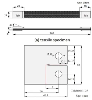
The twill-woven non-impregnated carbon fiber sheet was cut into squares (250 mm × 250 mm). Also, SiC powder was mixed in ethanol and uniformly dispersed for 30 minutes using an ultrasonic disperser. The SiC suspension was uni- formly mixed and stirred until a content of 1 wt.% was reached. The non-impregnated carbon fiber were laminated to 5 layers to form a composite reinforced with SiC powder under the vacuum infusion process (VIP). For comparison, a non-impregnated carbon fiber composite without SiC powder was also used. The final thickness of both composites was about 1.25 mm. By using a carbon fiber composite, a compact- tension specimen was made for fracture testing according to ASTM E 399 [10]. The initial notch was cut with a width (W) of 0.3 mm using an automatic fine-specimen cutter (Heiwa Technica). The initial ratio of the crack length (a) to width of the specimen is 0.5.
The shape and dimensions of the compact-tension speci- men used for fracture tests and the tensile specimen are shown in Fig. 1. The tensile specimen was manufactured according to ASTM D 3039 [11]. An aluminum tab (thickness: 2.0 mm) was attached to prevent damage and slippage from the holder during tensile testing. Also, as shown in Fig. 2, three types of tensile specimen were manufactured for acoustic emission
analysis: vinyl ester resin only, resin with SiC powder, and resin with a single carbon fiber. The curing time was about two days. The cured specimens were cut using a diamond- wheel fine cutter. These all specimens were made using the Table 1. Mechanical properties of SiC (particle size: 1 μm)
Material
Elastic modulus
(GPa)
Specific gravity (g cm-2)
Knoop hardness (kg mm-2)
Poisson’s ratio
GC1000 410 3.2 500 0.14
Table 2. Mechanical properties of vinyl ester Tensile
strength (MPa)
Elastic modulus
(GPa)
Elongation (%)
Heat strain temperature
(°C)
79 3.66 5.0 108
Table 3.Physical properties of the twill woven non-impregnated carbon fiber sheet for acoustic emission analysis
Material
Density
(counts cm-2) Thickness (mm)
Weight (g m-2)
Warp Fill
C520-3K 1.94 2.10 0.25 204
Fig. 1.Configurations for the tensile specimen (a) and compact- tension specimen (b) of the twill-woven carbon fiber composites with and without SiC powder
Fig. 2.Tensile specimens for acoustic emission analysis: (a) vinyl ester resin only, (b) resin and SiC powder, and (c) resin and a single carbon fiber
Fig. 3.Schematic diagram of the vacuum infusion process(VIP) method
VIP method, which is depicted in Fig. 3. Before connecting the resin hose to the inlet, the curing agent (1 wt.%) and accel- erator (1 wt.%) were stirred for 5 minutes to cure the vinyl ester resin. The resin was injected into the molding plates under vacuum.
2.2 Experimental Method
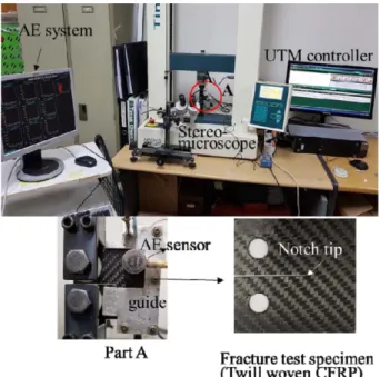
A tensile tester (Tinus-Olsen, H50KS) was used to inves- tigate the mechanical properties of the twill-woven carbon fiber composite with and without SiC powder. The experi- mental set-up system is shown in Fig. 4. The different twill- woven carbon fiber composite specimens tested are listed in Table 4 (the presence and absence of SiC is denoted by ‘I’ and
‘O’, respectively). Also TCFP and CCFP mean a tensile and CT specimen for carbon fiber composite.
Biaxial strain gauges were attached to the tensile specimens and experiments were performed with displacement control of 0.2 mm min-1. For the fracture tests, a thin compact-tension specimen with a thickness of 1.25 mm was used. A buckling prevention jig was attached to the specimen to prevent buck- ling during the fracture tests. The crack length was measured using a stereo-microscope (Nippon Optical Works Co.) at constant displacement and the data were transferred to a per- sonal computer via a digital converter (IT-005D, Mitzutoyo
Co.). Acoustic emission analysis was carried out with MIS- TRAS software and an AEDSP32-AE system (PAC Co.). The acoustic emission system detects elastic waves generated as a result of mechanical changes in the materials. Therefore, it is possible to observe crack initiation and propagation in real time. A R15 sensor with a resonant frequency of 150 kHz and a pico-sensor with a resonant frequency 750 kHz were used.
The threshold value was set at 44 dB using the Hsu-Nielsen method [12] to remove electrical and mechanical noise.
3. RESULTS AND DISCUSSION
3.1 Mechanical Properties
The load-displacement relationship during tensile testing is shown in Fig. 5. The relationship was linear until the specimen fractured suddenly. This behavior was the same with and with- out the SiC powder. The tensile test was carried out just two times because of the similarity of both results. The elastic modulus was almost same and the ultimate strength was slightly different for the two times test. The ultimate strength was 505.4, 506.2 in the TCFPI and 479.8, 481.3 MPa in the TCFPO, respectively. We selected lower values in both case conservatively. The elastic modulus of the TCFPI specimen was also higher than that of the TCFPO specimen. The mechanical properties are shown in Table 5.
3.2 Fracture Behaviors
The crack propagation path observed during fracture tests of the twill-woven carbon fiber composites (CCFPO and CCFPI) are shown in Fig. 6.
Table 4. Types of carbon fiber composite tested
Type Test Reinforced SiC
TCFPI Tensile Yes
TCFPO Tensile No
CCFPI Fracture Yes
CCFPO Fracture No
Fig. 4. The experimental set-up system under a fracture test
Table 5. Mechanical properties of the TCFPI and TCFPO Specimen Ultimate strength
(MPa)
Elastic modulus (GPa)
Poisson’s ratio (ν)
TCFPI 505.4 65.9 0.092
TCFPO 479.8 53.1 0.118
Fig. 5. Load-displacement relationship of TCFPO and TCFPI
The initial microcracks generated from the notch tip, the position of which depends on whether the fiber bundles are located on the weft or warp. For all specimens, the horizontal notch was inserted at the same position. The crack initially grew in the direction of the fiber because of the lower growth resistance. The crack continued to grow in a zigzag pattern in the first warp fiber bundle, which was orientated perpendic- ular to the notch direction. This zigzag shape means that the crack growth resistance was large in the direction of the warp fiber, and that fracture occurred in the both the fiber and the matrix. In addition, zigzag cracking occurred in the second warp fiber and the last crack propagated during the final stages.
In Fig. 7, the relationships are shown between the load, dis- placement for compact-tension specimens under the fracture test. The load variation for a displacement was initially linear and stably increased with non-linear behavior in both CCFPO and CCFPI. In the CCFPO specimen, non-linear behavior occurred after initial crack growth ④ and was kept until the maximum load. However, in the CCFPI specimen, the initial crack ① was occurred at just after the CCFPO case. Even though after initial crack growth, the load variation was kept the linear behavior until to show the non-linear behavior.
After the load reached a maximum value ②, ⑤ and then dropped rapidly. The load then fluctuated as like ③, ⑥ when
the zigzag crack continued to grow. For CCFPI, under a load of 358.3 N, the initial crack length was 0.49 mm and the dis- placement was 0.92 mm; the maximum load was 730 N. By contrast, for CCFPO, the initial crack length was 0.18 mm at a load of 313 N load, and the maximum load was 578 N. There- fore, the crack initiated with a smaller displacement and lower load for CCFPO than CCFPI even though the initial crack length is smaller. However, the load value of CCFPI after the rapid drop is higher than CCFPO and continued to the same load level without the entire fracture. This means that twill- woven carbon fiber reinforced with SiC powder have more stable crack growth resulting in an increase in the maximum load. In addition, the higher strength performance appears in the result of the CCFPI because that SiC powder contained in CCFPI were inhibiting the progress of the crack propagation.
3.3 Acoustic Emission Characteristics
The acoustic emission characteristics during tensile testing and specific frequency were related to the material properties.
In Fig. 8(a), a typical acoustic emission spectrum is shown for the fracture of the resin-only specimen. Two frequency bands of 100-228 kHz and 428-536 kHz are present. A typical acous- tic emission spectrum for the resin with SiC powder is shown in Fig. 8(b). In addition to the specific frequency bands of 100- 228 kHz and 428-536 kHz that were observed for the resin- only specimen, a new band at 232-424 kHz appeared that can Fig. 6. The crack propagation path acquired from fracture test
Fig. 7.Relationship between the load and displacement under fracture test for CCFPI and CCFPO
Fig. 8.Acoustic emission spectra measured during fracture for different specimens: (a) vinyl ester resin only, (b) resin and SiC powder, and (c) resin and carbon fiber
be attributed to the addition of SiC powder. In Fig. 8(c), the spectra for the specimen with resin and a single carbon fiber are shown. The frequency bands at 100-228 kHz and 428-536 kHz are the same as those for the fracture of the resin-only specimen. The additional frequency band of 576-864 kHz is therefore due to the failure of the fiber. A summary of these results is provided in Table 6.
3.4 Acoustic Emission Characteristics during Fracture The Acoustic emission spectra recorded during fracture by CT specimens are shown in Figs. 9-12 according to the crack extensions. The spectrum measured for crack initiation at the notch tip, which corresponds to point ①, ④ in Fig. 7, is shown in Fig. 9. In this case, the fiber was not broken, the crack initiated by the debonding of the resin and fiber, and spectrum reflects resin failure. The frequency bands were 100- 228 kHz and 428-536 kHz for CCFPO (Fig. 9(a)). For CCFPI, an additional frequency band of 232-424 kHz was observed (Fig. 9(b)), which is attributed to the SiC powder. The acoustic emission spectra recorded during crack propagation (corre- sponding to point ②, ⑤ in Fig. 7) are shown in Fig. 10. The frequency bands for resin failure in the presence and absence of SiC powder were the same as those observed in Fig. 9, although the amplitude of the emission was higher. For fiber breakage, a frequency band of 576-864 kHz was observed. The crack propagated along the horizontal fiber and fiber breakage occurred for the vertical fiber in the laminate layer.
In Fig. 11, the acoustic emission spectrum is shown for the crack advancing in a zigzag pattern, which corresponds to point ③, ⑥ in Fig. 7. For both CCFPO and CCFPI, the fre- quency bands were the same as those observed in Fig. 10, but with lower amplitude. The acoustic emission spectrum cor- responding to the final crack extension in Fig. 7 is shown in Fig. 12. The crack propagated along the horizontal fiber rap- idly and the amplitude of the acoustic emission was higher than in Fig. 11 because the fibers were broken to a large extent.
The frequency bands were the same as in Figs. 10 and 11.
Thus, the amplitudes and frequency ranges of acoustic emis- sions were very different between the CCFPO and CCFPI Table 6.Specific acoustic emission frequency ranges of the dif-
ferent material components
Type Frequency (kHz)
Resin only 100-228 Resin
428-536 Resin
Resin and SiC powder
100-228 Resin
232-424 SiC powder
428-536 Resin
Resin and carbon fiber
100-228 Resin
428-536 Resin
576-864 Fiber
Fig. 9.Acoustic emission spectra obtained for horizontal initiat- ing cracks in (a) CCFPO and (b) CCFPI
Fig. 10. Acoustic emission spectra obtained for large, horizontal growing cracks in (a) CCFPO and (b) CCFPI.
Fig. 11. Acoustic emission spectra obtained for a small, vertical crack in (a) CCFPO and (b) CCFPI
specimens. More complex spectra were obtained for CCFPI for each resin failure condition. This means that the crack advances in small increments in the specimen reinforced with SiC powder.
4. CONCLUSIONS
In this study, we evaluated the crack behavior of twill-woven CFRP composites with SiC powder using acoustic emission analysis. We found that SiC powder improved the strength and fracture characteristics of the twill-woven CFRP composite.
The main conclusions are summarized as follows. The crack advanced gradually in the CCFPI specimen reinforced with SiC powder, demonstrating that the added SiC powder enhanced the mechanical properties of the material. The acoustic emission frequency ranges at the point of breakage depended on the material; therefore, crack extension could be predicted on the basis of the frequency range of the acoustic emission. Finally, the fracture behavior was examinated on the basis of the specific frequency bands measured upon breakage.
This proposed method may be valuable as a safety evaluation method for crack extension and fracture behavior in various structures.
REFERENCES
1. Mahieux, C.A., “Cost Effective Manufacturing Process of Ther- moplastic Matrix Composites for the Traditional Industry: the Example of a Carbon-fiber Reinforced Thermoplastic Fly- wheel”, Composite Structure, Vol. 52, 2001, pp. 517-521.
2. Dlugosch, M., Lukaszenwicz. D., Fritsch, J., and Hiermaier, S.,
“Experimental Investigation of Hybrid Material Systems Con- sidering of Advanced Composites and Sheet Metal”, Composite Structures, Vol. 152, 2016, pp. 840-849.
3. Yoon, H.K., Kim. Y.K., and Park, J.S., “A Study on Fatigue Life of Al 7075/CFRP Multilayered Hybrid Composite Materials”, Journal of Ocean Engineering Technology, Vol. 10, No. 4, 1996, pp. 92-102.
4. Lee, J.K., Lee, J.H., and Yoon, J.H., “Evaluation of AE Charac- teristics on Microscopic Fracture Mechanism of Al 7075/
CFRP”, Composites Research, Vol. 15, No. 2, 2002, pp. 1-6.
5. Kwon, D.J., Wang, Z.J., Kim, J.J., Jang, K.W., and Park, J.M.
“Improvement of Mechanical and Interfacial Properties of Car- bon Fiber/epoxy Composites by Adding Nano SiC Fillers”, Adhesive International, Vol. 14, No. 2, 2013, pp. 75-81.
6. Johny, J.S., Venkatesan, K., Kuppan, P., and Ramanujam, R.,
“Hybrid Aluminium Metal Matrix Composites Reinforced with SiC and TiB2”, Proceeding Engineering, Vol. 97, 2014, p. 1018.
7. Kwon, O.H., and Yun, Y.S., “The Evaluation of Interlaminar Fracture Toughness and AE Characteristics in a Plain Woven CFRP Composites with DCB Specimen”, Journal of Korean Society of Safety, Vol. 20, No. 1, 2005, pp. 49-54.
8. Jose, M.J., Antolino, G., Elisabet, S., Francisco, J.J., and Angel, V., “Real-time Damage Mechanism Assessment in CFRP Sam- ples via Acoustic Emission Lamb Wave Modal Analysis”, Com- posites B, Vo. 36, 2015, pp. 317-326.
9. Fotouhi, M., Suwarta, P., Jalavand, M., Czel, G., and Wisnom, M.R., “Detection of Fiber Fractures and Ply Fragmentation in Thin-ply UD Carbon/glass Hybrid Laminates Using Acoustic Emission”, Composites A, Vol. 86, 2016, pp. 66-76.
10. E 399, “Standard Test Method for Plane Strain Fracture Tough- ness of Metallic Materials”, ASTM, Philadelphia, 1997.
11. D 3039, “Standard Test Method for Tensile Properties of Poly- mer Matrix Composite Materials”, ASTM, Philadelphia, 2006.
12. Matsuo, T., and Cho, H., “Development of AE Monitoring Sys- tem with Noise Reduction Function by Spectral Subtraction”, Materials Transactions, Vol. 53, No .2, 2012, pp. 342-348.
Fig. 12. Acoustic emission spectra obtained for a large, vertical crack in (a) CCFPO and (b) CCFPI