http://dx.doi.org/10.5369/JSST.2013.22.6.387 pISSN 1225-5475/eISSN 2093-7563
1. INTRODUCTION
Three dimensional (3D) video is becoming popular again. Between 1952 and 1954 more than 65 3D movies were produced by Hollywood before other cinema formats took over [1]. Recently the number of 3D video productions has started increasing, however the impractical process of 3D production remains a challenge.
To make 3D video using the stereoscopic method, two cameras are used. They should be attached to one holder, widely known as a 3D camera rig to get the correct pictures which have the same height and size to reduce picture distortion.
There are three types of 3D camera rigs. The first type is a manual rig. This needs full human control to adjust the cameras positions. The second is a motorized camera rig.
This still needs human control to operate through a human interface panel. This type has a higher cost since it contains a microprocessor for calculation and driving the positioning motors. The last is an automatic camera rig.
This type can reduce human dependence because it can
automatically move the cameras to the desired positions.
The system structure of this type of camera rig is obviously more complex and costly. Several parameters which are needed for determining the camera position are usually acquired from some kind of information devices or sensors attached to the camera rig.
Efforts are needed to simplify the 3D shooting operation in camera rigs. Several researchers have proposed their own methods. Liu et al proposed motorized zoom lenses for reconstructing Stereoscopic 3D (S3D) shooting with a two digital image sensors [2]. Heinzle et al proposed a computational camera system for their automatic camera rig by embedding image processing capability inside [3].
In this study, an automatic camera rig is developed using a low-cost laser sensor for capturing several distance parameters to reduce the operation time required.
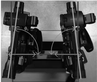
2. AUTOMATIC 3D CAMERA RIG SYSTEM As seen in Fig. 1 and Fig. 2, the camera rig system can be divided mainly into two movement parts. The horizontal movement part is for adjusting the distance between the two cameras on the rig. The distance between the two cameras is known as the interaxial distance (T). The cameras are moved simultaneously to the desired interaxial distance. The convergence movement part is for adjusting the convergence angle (θ
3) of the two cameras. They are
Capturing Distance Parameters Using a Laser Sensor in a Stereoscopic 3D Camera Rig System
Wan-Young Chung, Julian Ilham, and Jong-Jin Kim
+Abstract
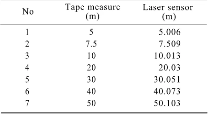
Camera rigs for shooting 3D video are classified as manual, motorized, or fully automatic. Even in an automatic camera rig, the process of Stereoscopic 3D (S3D) video capture is very complex and time-consuming. One of the key time-consuming operations is capturing the distance parameters, which are near distance, far distance, and convergence distance. Traditionally these distances are measured by tape measure or triangular indirect measurement methods. These two methods consume a long time for every scene in shot. In our study, a compact laser distance sensing system with long range distance sensitivity is developed. The system is small enough to be installed on top of a camera and the measuring accuracy is within 2% even at a range of 50 m. The shooting time of an automatic camera rig equipped with the laser distance sensing system can be reduced significantly to less than a minute.
Keywords : Automatic camera rig, Stereoscopic 3D (S3D), Distance parameters, Laser sensor
Department of Electronic Engineering, Pukyong National University, Nam-gu, Busan 608-737, Korea
+