DOI : 10.5369/JSST. 2011.20.1.8 pISSN 1225-5475/eISSN 2093-7563
Measurement of Brillouin Backscattering for Distributed Temperature Sensor Applications
Su-Hwan Kim1, Hyung-Woo Kwon1, Hyun-Ho Kwon2, Hang-Seok Jang2, Jee-Hyun Kim3,+and Shin-Won Kang3,+
Abstract
We present measurements of the Brillouin frequency shift in an optical fiber using a 1550 nm distributed feedback laser diode(DFB-LD) as a light source. By modulating the probe light with an electro-optic modulator, we confirm the stimulated Brillouin gain spectrum(BGS) and spontaneous BGS using the coherent detection method. We also confirm the applicability of the technique to distributed temperature sensors that measure the change in Brillouin frequency shift due to temperature variations.
Keywords : Temperature Sensor, Optical Fiber Sensor, Brillouin Scattering, Coherent Detection
1. INTRODUCTION
To measure physical quantities distributed over a wide range, a traditional multi-point measurement method exist that combines many electro-/mechanical point sensors.
However, this approach has several drawbacks including the requirement of a power-supply line and an information- transmission line for each sensor node. These limitations make installing sensors more complex and increase maintenance costs. Another approach, called the distributed measuring method, can overcome these limitations in many ways. Distributed measurements exploit the optical transport properties of fibers; namely, the fact the reflectance or absorption of light is influenced by the measurement target so the light intensity, frequency, and polarization state can change[1-3]. By measuring these changes, we can measure physical quantities in a specific point in the fiber. This method uses the entire optical fiber as a continuous sensor, so it is called the “distributed fiber sensor”[4]. Many studies have reported that, depending on the optical fiber length, it is possible to measure widely distributed physical quantities from hundreds of meters to
several kilometers using the distributed fiber sensor, and a distributed fiber sensor can replace traditional electro- /mechanical or information transmission type multi-point measurement systems.
The technique of optical time domain reflectometry (OTDR) technique which can measure physical quantities around optical fibers by measuring backscattered light through the optical fibers, is mainly used for distributed measurements. The OTDR technique using optical fiber sensors can obtain information on the distribution of physical quantities, such as the strain and temperature, from the measurement target, so it has been applied to fault diagnosis of optical communication lines and to monitor of structures[5,6]. Scattering in optical fibers can be characterized as either; elastic or inelastic scattering. In elastic scattering, the wavelength of the incident light is shifted, whereas in inelastic scattering, the wavelength is not shifted. Brillouin scattering is a type of inelastic scattering, so its frequency changes depending on the strain and temperature that is applied to the optical fiber[7-9].
In this stduy, to develop a Brillouin scattering optical fiber sensor system, we measured spontaneous and stimulated Brillouin backscattering and the Brillouin frequency shift as a function of temperature. We modulated probe light with an electro-optic modulator(EOM) to measure stimulated BGS and used a coherent detection method to measure spontaneous BGS. Finally, we confirm the applicability of the technique to the distributed temperature sensing by measuring the variation in the Brillouin frequency shift as a function of temperature.
1School of Electrical Engineering and Computer Science, Kyungpook National Unversity 1370 Sankyuk-dong, Buk-gu, Daegu 702-701, Korea
2Mine Reclamation Corporation,
30 Chungjindonggil 30, Jongro-gu, Seoul, 110-727, Korea
3 School of Electrical Engineering, College of IT engineering, Kyungpook National Unversity
+Corresponding author : [email protected], [email protected] (Received : Apr. 30. 2010 , Revised : Nov. 15, Dec. 14. 2010 ,
Accepted : Dec. 15. 2010)
2. THEORY
Brillouin scattering is based on Bragg-type diffraction propagating through the optical fiber. Due to an acoustic- wave effect, it modifies the refractive index by electro- striction which is akin to forming a reflection grating in the optical fiber. Brillouin scattering is thermally generated by the acoustic wave and at low incident light-levels, but as the incident light power increases, the incident wave interferes with the backscattered optical wave and a standing wave is generated in a self-stimulated phenomenon[10,11].
The acoustic wave propagates back and forth in the fiber, but the backscattered wave is Doppler shifted above and below the incident frequency. The incident wave and the Doppler-shifted scattered wave are combined to generate the diffraction grating, which propagates back and forth with the acoustic velocity. The incident waves is stable, backward-propagating wave generates the anti-Stokes signal and forward-propagating wave generates the Stokes signal. This feature is called stimulated Brillouin scatter- ing(SBS)[10,11].
In this process, the energy and momentum are conserved, so the wave vectors and frequencies of the three waves obey the relationships.
where, ωp and ωs refer to the frequencies of pump(incident) and Stokes wave, and kpand ksrefer to the corresponding wave vectors, respectively. From the dispersion relationship, the frequency ΩBand acoustic wave vector kAsatisfy the expressions
where, θis the angle between the pump and Stokes field, and the relationship |kp| |ks| is from Eq. (1)[12]. Eq. (2) shows that the frequency shift of the Stokes wave depends on the scattering angle. In particular, ΩBis maximum for backward scattering θ=πand disappears in the forward direction θ=0. For a single-mode optical fiber, only two cases are possible, as mentioned above. For this reason, SBS can occur in the backward direction, and the Brillouin shift can be expressed as :
In eq. (3), the relationship |kp|=2πnp/λpis used and np refers to the effective mode index at the pump wavelength, λp. When we apply values for general silica optical fiber to eq. (3), υA= 5.96 km/s and np= 1.45, νB 11.1 GHz when pumping at λp= 1.55 μm. This Brillouin frequency shift reacts strongly to temperature variations and relatively weakly to variations in strain[13]. The Brillouin frequency shift corresponding to a strain change of 300 μεis equal to that for a temperature change of 1 °C at about 1 MHz.
Using these characteristics, we can measure distributed temperature and strain along an optical fiber.
3. EXPERIMENTAL SETUP AND RESULTS 3.1 Measurement of SBS using an EOM
To apply Brillouin scattering to the distributed optical fiber sensor, it is essential to measure of the Brillouin gain spectrum(BGS) of the optical fiber. The Brillouin Frequency Shift(BFS) and BGS line widths depend on the material composition and the optical fiber structure, so an exact measurement of BGS is necessary with the optical fiber that is to serve as the sensor.
The distributed measurement of strain and temperature accompanies the change of the acoustic wave and the frequency, and uses Brillouin backscattering to analyze the inelastic interaction of optical waves. The technique is a time-domain measurement technique. The Brillouin optical time-domain analyzer(BOTDA), which uses the amplification phenomenon from SBS, is a sensor system
that measures external physical quantities experienced by optical fibers by using the interaction between the incident pump light and the probe light of the continuous wave(CW). The pulse and CW light are incident from both sides of the optical fiber. In this case, if νpis the frequency
Ω
B=ω
p-ω
s,k
A=k
p-k
s (1)Ω=|kA|νA=2νA|kp|sin( )
(2)ν B= =2npν A/λ p
(3)θ
Ω
B2π
2
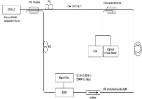
Fig. 1. Experimental setup to measure stimulated Brillouin scattering(SBS).
of pulse light and υcwis the that of the CW light, the frequency difference Δνbetween both light sources is Δ ν. If we adjust the frequency of the light sources to match the frequency difference and the BFS of the optical fiber, the optical power is converted from pulse light to CW light by SBS. In this case, CW light undergoes Brillouin amplification in the optical fiber, so we can analyze the Brillouin signal. We measured the amplified CW light signal using an optical spectrum analyzer(OSA) or an optical power meter. Fig. 1 shows the experimental setup for measuring BGS using SBS. The light source is a distributed feedback-laser diode(DFB-LD, Models COF915-508 and CQF938-R400, JDSU Co.Ltd) centered at 1550 nm.
Light from the DFB-LD entered the 2×2 coupler, and was split between two fibers to serve as pump and probe light. We applied an RF signal to the EOM by using a 26- GHz RF-signal generator and observed spectra changes in the probe light with the OSA. The modulation frequency was varied from 10.78 to 10.88 GHz in 500 kHz steps.
When the BFS of the optical fiber is the same as the modulation frequency, optical power is transferred from pump light to probe light, and we observe the amplification of the probe light.
To measure the BGS of used optical fiber, we measured the ratio of both side-bands upon varying the modulation frequency with the RF signal generator, as depicted in Fig.
3. We measure the maximum optical power ratio of the side-bands to be 0.5 dB for the 50 m optical fiber.
However, for the 8 km fiber, the maximum optical power ratio exceeds 40 dB. In the following result, the difference in amplification gain originates from the difference in interaction length between the pump light and the probe light, and because changes in the DFB-LD bias current causes the changes in the center frequency.
3.2 Measuring of spontaneous Brillouin scattering by using coherent detection
We configured loop type optics to amplify the probe light by SBS. With this method, the amplified signal is detected at the light receiver with optics configured for BOTDA system, so the dynamic range is large. This allows a reduction in signal-to-noise with equivalent computation time, leading to a reduction in data-acquisition time.
However, the fiber under test(FUT) and the system must be designed in the form of the loop-type optics. Unlike BOTDA, Brillouin optical time-domain reflecto- metry(BOTDR) using spontaneous Brillouin scattering
Fig. 2. Modulation spectrum of the probe light when modulation frequency is the same as the BFS(10.87 GHz).
Fig. 3. The Brillouin gain spectra of (a) 100 m (b) 8 km optical fiber.
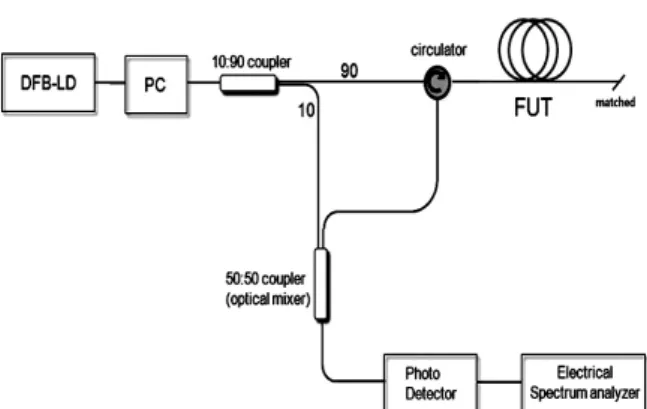
Fig. 4. Schematic of system for measuring spontaneous Brillouin backscattering by using the coherent detection.
(a)
(b)
requires a single-ended measurement system, so it has an advantage in terms of deployment but requires a sophisticated measurement method to detect weak signals, such as coherent detection.
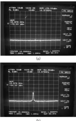
We designed the single-ended experimental optics setup for the BOTDR system as shown in Fig. 4, connected the FUT and performed experiments using coherent detection of spontaneous Brillouin backscattering. As photodetector, we used Agilent 83440C lightwave detector, which has a full-width-half-maximum(FWHM) of 20 GHz. As shown in Fig. 5, when the CW laser enters the circulator, spontaneous Brillouin scattering of the incident light occurs in the FUT, it returns to the system, then passed through the circulator, and is split by a 50:50 coupler. A fraction of 10 % of the split beam is directed to the other side of the coupler and the two beams are mixed in the coupler. At this point, the 50:50 coupler serves as an optical mixer; the sum and difference frequencies between the two beams are transmitted to the photodetector. The sum frequency cannot be detected because it exceeds the photodetector bandwidth. The difference frequency, and the BFS are displayed by the electrical spectrum analyzer(ESA). Fig. 5 shows measurement results with and without the FUT connected. When the FUT is connected, spontaneous Brillouin scattering occurs, which allows us to confirm the BFS of 10.978 GHz.
3.3 Measuring BFS variation as a function of temperature change
We used the same system as described Fig. 1 for measuring SBS to measure the BFS variation as a function of temperature. The modulation frequency was fixed at the BGS peak, and we measured its change with temperature.
The external temperature of a chamber was 25 °C, and a 2.5 km fiber was wound about a bobbin and placed into a vacuum oven. The temperature was increaseed at 15 °C intervals. We find that the Brillouin frequency changes linearly with temperature in the range studied. By fitting the data to a straight line, we can obtain a temperature coefficient of 1 MHz/°C which agrees with the theoretical value.
4. CONCLUSION
In this study, we configured loop-type optics and used a DFB-LD modulated by an EOM to generate the probe light to measure SBS in an optical fiber. By varying the modulation frequency and measuring the optical power ratio of both side-bands, we confirm the BGS of used optical fiber and detect the BFS value. In addition, by measuring spontaneous Brillouin backscattering using coherent detection, we observe a Brillouin frequency shift
Fig. 6. BGS variation due to temperature change.
Fig. 7. Brillouin frequency shift due to temperature change.
Fig. 5. Brillouin frequency shift by coherent detection (a) without the FUT and (b) with FUT.
(a)
(b)
of about 10.98 GHz in both experiments. The same system used to measure SBS, was used to measure BGS variations in the optical fiber due to temperature change. By tracing BFS, we confirm a temperature coefficient of about 1 MHz/°C.
The optical system used for this study consisted of a standard setup that used the basic principles of BOTDA or BOTDR, and we verified its applicability to a distributed temperature measurement system. We used only a CW light source, but distributed temperature measurements can be accomplished with our system using a pulsed light source as well. Furthemore, a novel distributed temperature measurement system can be achieved by applying an erbium-doped fiber amplifier(EDFA) to recover the power lost because of the pulsed light source, a laser-diode controller for controlling the DFB-LD which is sensitive to temperature and driving current and data acquisition system to the our configuration.
ACKNOWLWEDGMENTS
This study was supported by the Korean Mine Reclamation Corporation(MIRECO) through development of BOTDR system for distributed optical fiber measurement system.
REFERENCES
[1] Kyung-jin Lee, Jae-hee Park, and Shin-won Kang,
“The measurement of the internal strain of concrete specimen using optical fiber interferometric sensors”, Journal of Korean Sensors Society, vol. 10, no. 6, pp.
32-37, 2001.
[2] J. Smith, A. Brown, M. DeMerchant, and X. Bao,
“Simultaneous distributed strain and temperature measurement”, Appl. Opt., vol. 38, pp. 5372-5377, 1997.
[3] M. N. Alahbabi, Y. T. Cho, and T. P. Newson, “100 km distributed temperature sensor based on coherent detection of spontaneous Brillouin backscatter”, Meas.
Sci. Technol., vol. 15, pp. 1544-1547, 2004.
[4] Se-jong Baik, Il-bum Kwon, Chul Chung, and Jae- wang Yu, “Development of intrusion detection technique using fiber optic ROTDR sensor”, Journal of Korean Sensors Society, vol. 11, no. 4, pp. 19-27, 2002.
[5] Il-bum Kwon, Chi-yeop Kim, Man-yong Choi, and Jea- wang Yu, “Development of fiber optic BOTDA sensor for intrusion detection”, Journal of Korean Sensors Scociety, vol. 10, no. 3, pp. 16-25, 2001.
[6] K.T.V. Grattan and Dr. T. Sun, “Fiber optic sensor technology: an overview”, Sensors and Actuators, vol.
82, no. 1, pp. 40-61, 2000.
[7] D. Inaudi and B. Glisic, “Integration of distributed strain and temperature sensors in composite coiled tubing", SPIE, Smart Structures and Materials Conference, San Diego, USA, 2006.
[8] T. Kurashima and M. Tateda, “Thermal effects on the Brillouin frequency shift in jacketed optical silica fibers”, Appl. Optics, vol. 29, no. 15, pp. 2219-2222, 1990.
[9] V. leocoeuche, D. J. Webb, C. N. Pannell, and D. A.
Jackson, “Transient response in high-resolution Brillouin-based distributed sensing using probe pulse shorter than the acoustic relaxation time”, Opt. Lett., vol. 25, no. 3, pp. 156-158, 2000.
[10] R. W. Boyd, Nonliner optics 2nd ed., Academic Press, San Diego, Chap. 9, 2003.
[11] Y. R. Shen, The principles of nonlinear optics, Wiley, New York, Chap. 11, 1984.
[12] C. L. Tang, “Saturation and spectral characteristics of the stokes emission in the stimulated brillouin process”, J. Appl. Phys., vol. 37, pp. 2945-2955, 1966.
[13] P. C. Wait and T. P. Newson, “Landau-Placzek ratio applied to distributed fiber sensing”, Optics communication, vol. 122, no. 6, pp. 141-146, 1996.
Jee-Hyun Kim
received the Ph.D.degree in bio-medical engineering, from University of Texas at Austin in 2004. He is a professor in the School of Electrical Engi-neering, college of IT engi-neering of Kyung-pook Natio- nal University.
He is a member of The Optical Society of Korea and IEEE. His current research interests optical coherent tomography, Brillouin optical time domain reflectometry and multi photon micro-scopy.
Shin-Won Kang
received the Ph.D.degree in bio-medical science, from the University of Keio in 1993. He is a professor in the School of Electrical Engineering, college of IT engineering of Kyungpook National University. He has founded DTEC (Display Tech- nology Educational Center) in the campus, as a Chief of the Center, from 2003 up to now. His current research interests include opto electronic fun- ctional device, Organic Light Emitting Diode and Nano-rod device.
Hyun-Ho Kwon
received the master course degree in mineral and energy resources Hyun-Ho Kwon received the master course degree in mineral and energy resources engineer energy mineral resources management. And He takes charge of director of institute of mine reclamation corporation.Hang-Seok Jang
received the B.S.degree in geosystem engineering from Hanyang University of South Korea.
He is currently working toward the master course degree in rock mechanics at Seoul National University. And He is a associate researcher of institute of mine reclamation technology of mine reclamation corporation. He is now performing reaseach on application of BOTDR system to mine subsidence monitoring.
Su-Hwan Kim
received the M.S.degree in electrical engineering and computer science from Kyungpook National University, South Korea. He is currently working toward the Ph.D degree in Prof. Kang's group at Kyungpook National University, Daegu. His current research is focused on the study of distributed fiber sensor and multi-photon microscopy.
Hyung-Woo Kwon
received the B.S. and M.S. degree in electrical engineering from the Kyungpook National University, Daegu, South Korea, Hyung-Woo Kwon received the B.S. and M.S. degree in electrical engineering from the Kyungpook National University, Daegu, South Korea, degree under Prof. Jae-Won Song at Kyungpook National Univ.His current research is focused on the study of optical time domain reflectometry.