• 검색 결과가 없습니다.

Preparation of a Semi-Conductive Thin Film Sensor for Measuring Occlusal Force

N/A
N/A
Protected

Academic year: 2021

Share "Preparation of a Semi-Conductive Thin Film Sensor for Measuring Occlusal Force"

Copied!
5
0
0

로드 중.... (전체 텍스트 보기)

전체 글

(1)

http://dx.doi.org/10.5369/JSST.2015.24.2.88 pISSN 1225-5475/eISSN 2093-7563

Preparation of a Semi-Conductive Thin Film Sensor for Measuring Occlusal Force

Siwon Yu, Nari Kim and Youngjin Lee

+

Abstract

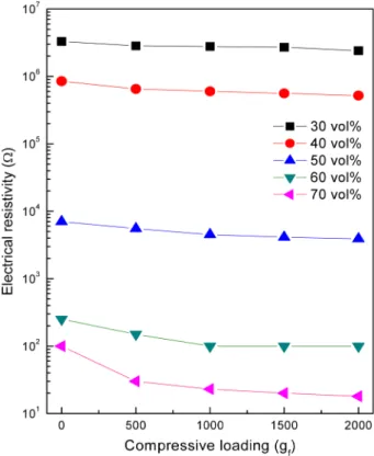
In order to study the semi-conductive characteristics of carbon black-filled ethylene–propylene–diene monomer (EPDM) composite film, which is used for measuring occlusal force, composite samples with volume ratios of carbon black to EPDM ranging from 30%

to 70% were prepared. The process of making a composite film consists of two steps, which involve the preparation of a slurry com- position and the fabrication of a thin film using solution casting and a lamination process. To prepare the slurry composition, we dis- persed carbon black nanoparticles into an organic solvent before mixing with an EPDM solution in toluene. The mechanical and electrical properties of the resulting carbon black-filled EPDM film were then investigated, and the results showed that the electrical resistance of a film decreases with the increase in the carbon black content. Furthermore, improved elastic recovery was observed after cross-linking the EPDM.

Keywords: Carbon black, EPDM, Solution process, Electrical resistance, Elastic recovery

1. INTRODUCTION

In recent years, much research has been devoted to the measurement of occlusal force and a wide range of methods for the determination of occlusal forces have been developed. In a dental context, occlusion usually refers to contact between the upper and lower teeth when the mouth is closed, as occurs during chewing or at rest [1].

Occlusion measurements are essential in prescribing and fitting many types of dental appliances such as false teeth and orthodontic devices. Up until now, however, no device has been developed for effectively and economically measuring dental occlusal force. Currently, the most commonly used devices are occlusion foil, articulating paper, and wax occlusal rims, which are inexpensive and easy to use but provide limited information.

Other methods, such as X-raying and dental casting for bite, are expensive, time consuming, and not suitable for large-scale use in dental offices [1-3].

Recently, a number of force sensing resistors based on

conductive polymer films have been introduced. Such film sensors are simple and can enable quick force measurement.

One candidate method for occlusal force measurement is the use of a film sensor that measures pressure-dependent electric resistance. Such devices disturb dental occlusion to a lesser degree and can provide detailed information on the interaction of dental surfaces. Additionally, film sensors can be fabricated very inexpensively and used repeatedly [4-5].

In this study, a semi-conductive thin composite film sensor for measuring occlusal force was fabricated. The thinness and flexibility of this film sensor allows occlusion to be accurately measured. We studied the sensing characteristics of fabricated films and evaluated the possible usefulness of such film sensors in the assessment of occlusal forces.

2. EXPERIMENTAL

2.1 Materials

All of the materials in this study were commercial products that could be used as they were received without further treatment.

The carbon black — an electro-conductive carbon black (ketjen black, EC-300J) in granular form — was supplied by David Tech Co., Ltd., Korea. This carbon black has a primary particle size of 40 nm and an apparent bulk density of 135 kg/m

3

. The ethylene–

propylene–diene monomer (EPDM) rubber was obtained from Chemseoul Co., Korea. EPDM can be cross-linked with peroxides Electronic Materials & Module Team, Korea Institute of Ceramic Engineering

& Technology, 101, Soho-ro, Jinju-si, Gyeongsangnam-do, Korea

+

Corresponding author: [email protected]

(Received : Feb. 24, 2015, Revised : Mar. 24, 2015, Accepted : Mar. 25, 2015)

This is an Open Access article distributed under the terms of the Creative Commons Attribution Non-Commercial License(http://creativecommons.org/

licenses/bync/3.0) which permits unrestricted non-commercial use, distribution,

and reproduction in any medium, provided the original work is properly cited.

(2)

in order to make it highly resistant to oxygen, ozone, UV light, and heat. Toluene (99.5%), which was used as an organic solvent, was purchased from Daejung Chemical Co., Korea. The cross- linking agent, dicumyl peroxide (DCP, 97%), was purchased from Aldrich Co., U.S.A. and used as received. A dispersing agent, BYK111, was obtained from Altana Co., Germany and used for stable dispersion of the carbon black.

2.2 Preparation of the composite film

2.2.1 Ultrasonication treatment

Ultrasonic treatment was performed in order to crush aggregated carbon black and disperse it into the toluene.

Ultrasonication was conducted for 3 h at 22% of the vibration amplitude. During ultrasonic treatment, on/off pulses of 20/20 s duration were used to minimize the increase in temperature.

2.2.2 Preparation of carbon black/EPDM slurry First, the polymer solution was prepared by dissolving EPDM in toluene for 12 h at 120

o

C. The resulting polymer solution was mixed with carbon black/toluene and then the cross-linking and dispersing agents were added to the solution. Following complete dissolution and dispersion, the resulting carbon black/EPDM slurries were defoamed in vacuum in order to remove air bubbles before being subjected to aging treatment for 3 h. Table 1 lists the carbon black/EPDM slurries prepared with various amounts of carbon black used in this study.

2.2.3 Fabrication of thin film

The carbon black/EPDM thin films were fabricated using a solution casting process in which casting was performed on a carrier film using a blade with gap height 400 μm at a constant casting speed of 1.5 m/min. After casting, the films were dried at an air flow temperature of 65

o

C and the thin films were then cut into small 5 cm × 5 cm pieces, two or three of which were laminated at 100

o

C at 50 bar of pressure for 30 s. The thicknesses

of the resulting films were measured to be 100 – 400 μm [6].

2.2.4 Curing treatment

To make cross-links in the EPDM, a curing treatment using peroxide was carried out in a vacuum-dry oven at 160

o

C for 1 h.

The resulting polymers had a higher crosslink density.

2.3 Characterization

The electric sensing properties of carbon black-filled EPDM film were assessed through electric resistivity measurement using a load cell and a digital multi-meter. Both sides of the film were covered with copper plate as a conducting layer. A compressive load was then applied to the top surface of the layered plate through compression or the use of a tensile load cell. The change in electrical resistance of the plate with increasing loading force was measured using a digital multi-meter.

3. RESULTS AND DISCUSSIONS

3.1 Scanning electron micrograph

Figs. 1(a) and (b) show plane and cross-sectional scanning electron microscope (SEM) images of the film, which has a rough, less-dense fracture cross-section and a thickness of about 300±10

Table 1. Compositions of carbon black/EPDM slurries.

Carbon black : EPDM (vol%)

3:7 4:6 5:5 6:4 7:3

carbon black 1.7 g 2.7 g 4.0 g 6.0 g 9.3 g EPDM 40.0 g 40.0 g 40.0 g 40.0 g 40.0 g BYK111 1.5 g 1.5 g 1.5 g 1.5 g 1.5 g

DCP 0.05 g 0.05 g 0.05 g 0.05 g 0.05 g

toluene 500 g 500 g 500 g 500 g 500 g

Fig. 1. SEM images of carbon black-filled EPDM composite film:

(a) plane view of SEM image; (b) cross-sectional SEM

image; (c) surface of non-cross-linked film, and; (d) surface

of cross-linked film.

(3)

μm. Based on our observations, we postulate that the film was uniformly fabricated at micro-level thickness. Figs. 1(c) and (d) show the effects of crosslinking on the surface of the film. It is seen from the figure that the roughness of the cross-linked film surface is greater, which indicates that, although crosslinking did not significantly alter the film thickness, it increased surface roughness, modified the topography, and greatly increased the film stiffness.

3.2 Effect of carbon black content on electric resistance Fig. 2 shows the results of increasing carbon black content on electric resistance, as assessed by performing resistivity measurement on film samples with carbon black content ranging from 30 to 70 vol% under 2,000 g

f

of loading force. The results show the electrical resistivity displaying a logarithmic decrease with increasing carbon black content; the resistance starts to fall sharply at 40 vol% carbon black, reaching about 20 Ω at the maximum loading of 70 vol%. This behavior might be explainable through percolation theory, as conductive behavior near the percolation threshold shows dramatic changes corresponding to the dielectric and electric properties at the threshold [7]. Judging from the percolation curve in [7], the critical level of carbon black content would be expected to be at about 40–50 vol%.

3.3 Effect of loading force on electric resistance Fig. 3 shows the electric resistance change in a film with increasing compressive load. Varying load forces ranging from

500–2,000 g

f

were applied to the top surface of the film, with the results showing an initially moderate decrease in electrical resistivity with increasing compressive load that becomes even less pronounced as the load continues to increase. This result demonstrates that there is a relation between the applied compressive strength and the electrical resistance of a film, an experimental phenomenon that can be explained as follows. As the compressive load is increased, the volume of the composite film decreases gradually. This reduces the distance between loaded carbon black particles, bringing more of them into contact and thereby lowering the electrical resistivity of the film [8].

3.4 Effect of film thickness on electric resistance Composite films with thickness ranging from 0.1 to 0.4 mm were prepared and tested for electric resistance. Fig. 4 shows the curves of change in resistivity with increasing load for the respective films; it is seen that, while the shapes of the curves are similar for all four cases, the electric resistance at a given compressive loading increases with the increase in the thickness.

This may be partly due to an increase in some mechanical property in the thickness direction of the composite film.

Alternatively, it is possible that increasing the thickness hinders Fig. 2. Change in electric resistance of a film with increasing carbon

black content under 2,000 g

f

compressive loading.

Fig. 3. Change in electric resistance of a film with increased com-

pressive loading.

(4)

conductive path formation in the thickness direction. Regardless, this result shows that thickness plays an important role in determining the electrical conductivity of a film [9].

3.5 Effect of cross-linking on elastic recovery To determine the effect of cross-linking on elastic recovery, the electric resistance was observed before and after compressive reloading. Elastic recovery is calculated using the following equation:

(1)

where Ω

0

is the initial electric resistance under loading-free conditions and Ω

0

' is the electric resistance under loading-free

conditions following compressive unloading.

The results shown in Fig. 5 suggest that cross-linked samples exhibit higher elastic recovery than non-cross-linked samples of all thicknesses. From this, it is apparent that improved elastic recovery will occur after curing treatment, as the crosslinking density of the EPDM polymer chains increases as a result of the curing process. The large crosslinks resulting from this process resist compression, which leads to higher impact resistance against external forces and better elastic recovery. Increasing film thickness, however, does not noticeably affect the elastic properties of the film; as seen in the figure, films ranging from 0.1 to 0.4 mm show almost identical elastic recovery characteristics.

This result indicates that the film undergoes no stiffening effect in the submicron thickness range [10].

4. CONCLUSIONS

In this study, we fabricated a semi-conductive thin composite film sensor for measuring occlusal force. The influence of parameters affecting the electric resistance, such as conductive particle content, compressive loading, and film thickness, was investigated, in addition to the effect of cross-linking on the elastic recovery of a film. The important results are summarized as follows.

(1) Electrical resistance significantly declined at 40 vol%

carbon black content, reaching about 20 Ω at 70 vol%.

(2) Increasing the compressive loading from 500 to 2,000 g

f

resulted in gradual reduction of the electrical resistance.

(3) It was found that several electrical and physical properties were dependent on film thickness.

(4) In particular, cross-linking in the EPDM led to improved elastic recovery of the film.

Overall, we demonstrated that the film developed in this study is suitable for dental occlusal force measurements and we can confidently say that it can be used to develop a sensor applicable to various dental applications. However, additional studies are definitely required for a more comprehensive understanding of the characteristic changes in different types of materials. Furthermore, additional work will be required to determine how to measure occlusal force more accurately.

REFERENCES

[1] C. P. Fernandes, P. J. Glantz, S. A. Svensson, and A. Berg- Elastic recovery % ( ) Ω′

0

Ω

0

--- 100 ×

=

Fig. 4. Change in electric resistance curve of a film with increasing film thickness.

Fig. 5. Change in elastic recovery following cross-linking treatment.

(5)

mark, “A novel sensor for bite force determinations”, Dent.

Mat., Vol. 19, No. 1, pp. 118-126, 2003.

[2] K. R. Lin, C. H. Chang, T. H. Liu, S. W. Lin, and C. H. Lin,

“Experimental and numerical estimations into the force dis- tribution on an occlusal surface utilizing a flexible force sensor array”, J. Biomech., Vol. 44, No. 1, pp. 1879-1884, 2011.

[3] F. S. Bastos, E. B. Las Casas, G. C. D. Godoy, and A. B.

Meireles, “Numerical analysis of human dental occlusal contact”, Mat. Sci. and Eng., Vol. 10, No. 1, pp. 1-9, 2010.

[4] K. Kohyama, E. Hatakeyama, T. Sasaki, H. Dan, T. Azuma, and K. Karita, “Effect of sample hardness on human chew- ing force : a model study using silicone rubber”, Arch. Oral Biol., Vol. 49, No. 1, pp. 805-816, 2004.

[5] K. Baba, Y. Tsukityama, and G. T. Clark, “Reliability, valid- ity, and utility of various occlusal measurement methods and techniques”, J. Prosthet. Dent., Vol. 83, No. 1, pp. 83- 89, 2010.

[6] E. Mercadelli, A. Sanson, P. Piansco, E. Roncari, and C.

Galassi, “Influence of carbon black on slurry compositions for tape cast porous piezoelectric ceramics”, Ceram. Int., Vol. 37, No. 1, pp. 2143-2149, 2011.

[7] W. Bauhofer, and J. Z. Kovacs, “A review and analysis of electrical percolation in carbon nanotube polymer com- posites”, Compos. Sci. Tech., Vol. 69, No. 1, pp. 1486-1498, 2009.

[8] P. Wang, T. Ding, “Conductivity and piezoresistivity of con- ductive carbon black filled polymer composite”, J. App.

Polym. Sci., Vol. 116, No. 1, pp. 2035-2039, 2010.

[9] Y. S. Kim, “Fabrication of carbon black-polymer composite sensors using a position-selective and thickness-controlled electrospray method”, Sens. Actuators B., Vol. 147, No. 1, pp. 137-144, 2010.

[10] C. F. Antunes, M. V. Duin, and A. V. Machado, “Effect of crosslinking on morphology and phase inversion of EPDM/

PP blends”, Mat. Chem. and Phys., Vol. 133, No. 1, pp.

410-418, 2012.

수치

Table 1. Compositions of carbon black/EPDM slurries.
Fig. 3. Change in electric resistance of a film with increased com- com-pressive loading.
Fig. 4. Change in electric resistance curve of a film with increasing film thickness.

참조

관련 문서

Resistance, Resistivity and Electric conductivity of OFHC Cu, 3DiGn-Cu composite, 3D-Graphene network, Cu powder.. Ratio of resistivity

Effect of planting date on growth and seed yield of Danfa black

25 Temperature Contour Maps on the MEMS-based Black Body Surface at Cold Case ((a) Heating Range, (b) Cooling Range) ··· 61 Fig.. 26 Temperature Profiles of MEMS-based Black

The limit is therefore the carbon char as a carrier utilizing only 27% of available hydrogen but sequestering 91kg of carbon dioxide (as measured experimentally) per million

Because a car black box device saves information about situations that occur while a car in question with the on-board black box travels to allow analysis of car accidents

“wye” as shown. Calculate the magnitude and direction of the force exerted on the “wye” by the gasoline.. What will be the horizontal component of force exerted by the water

Lee, “Effective Ag Doping by He-Ne Laser Exposure to Improve the Electrical and the Optical Properties of CdTe Thin Films for Heterostructured Thin Film

A retrospective analysis of invasive tumor percentages of GSS tumor samples showed that samples with high tumor content correlated well with FNAB samples