Vol. 25, No. 6, pp. 802-808, October 31, 2019, ISSN 1229-3431(Print) / ISSN 2287-3341(Online) https://doi.org/10.7837/kosomes.2019.25.6.802
1
* First Author : [email protected], 051-410-4873
†Corresponding Author : [email protected], 052-290-1610
Control Method for Performance Improvement of BLDC Motor used for Propulsion of Electric Propulsion Ship
Hyeonmin Jeon
*․Jaejung Hur
**․Kyoungkuk Yoon
***†* Department of Marine System Engineering, Korea Maritime and Ocean University, 727 Taejong-ro, Busan 41192, Korea
** Division of Education, Korea Institute of Maritime and Fisheries 367 Haeyang-ro, Busan 49111, Korea
*** Department of Electricity, Ulsan Campus of Korea Polytechnics, 155 Sanjeon-gil, Ulsal 44482, Korea
전기추진선박의 추진용으로 사용되는 브러시리스 직류전동기의 제 어방법에 따른 성능향상에 관한 연구
전현민
*․허재정
**․윤경국
***†* 한국해양대학교 대학원 기관시스템공학과, ** 한국해양수산연수원, *** 한국폴리텍대학 울산캠퍼스 전기과
Abstract : DC motors are used extensively on shipboard, including as the ship’s winch operating motor, owing to their simple speed control and excellent output torque characteristics. Moreover, they were used as propulsion motors in the early days of electric propulsion ships. However, mechanical rectifiers, such as brushes, used in DC motors have certain disadvantages. Hence, brushless DC (BLDC) motors are increasingly being used instead. While the electrical characteristics of both types of motors are similar, BLDC motors employ electronic rectifying devices, which use semiconductor elements, instead of mechanical rectifying devices. The inverter system for driving conventional BLDC motors uses a two-phase excitation method so that the waveform of the back electromotive force becomes trapezoidal. This causes harmonics and torque ripple in the phase current switching period in which the winding wire through which the current flows is changed. Researchers have studied and presented various methods to reduce the harmonics and torque ripple. This study applies a cascaded H-bridge multilevel inverter, which implements a proportional–integral speed current controller algorithm in the driving circuit of the BLDC motor for electric propulsion ships using a power analysis program. The simulation results of the modeled BLDC motor show that the driving method of the proposed BLDC motor improves the voltage waveform of the input side of the motor and remarkably reduces the harmonics and torque ripple compared with the conventional driving method.
Key Words :Electric Propulsion Ship, Brushless DC motor, Multilevel inverter, Total harmonics distortion, Torque ripple
요 약 : 직류전동기는 속도제어가 간단하고, 출력 토크특성이 우수한 장점으로 윈치나 카고 펌프 모터 등으로 선박에서 많이 사용되었 으며, 전기추진선박이 도입된 초기에는 선박용 추진전동기로도 적용되었다. 하지만 브러시와 정류기와 같은 기계적 정류장치의 단점으로 인해 최근에는 직류전동기와 전기적인 특성은 매우 유사하지만 기계적인 정류장치를 설치하지 않고 반도체 소자를 이용한 전자적인 정 류장치를 사용하는 브러시리스 직류전동기의 사용이 증가하고 있다. 기존의 브러시리스 직류전동기를 구동하기 위한 인버터 시스템은 2 상여자방식을 사용하므로 역기전력파형이 사다리꼴모양으로 되며, 이로인해 전류가 흐르는 권선이 바뀌는 상전류 전환 구간에서 고조파 와 토크리플이 발생하게 된다. 이러한 고조파와 토크리플을 저감하기 위한 다양한 방안이 연구되어 발표되었으며, 본 연구에서는 전력분 석프로그램을 이용하여 브러시리스 직류전동기의 구동회로에 비례적분 속도전류제어기 알고리즘을 구현한 Cascaded H-Bridge 멀티레벨 인버터를 적용하였다. 모델링한 브러시리스 직류전동기의 시뮬레이션을 통해 제안하는 전동기의 구동방식을 적용하는 경우에 기존의 구 동방식에 비해 전동기 입력측 전압파형 개선과 고조파 및 토크리플이 현저히 저감되는 결과를 확인할 수 있었다.
핵심용어 : 전기추진선박, 브러시리스 직류전동기, 멀티레벨 인버터, 총고조파왜형률, 토크리플
1. Introduction
Since the invention of DC motors in 1832, they have been used in various places on shipboard, such as winch operating motor etc. due to their simple speed control and excellent torque characteristics (Yoon, 2015). However, DC motors require a commutator and brush to generate torque in the same direction.
These mechanical rectifying devices eventually wear out due to continuous operation, thus requiring regular maintenance.
Moreover, not only is high-speed rotation difficult but also the motor generates electrical and mechanical noise due to the installed rectifying device (Salah et al., 2011). Therefore, brushless DC (BLDC) motors are increasingly being used in shipboard.
While the electrical characteristics of both types of motors are very similar, BLDC motors employ electronic rectifying devices, which use semiconductor elements, instead of mechanical rectifying devices (Dwivedi and Tiwari, 2013; Niapour et al., 2014).
BLDC motors are equipped with Hall sensors that can detect the permanent magnet position of the rotor to rotate it in a certain direction. Based on the position information of the rotor obtained from the Hall sensors, the device selects two phases to which the current should flow for continuous rotation, and the inverter, which is the driving circuit, is controlled to excite the armature winding. Conventional BLDC motors use 2-phase excitation to control the inverter. When these harmonics occur, they have large and small effects on all componenets of the overall system (Jeon et al., 2018). Due to the influence of harmonics flowing in generators or propulsion motor, iron loss and copper loss increase, which leads to an increase in the temperature of the device. In addition, the harmonics cause the skin effect and the proximity effect to occur in the wire, thereby increasing the heat loss emitted. As a result, the back EMF waveform becomes trapezoidal, causing harmonics and torque ripple in the phase current transition section, where the winding wire through which the current flows is changed (Cui et al., 2015). The methods proposed to reduce harmonics and torque ripple include installing an LC filter by low pass filtering circuit at the rear end of the inverter for driving the BLDC motor (Rajan and Vasantharathna, 2009), installing a front end integrated dual output dc-dc converter and power factor correction using isolated zeta converter (Amirthalingam and Mahadevan, 2017; Niasar et al., 2006; Rjeev et al., 2016). In addition, there is a method of sending the same average torque using a 5-pahse
BLDC motor using a 5-phase excitation method (Parsa and Toliyat, 2005).
2. Structure of BLDC motor
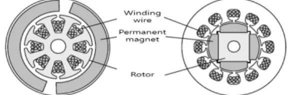
BLDC motors address the defects caused by the mechanical rectifiers of DC motors. For this purpose, the motor measures the position of the rotor through a sensor and replaces the functions of the rectifier and brush (mechanical rectifying devices) with semiconductor elements. As shown in Fig. 1, a field is created through a permanent magnet and positioned on the rotor, and the armature is placed on the stator to reverse the structure of the stator and rotor with the DC motor (Kim, 2016; Raja and Geethallakshmi, 2016).
Fig. 1. Comparison of DC motor and BLDC motor structures.
In addition, to apply power using an electronic rectifier instead of a mechanical rectifier (brush, commutator, etc.), the motor is equipped with a sensor for detecting the magnetic pole position of the permanent magnet of the rotor, as well as a motor driving circuit employing semiconductor elements, which use the signal of the sensor to change the winding wire through which the current flows. Table 1 compares the characteristics of BLDC motors with such a structure to DC motors.
No. Description
1
Unlike DC motors, BLDC motors are easy to manage, reliable, and have a long lifetime thanks to the lack of brush or rectifier.
2 High-speed operation
3
Has the excellent control characteristics of DC motors, as well as a high torque-to-weight ratio and small moment of inertia, making it suitable for servo motors.
4 The structure of the motor can be reduced in size.
5 Reduced noise due to lack of mechanical contact Table 1. Comparison of DC motor and BLDC motor strengths
It has many advantages like Table 1. However, BLDC motors are expensive because of permanent magnets, and there is a need for a hall sensor that detects the position of permanent magnets.
Due to the characteristics of BLDC motors, it has not been applied to large-sized electric propulsion ships. But the installation of electric propulsion systems using BLDC motors as propulsion motors has been increasing in small coastal ships and leisure boats.
3. Comparison of conventional driving method and BLDC motor driving method using the proposed cascaded H-Bridge multilevel inverter
3.1 Conventional BLDC Motor Driving Method
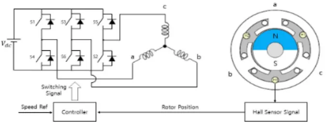
Fig. 2 shows the basic driving system of the BLDC motor.
The current flows according to the position of the permanent magnet to induce the rotor to rotate in a certain direction, and the stator winding wire that generates magnetic flux is changed to continuously generate force in the rotor. The position of the rotor must be known for this process, which can be determined through a Hall sensor (Kim, 2016; Niapour et al., 2014).
The Hall sensors are arranged at intervals of 120 degrees.
Based on the position information of the rotor obtained from the Hall sensors, the device selects two phases from among six sections to which the current should flow for continuous rotation, and the inverter, which is the driving circuit, induces excitation.
During BLDC motor driving, only two of the 3-phase winding wires are always excited, and the third is not excited. This driving method is called 2-phase excitation. In this case, each switching device is energized at 120-degree intervals (Salah et al., 2011).
Fig. 2. Diagram of conventional BLDC motor driving system.
As shown in Equation (1), in 2-phase excitation, the motor torque is equal to the magnitude of the excited 2-phase current,
excluding the phase current switching section. As the flow direction is reversed, it is expressed as the arithmetic product of the back-EMF magnitude and the current magnitude (Doss et al., 2013; Jeon et al., 2018).
(1)
Even if the back EMF is an ideal trapezoid, a ripple may exist in the current in the phase current switching period, thereby causing torque ripple. This torque ripple generates noise and vibration, reducing the speed control characteristics and causing higher harmonic content at low speeds. Therefore, researchers have investigated numerous methods to address this issue such as LC filter etc. (Prathibanandhi and Ramesh, 2018; Rajan and Vasantharathna, 2009). This paper proposes a method to reduce the harmonics and torque ripple by applying a cascaded H-bridge multilevel inverter to the driving circuit.
3.2 Motor Driving Method using the proposed cascaded H-Bridge multilevel inverter
The proposed multilevel inverter can generate at least a 3-level output voltage on the output side. Moreover, its output voltage waveform exhibits much higher harmonic reduction than conventional 2-level inverters. As shown in Fig. 3, the cascaded H-bridge multilevel inverter comprises single-phase full bridge inverters referred to as H-bridge cells. As shown in Table 2, one H-bridge cell generates three output voltages of
, 0 or
according to the switching state (Bin and Narimani, 2017).This inverter uses twice as many semiconductor switching elements as conventional 2-level inverters. If separate DC power supplies are required but the same capacity is implemented, the capacity of the semiconductor switching element is also reduced, as the size of the DC power supply is half that of a 2-level inverter.
Fig. 3. Diagram of H-Bridge cell.
S1 S2 S3 S4 Output Voltage
1 0 0 1
1 0 1 0 0
0 1 0 1 0
0 1 1 0
Table 2. Output Voltage According to Switching State of H-Bridge Cell
Furthermore, to obtain excellent speed control characteristics, as shown in Fig. 4, the cascaded H-bridge multilevel inverter for the driving circuit is used to control the torque and current, and a proportional integral controller, the BLDC motor controller, is used to control the current and motor speed. The output of the speed controller is given by the current command of the motor, and a current sensor is required to measure the actual current of the motor.
Fig. 4. Circuit diagram of BLDC motor driving method using the proposed cascaded H-Bridge multilevel inverter.
4. Modeling the BLDC Motor Driving System for Simulation
The control of BLDC motors that output current, magnetic flux, and counter electromotive force as a square wave directly uses the ABC coordinate system shown in Equations (2) - (4), rather than the coordinate axis conversion used in induction motors during vector control (Ji et al., 2018; Kim, 2016).
(2)
(3)
(4)
Fig. 5 shows a conventional BLDC driving inverter, a 2-level inverter with six IGBT elements. Fig. 6 shows a BLDC driving circuit using the proposed cascaded H-bridge multilevel inverter.
Fig. 5. Diagram of Conventional 2-Level Inverter.
Fig. 6. Diagram of Proposed Cascaded H-Bridge Multilevel Inverter.
Regarding the control of the driving circuit of the BLDC motor, as shown in Equation (1), the output torque of the motor is only affected by the magnitude of the phase current. Thus, for the control torque of the BLDC motor, the magnitude of the 3-phase current must be used. To control the phase current magnitude on the input side of the BLDC motor, the speed and current controller algorithm using the proportional integral controller in Fig. 7 is applied to the driving circuit. The speed controller outputs a DC current command as shown in Equation (5). Here,
and
are used to calculate the control bandwidth
based on the proportional gain and integral gain.
(5)
Fig. 7. Diagram of controller for speed and torque control of the proposed BLDC motor.
Furthermore, to generate the command voltage calculated by the controller, the unipolar PWM method is applied to the semiconductor element switching signaling method of the inverter.
While the unipolar PWM technique is more complex to control than the bipolar technique, the switching loss can be reduced because only one phase switch is ON or OFF at a time. This reduces the instantaneous voltage variation compared to the bipolar technique.
5. Simulation results
Fig. 8 shows a diagram of the entire BLDC motor system implementing the proposed cascaded H-bridge multilevel inverter as a driving circuit using the power analysis program. The conventional method consists of a 2-level inverter system applying 2-phase excitation to the motor driving circuit. In contrast, the proposed method consists of a motor driving system applying a multilevel inverter using the unipolar switching method, which is a PWM method.
Fig. 8. Circuit diagram of the BLDC motor driving method using the proposed cascaded H-Bridge multilevel inverter.
Fig. 9 and Fig. 10 show the speed response characteristics of the conventional BLDC motor driving method and the proposed BLDC motor driving method. In each type, the speed of the propulsion motor, which depends on the step speed command, follows the command value instantaneously.
0 0.05 0.1 0.15 0.2 0.25 0.3
Time (s) 0
1000 2000 3000 4000 5000Speed[rpm]
Fig. 9. Speed Response Characteristics of System Applying the Conventional BLDC Motor Driving Method.
0 0.05 0.1 0.15 0.2 0.25 0.3
Time (s) 0
1000 2000 3000 4000 5000 Speed[rpm]
Fig. 10. Speed Response Characteristics of System Applying the Proposed BLDC Motor Driving Method.
Fig. 11 shows the application of the conventional method, while Fig. 12 shows the line-to-line voltage output characteristics of the BLDC motor using the proposed cascaded H-bridge multilevel inverter as the driving circuit. When using the proposed multilevel inverter method, a 3-level voltage waveform is supplied to the motor, unlike that in the conventional method.
This results in a significant improvement in the supplied voltage waveform.
0.1 0.12 0.14 0.16 0.18 0.2
Time (s) 0
-100 -200 -300 100 200 300 Vab[V]
Fig. 11. Line-to-Line Voltage Characteristics of System Applying the Conventional BLDC Motor Driving Method.
0.1 0.12 0.14 0.16 0.18 0.2 Time (s)
0 -100 -200 -300 100 200 300 Vab[V]
Fig. 12. Line-to-Line Voltage Characteristics of System Applying the Proposed BLDC Motor Driving Method.
Fig. 13 shows the application of the conventional method, while Fig. 14 shows the torque characteristics of the BLDC motor using the proposed cascaded H-bridge multilevel inverter as the driving circuit. When using the proposed method, improved voltage and current waveforms are supplied to the motor, which significantly reduces the torque ripple generated by the motor.
0 0.05 0.1 0.15 0.2 0.25 0.3
Time (s) 0
10 20 30 40 50 Torque(Nm)
Fig. 13. Torque Ripple of System Applying the Conventional BLDC Motor Driving Method.
0 0.05 0.1 0.15 0.2 0.25 0.3
Time (s) 0
10 20 30 40 50Torque(Nm)
Fig. 14. Torque Ripple of System Applying the Proposed BLDC Motor Driving Method.
Fig. 15 and Fig. 16 show the total harmonic distortion of the motor input voltage. The conventional method exhibits a total
harmonic distortion of approximately 31 %, while the BLDC motor system using the proposed method shows a total harmonic distortion of approximately 12 %. The total harmonic distortion of the proposed system using the BLDC motor is lower, indicating that the proposed method can reduce the influence of harmonics on the entire power system and other devices.
0 0.05 0.1 0.15 0.2 0.25 0.3
Time (s) 0
10 20 30 40 50 Vthd[%]
Fig. 15. Phase Voltage Harmonics Analysis of System Applying the Conventional BLDC Motor Driving Method.
0 0.05 0.1 0.15 0.2 0.25 0.3
Time (s) 0
10 20 30 40 50Vthd[%]
Fig. 16. Phase Voltage Harmonics Analysis of System Applying the Proposed BLDC Motor Driving Method.
6. Conclusions
By using a power analysis program, this study modeled and simulated two inverter systems applying the conventional BLDC motor driving method and the proposed cascaded H-bridge multilevel inverter as the driving circuits. Conventional BLDC motor generates harmonics and torque ripple due to the limitations of the control method. Harmocis and torque ripple have large and small effects on electric propulsion systems. The superiority of the proposed method was confirmed by comparing the simulation results of the conventional method and the proposed BLDC driving method. We confirmed that the speed response characteristics of both the conventional method and the proposed BLDC motor driving method are excellent. Compared
to the inverter control method of the conventional BLDC motor using 2-phase excitation, the multilevel inverter system with unipolar PWM switching not only improved the voltage waveform of the input side of the motor but also remarkably improved the torque ripple and total harmonic distortion.
Acknowledgements
This research was supported by the Korea Institute of Marine Science & Technology Promotion (KIMST) grant funded by the Ministry of Oceans and Fisheries in 2018. (NO 20180066)
References
[1] Amirthalingam, R. and B. Mahadevan(2017), A new approach for minimizing torque ripple in a BLDC motor drive with a fornt edn IDO dc-dc converter. Turk. J. Elec.
Eng. and Comp. Sci. Vol. 25, No. 1, pp. 2910-2921.
[2] Bin, W. and M. Narimani(2017), High power converters and AC drives. 2nd Edition. IEEE PRESS. pp. 119-141.
[3] Cui, C., G. Liu, and K. Wang(2015), A novel drive method for high-speed brushless DC motor operation in a wide range. IEEE Trans. Power Elec. Vol. 30, No 9, pp.
4998-5008.
[4] Doss, M. A. N., V. Ganapathy, S. S. Dash, V. Marthandan, and D. Mahesh(2013), Mitigation of commutation torque ripples in permanent magnet brushless DC motor. Univ. J.
Elec. and Elec. Eng. Vol 1, No. 4, pp. 110-117.
[5] Dwivedi, A. and A. N. Tiwari(2013), A review: Speed control of brushless DC motor. Int. J. Bio. Sci and Tech.
Vol. 1, No 6, pp. 14-19.
[6] Jeon, H. M., S. W. Kim, and J. S. Kim(2018), Comparative anlysis for selection of electric propulsion motors for small-sized ships with DC distribution. J. Kor. Soc. of Mar.
Eng. Vol 42, No. 10, pp. 836-842.
[7] Ji, Y., B. Li, and J. Sun(2018), Harmonic analysis on torque ripple of brushless DC motor based on advanced commutation control. J. Cont. Sci and Eng. Vol 10, No. 1, pp. 1-9.
[8] Kim, S. H.(2016), Motor control - DC, AC, BLDC. 2nd Edition. Bukdu PRESS. pp. 114-140.
[9] Niapour, S. A. K. M., G. S. Garjan, M. Shafier, M. R.
Feyzi, S. Danyali, and M. B. Kouhshahi(2014), Review of permanent magnet brushless DC motor basic drives based
on analysis and simulation study. Int. Rev. Elec. Eng. Vol 9, No. 5, pp. 930-957.
[10] Niasar, A. H., H. Moghbelli, and A. Vahedi(2006), Commutation torque ripple of four-switch, brushless DC motor drives, part: controllability and minimization. 9th IEEE Int. Work. Advanced Motion Cont., Istanbul, Trukey, pp. 547-552.
[11] Parsa, L. and H. A. Toliyat(2005), Five-phase permeanet- magnet motor drives. IEEE Trans. Ind. App. Vol 41, No.1, pp. 30-37.
[12] Prathibanandhi, K. and R. Ramesh(2018), Hybrid control technique for minimizing the torque ripple of brushless direct current motor. J. Meas. and Cont. Vol 51, No. 7, pp.
321-335.
[13] Raja, M. S. and B. Geethallakshmi(2016), BLDC torque ripple minimization using modified staircase PWM. J. Eng and App. Sci. Vol. 11, No 15, pp. 9076-9090.
[14] Rajan, A. A. and S. Vasantharathna(2009), Harmonic and torque ripple minimization using LC filter for brushless DC motors. Int. J. Recent. Trends in Eng. Vol 2, No. 5, pp.
239-243.
[15] Rjeev, K. R., B. Paul, and S. Paulose(2016), A brushless DC motor drive with power factor correction using isolated zeta converter. Int. J. Novel. Res. in Elec. and Mech. Eng.
Vol. 3, No. 2, pp. 44-48.
[16] Salah, W. A., D. Ishak, and K. J. Hammadi(2011), Minimizatino of torque ripples in BLDC motrs due to phase commutation - A review. J. Przeglad Elec. Vol 87, No. 1, pp. 183-188.
[17] Yoon, D. Y.(2015), Control technical of DC motor. Ohm PRESS. pp. 15-16.
Received : 2019. 09. 30.
Revised : 2019. 10. 26.
Accepted : 2019. 10. 28.