- 1727 -
DC-DC 컨버터의 LMI기반 슬라이딩 모드 제어기 설계
왕법광*, 박승규* 김민찬* 창원대학교
LMI fuzzy based sliding mode control for DC-DC converter
FaGuang Wang, Seung Kyu Park,Min-Chan Kim
The Department of Electrical Engineering, Changwon National University Abstract - Nowadays DC-DC converter has been used widely in
electronic production. It has a high requirement in wide input voltage, load variations, stability, providing a fast transient response and lower overshoot. However, it is not easy to be controlled because of its nonlinearity. In this paper, the nonlinear model of DC-DC converter is approximatedby four linear models and sub-controllers are designed by using the LMI guaranteeing the stability of the sub-systems at the same time. For the robust of the control system, an integral sliding mode control (ISMC) is applied together with LMI fuzzy controller. The proposed controller supports a fast and almost no overshooting transient response for the DC-DC converter control.
1. 서 론
Generally, there are two kinds of DC-DC converter control ways.
One is model based control and the other is non model based control. The model based control must use nonlinear control methods [1][2]. The non model based controllers of dc-dc converters are mostly fuzzy controllers [3][4]. Most of them have used a Mamdani type fuzzy controller which requires determining of the membership functions based on the experiences of an expert. In [3][4], simple fuzzy controller was designed but has no flexibility in it application. It is very conservative in its design and performance.
The mathematical model of aDC-DC converter can be obtained easily. So, it is highly desirable to use the mathematical model of a DC-DC converter. The T-S fuzzy type controller is based on mathematical model and used with linear control theory under a stability condition. The T-S fuzzy combines the linear controllers under the stability condition using LMI. Although fuzzy LMI controller has the robust, the system’s transient responses are still not good enough. LMI fuzzy control system, likes other fuzzy systems, is so dependent on rules which have already predetermined peak values of fuzzy sets. So that, if values of elements in fuzzy sets are out of these predetermined peak values, the system will work on unknown states. To solve this problem, in the traditional method, a filter which limited input signal in the upper and lower boundary is added. However, the added filter will introduce an additional disturbance in the real system and makes the transient response bad. In this paper, an ISMC is applied to overcome this problem. During the reaching phase, there is no guarantee of robustness in conventional sliding mode control. To overcome this disadvantage, ISMC is arisen and works well.
2. 본 론 2.1 LMI Fuzzy control
Consider a nonlinear system as follows.
( ) ( ) ( ) ( )
x t& =f x +g x u t (1) Depending on the operating points, a nonlinear system can be expressed as follows.
The i-th model is the case that z t is 1( ) M and … and ( )i1 z t is p Mip
( ) ( ) ( )
( ) ( )
i i
i
x t A x t B u t y t C x t
= +
⎧⎪⎨
⎪⎩ =
&
(2)
where i=1,2, … ,r and M is the fuzzy set and r is the number of ij model rules
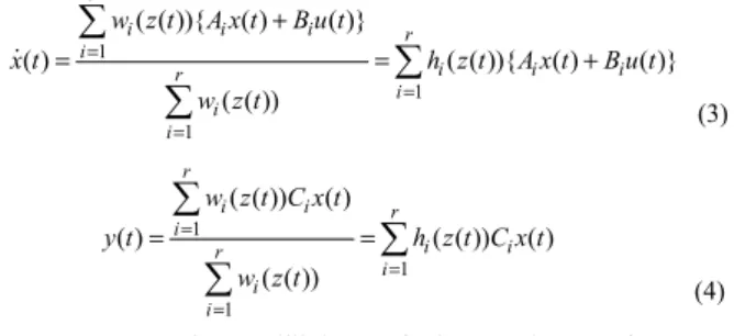
Given a pair of (x(t),u(t)), the fuzzy systems are inferred as follows:
1
1 1
( ( )){ ( ) ( )}
( ) ( ( )){ ( ) ( )}
( ( ))
r
i i i r
i r i i i
i i i
w z t A x t B u t
x t h z t A x t B u t
w z t
=
=
=
+
=
∑
= +∑ ∑
&
(3)
1
1 1
( ( )) ( )
( ) ( ( )) ( )
( ( ))
r
i i r
i r i i
i i i
w z t C x t
y t h z t C x t
w z t
=
=
=
=
∑
=∑ ∑
(4)THEOREM 1 The equilibrium of the continuous fuzzy control system described by (3) and (4) is globally asymptotically stable if there exists a common positive definite matrix P such that
0
( ) ( ) 0
2 2
iiT ii
ij ji T ij ji
G P PG
G G G G
P P + <
+ +
+ ≤ (5) if and only if the ith rule and jth rule have no overlap where i<j.
Assume there is a stable state feedback controller ui= −F X ti ( )
1
1 1
( ( )) ( )
( ) ( ( )) ( )
( ( )) r
i i r
i r i i
i i i
w z t F x t
u t h z t F x t
w z t
=
=
=
= −
∑
= −∑ ∑
(6)for the ith fuzzy rule.
Multiplying the inequality (5) on the left and right by P−1 and defining a new variable X=P−1and Mi=F Xi , we rewrite the conditions as
T T T 0
i i i i i i
XA A X M B B M
− − + + > (7) Now the problem changes to find the positive definite matrix X and M to satisfy the condition (7). This can be solved by LMIs by computer easily.
2.2 LMI Fuzzy control for ideal DC-DC converter
The ideal boost converter circuit [4] is as following Fig.1.
Fig. 1. The ideal boost converter circuit.
2009년도 대한전기학회 하계학술대회 논문집 2009. 7. 14 - 17
- 1728 -
1 2
2 1 2
(1 )1
1 1
(1 )
x u x E
L L
x u x x
C RC
= − − +
= − −
&
& (8)
where x is the current, 1 x is the output voltage.2
For the equilibrium pointx1r=Id , x2r=Vd and equilibrium point reference input r, substitute the totally control inputu u= 0+ , r
1 1 1r
x = +e x and x2= +e2 x2rinto (8), and then the error reference system as following:
1 2 2 0
2 1 2 1 0
(1 )1
1 1
(1 )
e r e x u
L L
e r e e x u
C RC C
= − − +
= − − −
&
& (9)
1 x2, 2 x1
z z
L C
= = − (10) If set (10), equation (9) can be rewritten as:
1 2 1 0
2 1 2 2 0
(1 )1
1 1
(1 )
e r e z u
L
e r e e z u
C RC
= − − +
= − − −
&
& (11)
As the monotonic of z and1 z are same, so that, the membership 2 function of the system can be simply written as:
1max 1 1 1min
1 2
1max 1min 1max 1min
2 max 2 2 max 2
3 4
2 max 2 min 2 max 2 min ,
,
z z
z z
M M
z z z z
z z z z
M M
z z z z
−
= − =
− −
− −
= =
− − (12)
where z1min, z1max, z2 minand z2 maxare the boundary of z and 1
z . Equation (11) canbe of the following form:2
0 1
( )
r r
i i i j i
i j
e M A e B M u
=
=
∑
× + ×∑
&
(13)
where
1 2 3 4
0 (1 )1
1 1
(1 )
r L
A A A A
r C RC
⎡ ⎤
⎢ − − ⎥
⎢ ⎥
= = = =
⎢ − − ⎥
⎢ ⎥
⎣ ⎦ , B1=[z1max z2 max],
2 [1max 2 min]
B = z z , B2=[z1min z2 max] and B2=[z1min z2 min] Using LMI toolbox calculates out controller parameters K.
By LMI, the control input is defined by (6) as
0i 1 1i 2 2i
u =k e +k e (14) Use inequality (7) and matlab LMI toolbox to calculate out the parameters k and1i k where i=1,2,3,4. In the following parts, the 2i totally controller for nominal system is defined as u t and has n( ) the format like (6).
2.3 Combination of LMI fuzzy and ISMC
Based on the SMC matching condition the system with disturbance is as follows:
1 2
2 1 2
( ) (1 ( ) ( ))1 ( )
1 1
( ) (1 ( ) ( )) ( ) ( )
x t u t d t x t E
L L
x t u t d t x t x t
C RC
= − − − +
= − − −
&
& (15)
where d is the disturbance.
The sliding surface is defined as:
2( ) 2n( ) 1( ) 1n( )
S=x t −x t +x t −x t (16) where x and1n x are states of nominal system.1n
Assume ( )u t =u tn( )+u ts( ) and derivate of S is:
1 2
2 1
1 ( ) ( ) ( ( ) 1 1 ) ( ) ( ) ( )
( )( ( ) ( ))
n n
n n
s
u t u t
S e t e t
C L RC
x t x t
u t d t
L C
− −
= + −
+ − +
&
(17) where e t1n( )=x t1( )−x t1n( ),e2n( )t =x t2( )−x2n( )t ,u t is the nominal n( ) control input and u is the sliding control input.s
The sliding controller finally is given out as:
1
1 2
2 max
1 ( ) ( ) 1
( ) ( )( ( ) (
1 ) ( )) ( )
n n
s n
n
u t u t
u t CL e t
Lx Cx C L
e t d sign s RC
− −
= +
−
− + (18)
where dmaxis the maximal absolute value of the disturbance.
2.4 Simulation
Use the model of (9) and controller design process in the above section with the typical parameters:,R=100Ω ,L=330mH,
12
E= V, C=2200μF, x1r=Id=0.48Aand x2r=Vd=24V. Based on SMC matching condition, a very big disturbance which is a sine waveform and the peak value is 727.27. Fig.2 shows the voltage output only using LMI fuzzy controller. Fig.3 shows the voltage output using LMI fuzzy based ISMC controller.
Fig. 2. The voltage output only Fig. 3. The voltage output using using LMI fuzzy controller. LMI fuzzy based on ISMC
3. 결 론
In this paper, the Fuzzy LMI based ISMC controller is used for DC-DC power converters.LMI fuzzy solved the initial big input for DC-DC converter from ISMC, while ISMC solved the problem of LMI fuzzy which is so dependent on fuzzy rules. The final results show that the combination control is efficient and perfect.
[참 고 문 헌]
[1] Peretz, M.M., Ben-Yaakov, S., "Revisiting the closed loop response of PWM converters controlled by voltage feedback,"Applied Power Electronics Conference and Exposition, Twenty-Third Annual IEEE, PP.58 – 64, Feb. 2008.
[2] Vazquez, N., Hernandez, C., Alvarez, J. and Arau, J., "Sliding mode control for DC/DC converters: a new sliding surface,"
Industrial Electronics, 2003. ISIE '03. 2003 IEEE International Symposium, vol.1, PP.422 – 426, June 2003.
[3] Ping-Zong Lin, Chun-Fei Hsu and Tsu-Tian Lee, "Type-2 Fuzzy Logic Controller Design for Buck DC-DC Converters," The 14th IEEE International Conference on Fuzzy Systems, PP.365 - 370, May 2005.
[4] Kanakasabai Viswanathan, Ramesh Oruganti and Dipti Srinivasan, "Nonlinear Function Controller: A Simple Alternative to Fuzzy Logic Controller for a Power Electronic Converter,"
IEEE TRANSACTIONS ON INDUSTRIAL ELECTRONICS, vol.52, PP. 1439 –1448, Oct. 2005.