- 788 -
A Permanent-Magnet Linear Motor Shape Optimal Design Using Coupling Particles Swarm Optimization
Nyambayar Baatar, Minh-Trien Pham, 고창섭 충북대학교 전기공학과
A Permanent-Magnet Linear Motor Shape Optimal Design Using Coupling Particles Swarm Optimization
Nyambayar Baatar, Minh-Trien Pham, 고창섭 충북대학교 전기공학과
Abstract - The cogging force of a permanent-magnet linear motor is a major component of the detent force, but unfortunately makes a ripple in the thrust force and induces undesired vibration and acoustic noise. In this paper, Coupling Particles Swarm Optimization is applied to optimization the shape of permanent magnet linear motor by minimizing the undesired vibration and acoustic noise in the thrust force and also considering the maximum thrust force. The result shows that the 9-pole 10-slot PMLM removes almost of the cogging force while giving a big thrust force.
1. Introduction
In recent years, permanent-magnet linear motors (PMLMs) have been widely used in many linear motional applications. The detent force comes from the unbalanced attractive force between the armature core and the permanent magnets regardless of the armature current. It has a periodic waveform according to the relative position of the armature core and the PMs. When an armature current is applied, the detent force is naturally added to a power force (the force generated by armature current). This makes a ripple in thrust force.
The ripple deteriorates the precise speed and position control for applications, especially at low speed operation as the ripple also induces undesirable vibrations and acoustic noises [1]. In the design stage of a PMLM, therefore, the detent force should be minimized. It is not easy to minimize the detent force and keeping the biggest stored energy. But using the unimodal optimization method such as GA, ES and PSO, there is only one optimum which can be found. So, we can not deal that problem. Therefore, it is necessary to design PMLM with multimodal optimization method. Coupling PSO can successfully locate all optima [2], is applied to minimize the detent force. After that, by considering the minimum detent force and maximum stored energy at the same time, the best solution is chosen.
In this paper, the PMLM having 9 PM poles, 10 winding slots, and corresponding proper winding scheme is optimized. The detent force in a PMLM is composed of end effect and cogging forces. The end effect force comes into existence only in a short primary type PMLM, as shown in Fig. 1, because of the electromagnetic interaction between the exterior teeth of the armature core and the permanent magnets [3]. The cogging force, on the other hand, is inevitable in both a short primary type and short secondary type PMLM because of the interaction between the interior teeth of the armature core and the PMs, as shown in Fig. 1, [4]. All the design parameters are shown in Table I.
By using the Coupling PSO, the optimal design of PMLM has proven to give the best solution when the cogging force and larger average thrust force are considered.
(C ogging force)
(E nd effect force) (C ogging force) (E nd e ffe ct force ) (E nd effect force) (E nd e ffe ct force ) Fig. 1. End effect force and cogging force in a short primary type
TABLE I
Specifications of an 9-Pole 10-Slot PMLM
Item Specification
Primary
Number of phase 3
Slot width 16.5(mm)
Slot pitch 25.2(mm)
Laminated width 70(mm)
Secondary
Pole pitch(τp) 28(mm)
PM height 4(mm)
PM width 21(mm)
Material NdFeB
Residual flux density 1.23(T)
Air-gap Mechanical tolerance 1.0(mm)
2. Coupling Particles Swarm Optimization Algorithm In the conventional PSO, the velocity of i-th particle is updated as follows [2]:
(1)
(2) where , , are the position, velocity and personal best position of the i-th particle, respectively, and g is the global best position, is the inertia, , are cognitive and social coefficients, and , are uniform random number within [0,1], and N is the total number of the particles. When the coefficient 2 is set to zero, equation (1) is called as cognition-only model.
The overall flow of the proposed Coupling PSO is summarized as follows:
Step 1. Initial particles
Initially N main particles are randomly generated, and allowed to move according to the cognition only model. Each main particle is expected to move toward not a global optimum point but its nearest local optimum point.
Step 2. Coupling
When a main particle updates its personal best position, i.e., when
is satisfied, it forms a i-th couple by generating a new particle near by itself as shown in Fig. 2. The position of the new particle is given randomly as follows:
(2) where r is a uniform random number within [0,1].
Step 3. Movement of a couple
The movement of a couple is just like that of a group in the Clustering PSO. The two particles in this i-th couple will move according to the following rule:
(3) 2009년도 대한전기학회 하계학술대회 논문집 2009. 7. 14 - 17
- 789 -
Variable [Unit]
x1 [mm]
x2 [mm]
R [mm]
Min 0 4 -
Max 14 21 -
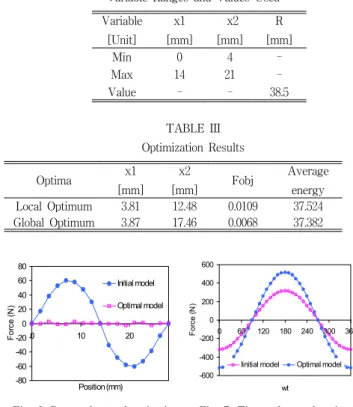
Value - - 38.5
Optima x1
[mm]
x2
[mm] Fobj Average
energy
Local Optimum 3.81 12.48 0.0109 37.524
Global Optimum 3.87 17.46 0.0068 37.382
where is the couple best position of k-th couple and is a uniform random number within [0,1], and is a very small number (for example, 10-4% of the design space). The last term is for non-stop-moving and becomes 1 only when the condition,
is satisfied for 3 consecutive iterations.
Optimum point pi(t-1)
xi(t) ci(t)
ck(t) cj(t) Rk
Rj Main particle to be eliminated
k-th couple j-th couple to be eliminated
ck(t) cj(t) Rk
Rj Main particle to be eliminated
k-th couple j-th couple to be eliminated
Fig. 2. Generation of a new particle. Fig. 3. Elimination.
Step 4. Elimination of a couple and main particle
When a couple or a main particle is very near to another couple, the couple or the main particle is eliminated as shown in Fig. 3. This process will increase the numerical efficiency of the proposed Coupling PSO.
Step 5. Stopping criterion
The k-th couple will stop its moving when its movement is very small (for example, less than of the design space) for 10 consecutive iterations and its couple best position will be an optimum.
The algorithm will be terminated when all couples stop without regard to main particles.
3. Application Example and Results
The proposed algorithm is applied to 9p10s PMLM shape optimization. As we known, the detent force is combined by cogging force and ending force. However, in this model, the end effect force is much bigger than cogging force as shown in Fig. 4. This is reason why in this paper, the detent force of model is minimized by considering the end effect force only.
-60 -40 -20 0 20 40 60
0 5 10 15 20 25
Position (mm)
Force (N)
Cogging force End force
S N S
N
τNNNNpp SSSS
τ
Fig. 4. End effect force and Cogging force Fig. 5. Design parameters To optimize the end effect force, there are two variables , which are described in Fig. 5 and the R is chosen 38.5 in mm for any and . The limitations of and are shown in Table II.
The detent force can be calculated as:
(4) where is the displacement [mm], W is the magnetic energy [J], B is the magnetic flux density [T], H is the magnetic field [A/m] and V is the volume [].In order to minimize the detent force. So, variation of the energy corresponding to different positions should be reduced. Hence we can consider the equation (5) as the objective function.
(5) where is average energy and is energy in i-th position.The Coupling PSO has been applied to solve this problem with the number of main particles are 30 and maximum number of iteration is 800. The optimization process required 2000 evaluations,
and returned 2 feasible optima including global optimum. They are shown in Table III, together with Average energy values (thrust force) and the total squared variation (objective function value).
From Table III, we can see that the first candidate is not a global optimum because the objective function value is bigger than that of the second candidate. However, the average energy of the local optimum is bigger than that of the global one. Therefore, the first candidate is selected as the solution of this problem.
As shown in Fig. 6 and Fig. 7, the detent force and the thrust force are improved.
TABLE II
Variable Ranges and Values Used
TABLE III Optimization Results
-80 -60 -40 -20 0 20 40 60 80
0 10 20
Position (mm)
Force (N)
Initial model Optimal model
-600 -400 -200 0 200 400 600
0 60 120 180 240 300 360
wt
Force (N)
Iinitial model Optimal model
Fig. 6. Detent force of optimal Fig. 7. Thrust force of optimal 4. Conclusion
The Coupling PSO is used to minimize the detent force in the 9p10s PMLM model. With the advantage of the Coupling PSO, multiple optima can be located. After that, by considering the maximum average energy, the local optimum is selected as the solution, not the global optimum as usual. The detent force of the optimal is much smaller than initial one. Moreover, the biggest average energy among these optima is also considered. Therefore, the thrust force of optimal is improved to the initial one. Consequently, the proposed Coupling PSO has good advantages in reduction the detent force also considering the big thrust force for the 9p10s PMLM
[References]
[1] R. D. Thornton, "Linear synchronous motor design," in Int. Electr.
Machines Drives Conf., San Antonio, TX, May 2005, pp. 15551560.
[2] Minh-Trien Pham, Nyambayar Baatar, 고창섭, "Couple Particle Swarm Optimization for Multimodal Functions" Proceeding of the KIEE EMECS Annual Autumn Conference 2008
[3] M. Inoue and K. Sato, "An approach to a suitable stator length for minimizing the detent force of permanent magnet linear synchronous motors," IEEE Trans. Magn., vol. 36, no. 4, pp.
18901893, Jul. 2000.
[4] T. Yoshimura, H. J. Kim, M. Watada, S. Torii, and D. Ebihara,
"Analysis of the reduction of detent force in a permanent magnet linear synchronous motor," IEEE Trans. Magn., vol. 31, no. 6, pp.
30423044, Nov. 1995.