ⓒ IEMEK J. Embed. Sys. Appl. 2016 Apr. 11(2) 67-78 ISSN : 1975-5066
http://dx.doi.org/10.14372/IEMEK.2016.11.2.67
Ⅰ. Introduction
Due to the power consumption, leakage current and heat dissipation, system on a chip technology evolves to many-core systems. The main reason of this evolution is that the leakage power increases ten times greater than in previous chip technology and becomes a major determinant of a single processing system. In addition, software applications required by the market have been evolved into
providing diverse functions with complex design and bigger size. Thus, multi-core and many-core systems consists of heterogeneous components to meet the complex requirements.
Memory technology also evolves with the heterogeneous processing components. As a result, SRAM-based caches are no longer suitable for the many-core system with high leakage and power consumption.
There are various alternative memory technology such as Phase-Change RAM (PCRAM), Magnetic RAM (MRAM), Spin-Transfer Torque MRAM (STT-RAM) and Resistive RAM (RRAM). A well-known successful technology is to use Spin-Transfer Torque RAM (STT-RAM) as a baseline technology for the cache architecture. The STT-RAM cell has a density that is higher by about four times and consumes nearly zero leakage power compared to the counterpart of the SRAM cell [1]. However, current implementations of this promising alternative
An Efficient Variable Rearrangement Technique for STT-RAM Based Hybrid Caches
Jonghee M. Youn, Doosan Cho*
Abstract : The emerging Spin-Transfer Torque RAM (STT-RAM) is a promising component that can be used to improve the efficiency as a result of its high storage density and low leakage power. However, the state-of-the-art STT-RAM is not ready to replace SRAM technology due to the negative effect of its write operations. The write operations require longer latency and more power than the same operations in SRAM. Therefore, a hybrid cache with SRAM and STT-RAM technologies is proposed to obtain the benefits of STT-RAM while minimizing its negative effects by using SRAM. To efficiently use of the hybrid cache, it is important to place write intensive data onto the cache. Such data should be placed on SRAM to minimize the negative effect. Thus, we propose a technique that optimizes placement of data in main memory.
It drives the proper combination of advantages and disadvantages for SRAM and STT-RAM in the hybrid cache. As a result of the proposed technique, write intensive data are loaded to SRAM and read intensive data are loaded to STT-RAM. In addition, our technique also optimizes temporal locality to minimize conflict misses. Therefore, it improves performance and energy consumption of the hybrid cache architecture in a certain range.
Keywords : Cache, Memory subsystem, Variable, Performance, Energy
*Doosan Cho ([email protected])
Received: 27 Jan. 2016, Revised: 9 Mar. 2016, Accepted: 28 Mar. 2016.
Jonghee Youn: CSE, Yeungnam University Doosan Cho: EE, Sunchon National University
※ This research was supported by the Basic
Science Research Program through the
National Research Foundation of Korea (NRF)
funded by the Ministry of Education
(NRF-2015R1C1A1A02037561).
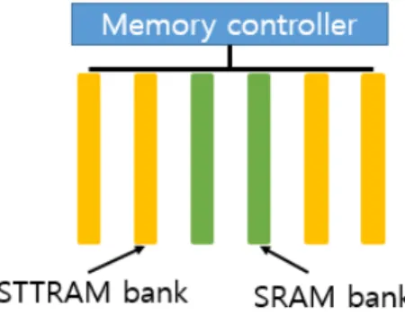
Fig. 1 Hybrid cache architecture
memory suffer from an important issue that its cells require relatively large energy and access latency when performing a write operation. It limits the ability to meet the requirements for the memory access latency in high performance many-core systems. That is, SRAM cell is much more efficient for write operations with improved power consumption, performance and endurance compared to STT-RAM cells, even though the cell size is four times lager.
In order to obtain the advantage of these two types of RAMs, we compose a set of caches that are configured with a small number of SRAM lines and many STT-RAM lines in a hybrid manner as shown in Fig. 1 SRAM is responsible to handle the frequently recorded data blocks that constitute a major part of the write operations in an application while STT-RAM hides the memory access latency by increasing the capacity of this hybrid cache.
The detailed structure and its operation procedure is beyond the scope of this paper.
Work [2] presents the detailed hybrid cache architecture and its characteristics.
In this study, we propose an efficient cache management technique for the hybrid cache that identifies write-intensive data blocks and rearranges the location of such data blocks for these to be placed in SRAM lines. Other data can be categorized as less-write or read-intensive data, they should be placed in STT-RAM lines. In order to determine an optimum data placement onto SRAM or
STT-RAM, cache conflict misses should also be countered. The proposed technique measures the conflict misses as a metric to determine data placements in each cache line.
Thus, our technique takes advantages of the hybrid cache while ensuring minimal cache misses.
A number of similar studies have been proposed to alleviate negative effects of the hybrid cache. On architecture design point of view, various Non-Volatile Memories (NVMs) have also been proposed to be used in hybrid cache. Mangalagiri [3] proposed PCM based a hybrid cache architecture. Dong [1] evaluated 3D MRAM architecture as on-chip cache. Joo [4] presented energy/endurance aware PCM based cache design. In these works, they all considered NVM as cache for current microarchitectures, and naturally they imply that it is technically feasible to integrate NVMs with SRAM into on-chip memory.
In system management point of view, there are a number of similar studies to minimize the drawback of STT-RAM which caused by the write activities. Reducing the number of write activities to NVM (like STT-RAM) can lower the negative effect of STT-RAM. Thus, a data placement technique is essential to reduce the number of write activities on STT-RAM.
Studies [1-6] show that hybrid caches with
proper data rearrangement policies consumes
less power than traditional cache. However,
the cache rearrangement policies leads too
much overhead since the policies did not make
full use of many known characteristics of data
access pattern in embedded applications. That
is, their works focus on reducing power
consumption as an only objective function. As
a result, it yields negative side effect in cache
hit ratio. Our approach differs from the
existing works in that ours improve energy
consumption by reducing the write activities on
STT-RAM without increasing any cache
misses. Because this work optimize relative
placement of write intensive variables with
their cache conflict counts.
Specifically, data access information can be captured by profiling, and based on such information write-intensive data can be identified. The negative effect of hybrid cache can be reduced by placing such write-intensive data on SRAM. At this moment, our technique provides conflict aware data placement to lower cache conflict misses. In experiment, it is achieved that 6% performance improvement and 5% energy saving.
The rest of this paper is organized as follows. Section 2 introduces the overview of the proposed technique. Section 3 presents a detailed optimization process to determine the variables placement. The experimental results are presented in Section 4, and finally, the conclusion is presented in Section 5.
Ⅱ. The Proposed Technique
Our technique relies on the insight that addresses are assigned to data when created.
Specifically, the addresses of the global and local variables are determined during the compile-time. The addresses that are assigned for the data have an effect on the performance of the data cache, and therefore, it is important to find an optimally relative data placement at compile time that can lead to a positive effect on the performance of the system. Before mentioning the detail of the proposed technique, it should explain how to identify stack variables belonging to the same cache line. We use the same procedure of existing work [7] for this as follows. At compilation time, we know each variable’s offset relative to the stack base pointer, but cannot determine which group of data objects belong to the same cache line. If the stack base pointer for each function is aligned with the cache line size, it will be easy to correctly identify which group of data objects belong to the same cache line according to the offset addresses relative to the stack base pointer. In this work, two tasks are carried out to the
stack base pointer. First, extra instructions are inserted at the entry of the main function to align the stack base pointer of the main function with the cache line size. Second, the stack size of each user function is expanded to be a multiple of the cache line size. Assume that the cache line size is C, and the original stack of a function is x. After expansion, the new stack size for this function is . After these two tasks, it is guaranteed that the stack base pointer of each user function invocation is aligned with the cache line size. After this alignment work, it is easy to identify variables that belong to the same cache line. We only need to test whether the offsets of these two variables divided by the cache line size are the same value. By doing this, we can optimize local stack variables correctly.
Traditional data placement decision is followed by alphabetical order or variable declaration order without considering cache design. It yields inefficiency of cache performance. As earlier mentioned, it is essential to use of hybrid cache that is to identify write-intensive data and to place them into SRAM. To that end, our technique classifies data into either the write-intensive group or read-intensive group. And then, data can be partitioned into the STT-RAM for read-intensive group or into the SRAM for the write-intensive group. At the data placement decision on each cache component, temporal locality of data should be considered, since it affects cache conflict miss in the same cache line. To determine relative placement of variables on each cache, we define and use a variable conflict graph. It represents the number of cache conflicts between pairs of variables. Using the graph on hybrid cache architecture, we can determine variables’
placement to lower the cache conflicts. By
doing so, this promising technique can improve
the efficacy of STT-RAM based hybrid caches.
To achieve this goal, we build two tasks as follows:
1. Data classification – grouping variables to write-intensive variables and read-intensive variables
2. Placement decision – placing variables on the hybrid cache, specifically it determines the variable’s placement order in each cache line
To build the first task, data usage (access type, access frequency) information should be extracted from applications in execution time.
We use an existing profiling technique to extract such information in runtime [8]. The profiles utilize a data structure for all global/local variables. The profiles includes the name, reference count, size, access footprint, and life-time information of the variable as well as the execution sequence of the procedures. Once the profiles have been generated they are fed back into the compiler in order to process of the variables placement optimization. In this study, we interchangeably use the term ‘data’ and ‘variables’, and we treat the stack and the global variables as a single contiguous object.
The second task is designed to lower cache conflict misses by replacing variables on the hybrid cache lines. The replace task performs to load variables with high conflicts into the same cache line at the same time. Thus, the number of conflict misses can be reduced. To measure of the conflict, we use a variable conflict graph that represents the number of conflicts between variables. To efficiently represent the conflict relation between variables, it is a necessary to extract control flow information for target applications. To summarize such control flow information for a given application, we build a procedure call descriptor (PCD) that is generated by profiling.
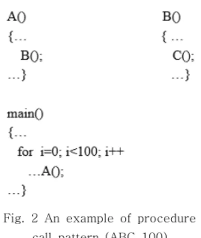
The procedure call descriptor represents a trace of procedure calls, and it is designed to precisely summarize the procedure call pattern
Fig. 2 An example of procedure call pattern (ABC_100)
and to enable analysis techniques in order to expose the simplicity of the procedure call patterns.
For instance, there is a procedure call trace
“A B C F A B C F A B C F …”. That can be represented as ABCF_32. As shown in Fig. 2, PCD represents a procedure sequence that is recurrently called, and the count represents the total number of times that the pattern is called during the execution of the program.
PCD has several attractive properties in that it is simple, fast and works quite well if the procedure calls have predominantly linear patterns. We have noticed that, in practice, a significant portion of instructions exhibit a linear call behavior and hence can be captured by a small number of descriptors.
Traversing PCDs, our technique builds Variable Conflict Graph (VCG). VCG provides enabling information that identifies variables to yields cache conflict misses. Such variables should be loaded in the same cache line at the same time to reduce cache conflict misses.
To this end, VCG consists of three components, node, edge and weight. Node is a unique variable used in a procedure. Edge is created if a pair of variables has conflict relation. Weight represents the number of cache conflict in pairs of nodes.
When all VCGs have been created for each
PCD, then, write-intensive variables should be
identified in the generated VCGs. Each unique
Fig. 3 A criterion for write-intensive variable identification
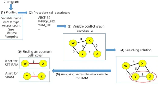
Fig. 4 The overall workflow of the proposed technique
variable obtains its own read/write frequency from profiled information. Based on the access frequency, write-intensive variables can be identified with the criterion shown in Fig. 3 Energy_STT-RAM shows energy consumption of the given variable V. Energy_SRAM also shows the energy consumption corresponding to the read/write counts. In this study, this criterion is empirically determined through several runs of the application. If it is determined to too small, the amount of data to be forced to assign into the SRAM becomes too large to store. In the opposite case, variables placed in the STT-RAM requires lots of the write operations. The either case makes worse in the performance of the hybrid cache.
Therefore, the criterion should be carefully determined according to characteristics of the given application. We design the criterion that captures a certain benefit from partitioning
write-intensive variable placed onto SRAM.
After done of this identification, VCG should be partitioned to either write-intensive group or not. And then, the partitioned variable conflict graphs for write-intensive group (WIG) are assigned to SRAM until there is available space. Hybrid cache consists of limited SRAM lines, thus, frequently accessed partitioned VCGs for WIG are preferentially assigned to SRAM line by greedy approach. The other partitioned VCGs are assigned to STT-RAM.
Now, it is the time to determine relative
variable ordering in each STT-RAM cache
lines and SRAM cache lines. In order to
determine the relative placement in the cache
lines, we use a maximum weighted path
cover(MWPC) algorithm to find an optimal
placement with the partitioned VCGs. The
solution of MWPC is the final placement to
lower conflict cache misses.
Our technique optimizes placement of variables to improve the cache performance at compile time. It statically identifies variables that have high probability to yield cache conflicts. They should be placed in the same cache lines to reduce conflict misses. Thus, compiler places such variables closely in the order of a maximum weight path on partitioned VCGs.
Fig. 4 shows the overall workflow of our technique. In the figure, Fig. 4 (1) describes profiled information for the proposed technique.
Fig. 4 (2) shows generated PCDs for a target application. Fig. 4 (3) illustrates a VCG for a certain procedure. Fig. 4 (4) shows a result of write-intensive variable’s identification. Fig. 4 (5) describes assigning write-intensive data to SRAM. Fig. 4 (6) illustrates finding a variable placement to lower conflict cache miss.
In order to reduce the cache miss rate, our data rearrangement technique must be able to provide one important capability. This capability is to find better placements of variables in data section, and to determine line numbers to be placed in the cache. The placement of local and global variables are determined at compile time. Thus, the proposed technique is designed as a compile time optimization technique.
Ⅲ. Optimization of the Variable Placement
As described in the previous section, the proposed technique consists of two tasks. The first task is write-intensive variable identification. The next task is variable rearrangement in a target application to lower cache conflict misses. In order to efficiently design the tasks, we formally define the variable rearrangement problem (VRP) to maximize the efficiency of the hybrid cache.
Given a set of variables in target applications, the optimization problem finds an optimal variable placement while minimizing the cache
misses, and the maximum STT-RAM read access achieves an optimum performance of the given cache.
Problem (VRP): For a set local/global variables in an application code, the VPP determines the ordering of the variable placements while satisfying the program correctness (satisfying the dependence constraint). There are two sets of variables:
write-intensive variable (WIV) set, a read-intensive variable (RIV) set. An optimal ordering of the given variable sets in this problem can be provided by the object function as follows:
Objective Function 1.
Optimum_Variable_Ordering = MINIMUM(
STTRAM_MISS(WIV_Ordering) + SRAM_MISS(RIV_Ordering) )
The objective function stands to minimize the cache conflict misses by reordering variables in STT-RAM cache and SRAM cache.
To solve the given problem. Our technique constructs a graph, called the variable conflict graph (VCG), which represents cache conflict relations between variables. Based on the conflict information, we can determine variables’ relative placement to minimize conflict misses.
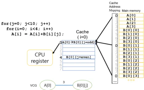
A VCG node represents a unique variable. A value on edges represents the number of cache conflicts that occur if the two variables are mapped to the same cache line. Fig. 5 shows an example of VCG construction. Based on the VCG, the variable placement optimizer reorders relative placements of variables in data section of a target program. After the rearrangement, it provides reduced cache conflict misses.
For fully associative caches the main source
of misses are the capacity misses. In direct
mapped caches, also misses can be due to
Fig. 5 An example of VCG construction
data conflicting in the same cache locations.
Direct mapped caches assign a unique location in the cache to each address in main memory.
Fig. 5 shows two arrays, and how they are typically organized in memory by the compiler.
The Figure also shows how for the iterations of the inner loop, the elements accessed by the algorithm are mapped in the cache: When j takes even values, the elements of the B array are mapped in location no.4. However, when j takes odd values, these are assigned in location no.0, hence conflicting with the element of array A. Therefore, after loading in the cache the element of array A, this has to be flushed to accommodate the elements of array B. This in itself would not be a problem if the element of array A, would not be needed in subsequent iterations. Unfortunately, this is the case, hence creating a conflict miss in which the same element of array A needs to be loaded and flushed several times. This is true for all elements of array A.
In order to represent the conflict relation among the variables of the VCG, an equation is necessary to evaluate the number of conflicts as shown in Fig. 5 This equation should accurately estimate the number of cache
conflicts caused by a result of placing variables in the same cache line. The cache maps a variable to a cache line according to the following function:
Equation 1.
Cache(address) = memoryAddress mod(
cacheSize/(associativity * wordPerLine))
A variable can be mapped to a cache line according to its memory address and data type. A pair of variables potentially conflict when they are placed to the same cache line at the different time, and it can be represented by a graph. To this end, we use the Variable Conflict Graph (VCG) which is defined as follows:
Definition 1. (VCG) variable conflict graph G = (N, E) is an undirected weighted graph.
There are node set N = {
,…,
} and edge
set E = {
,…,
}. Each node
in G
represents to a unique variable of a target
program. An edge
from node
to
is
created when they yields the conflict on the
same cache line driven by the given cache
rearrangement policy. The weight of the edge
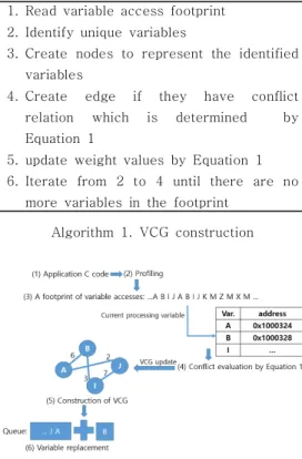
1. Read variable access footprint 2. Identify unique variables
3. Create nodes to represent the identified variables
4. Create edge if they have conflict relation which is determined by Equation 1
5. update weight values by Equation 1 6. Iterate from 2 to 4 until there are no
more variables in the footprint Algorithm 1. VCG construction
Fig. 6 Construction of VCG
is the number of conflicts on a certain cache line due to
and
.
As shown in Fig. 5, variable conflict graph is an undirected weighted graph that represents conflict relation occurred by variables’ placement in data section of the given binary code. This graph is constructed by the profiled information from the target application.
The process of VCG construction is as follows. First of all, the profiler generates access footprint for each variable in a program. The footprint summarizes the access order of each variable, and their address in data section. In the beginning of VCG construction, there are no VCG nodes, thus, it creates nodes for all unique variables. After node creation, it updates the value of the conflicts. As shown in Fig. 6 (3), (4), it is checked whether there are conflicts between the currently processed variable and the others
Input: PCD, variable access footprint Output: variable placement layout in data section of the given application 1. Traversing PCD
2. Building VCGs for each procedure by algorithm 1
3. Identifying WIV for each VCG by using the metric described in Fig. 3
4. Partitioning VCGs into WIV group and RIV group
5. Find the maximum weight path cover for the partitioned VCG
6. Reorder the variable placement followed by the path cover result
Algorithm 2. Data reordering algorithm
by using Equation 1. Then, the number of conflicts of the variables are updated to weights of VCG. Until there are no more variables on the footprint, these VCG node creation and conflict weight update are repeated.
The queue as shown Fig. 6 (6) is used to obtain information of variables in order to replace by the capacity constraint. This queue stores the order to be replaced variables by the cache rearrangement policy in the case of when VCG grows bigger than cache size. When capacity cache miss begins, then new VCG construction should be started.
We mentioned earlier that our technique minimizes the cache conflict misses to improve the performance of the hybrid cache. Algorithm 2 describes the proposed technique as follows.
The first step is VCG construction as shown in
Algorithm 2. After construction of VCG, WIV
identification is performed to place high cost
required variables into SRAM. As described in
Fig. 3, WIV sets can be captured based on
profiled information. And then, the partitioning
of VCG is performed with cutting by identified
WIVs in the graphs. As earlier mentioned,
write-intensive variables should be placed in
SRAM since the cost of the write operation in
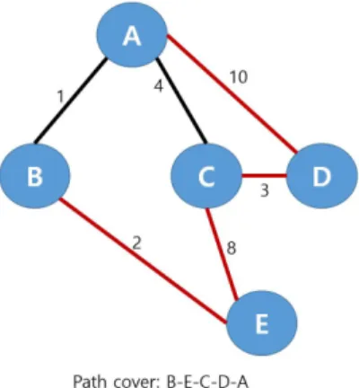
Fig. 7 A path cover on the VCG
STT-RAM is relatively high. Thus, this VCG partitioning effectively improves the performance of the hybrid cache. In order to achieve this benefit, it is necessary to adopt a criterion to determine the write-intensive variable. We carefully design the criterion as described in Fig. 3 Based on the result of WIV identification, VCG can be partitioned. After VCG partition, our technique determines the relative placement of the variables in data section. It is provided by a result of a maximum weighted path cover (MWPC) on the partitioned VCG. MWPC is performed by following steps.
Initially, we have an empty path P and a set of nodes in the partitioned VCGs. For each iteration, we select an edge in the node among the “candidate” edges, expand P by including the edge to P, and update the elements of a node by merging the two end nodes of the edge into a path as a relative placement. More precisely, in the ith iteration of the algorithm, for every edge (vi, vj ) in the VCGs such that the inclusion of (vi, vj) to P does not cause a cycle in the initial VCG, the variables corresponding to vi and vj are merged into a path to compute the total weight. The weight represents the number of conflict misses involved in P. After the weight summation, we select the edge (vi, vj) with the largest weight value among the candidate edges and merge the vi and vj variables into q group. P is then
updated by including (vi, vj), and VCG is also updated by merging the vi and vj nodes and updating the connected edges accordingly. The process is repeated until P becomes a path that covers all the nodes in the set of node in the VCGs. Finally, the path that covers the variables placement in an optimum order is created as a placement solution shown in Fig. 7.
This final placement mitigates the cache conflicts by closely grouping such variables that incur a cache conflicts among them.
Ⅳ. Experimental Results
The proposed compilation techniques are implemented using LLVM [9], which is an open source compiler infrastructure. Two groups of executables are generated and the related statistics are collected. The first group is referred to as the Original Group (ORG) and is compiled by the LLVM compiler using the default data placement method. The second group is called the Optimized Group (OPG) and is compiled by the LLVM compiler, giving write-intensive data preference for loading into the SRAM cache lines and improving cache conflict misses by optimizing the variables placement. We use ORG as a baseline technique to evaluate the proposed technique.
For both groups, the “O3” optimization is enabled in LLVM. Benchmarks as well as input files are selected from the LLVM test suite, originated mainly from some industrial codes [10]. By profiling, characteristics of benchmark programs are obtained such as the frequency of references to variables, espresso (24617), gcc (17436), compress (51).
A pin-based cache simulator was developed
for the experimental evaluation. Pin is a tool
for dynamic instrumentation of the programs
[11]. The cache simulator with a cache
management strategy from [12] is implemented
for the experimental evaluation. The simulator
targets the one-level data cache in single-core
processors, and the target architecture is
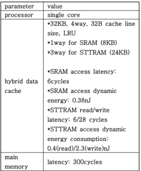
parameter value processor single core
hybrid data cache
*32KB, 4way, 32B cache line size, LRU
*1way for SRAM (8KB)
*3way for STTRAM (24KB)
*SRAM access latency:
6cycles
*SRAM access dynamic energy: 0.38nJ
*STTRAM read/write latency: 6/28 cycles
*STTRAM access dynamic energy consumption:
0.4(read)/2.3(write)nJ main
memory latency: 300cycles Table 1. Architecture parameters
program D-miss (ORG)
D-miss (OPG)
total reduction
of cache miss ratio compress
(input1) 10.92 7.38 32.40
gcc(input1) 8.47 7.28 14.06
espresso
(input1) 5.74 5.41 1.04
compress
(input2) 15.21 12.11 20.41
gcc(input2) 7.66 6.28 18.05
espresso
(input2) 3.11 2.43 21.86
Table 2. Data cache miss rates
depicted in Table 1. The cache parameters and memory parameters are obtained from a modified CACTI [13].
In this experiments, we try to prove the effectiveness of our technique. First, it should be illustrate the result of write-intensive variable partitioning. By the partitioning, WIVs are placed on SRAM to reduce expensive cost of the write operation in the hybrid cache.
Thus, we show the result of this task in Fig. 8.
Fig. 8 Reduction of total latency and write accesses in STT-RAM
It is from comparison between STT-RAM technique (ours) and traditional data placement technique. Second, it should be evaluated the variable reordering to reduce cache conflict miss by using VCG. Table 2 shows the results of OPG, that the proposed technology is applied to the benchmarks, compared to the cache miss ratio of ORG. Six times of experiments were conducted using three program codes with two different inputs.
As shown in Table 2, the column of D-MISS (ORG) shows its cache miss ratio from 3.1% to 15.2%. The column of D-MISS (OPG) shows its cache miss ratio from 2.4% to 12.1%. As shown in the last column of Table 2, D-MISS (ORG) is improved from 1% upto 32.4% in the all studied cases. Espresso shows the lowest reduction with input 1. In that case, there are less write intensive data with small data set. Thus, less rearranging is performed.
This experiments proved that the proposed technique can effectively optimize the relative placements of the frequently used variables in the data section.
The OPG results shown in Fig. 8 are
normalized to the baseline of ORG. As shown
in Fig. 8, the proposed techniques can
significantly reduce the number of write
operations in STT-RAM. This reduction, up to
21.8%, 10% on average, can significantly save
the cost since the write operations in
STT-RAM have longer latency than those in
the SRAM. The proposed technique could
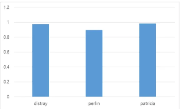
Fig. 9 Reduction of the energy consumption
reduce write accesses to STT-RAM. As a result, total latency can be improved by 6%.
Therefore, it is promising that the proposed technique can improve the efficiency of the STT-RAM based hybrid cache memory subsystems. Fig. 9 shows that the overall energy saving result corresponding to the reduction of cache conflict misses and WIV partitioning to place them on SRAM. As shown in the Figure, the proposed technique can achieve 5% energy saving by effective data rearrangement for the hybrid cache architecture.
Ⅴ. Conclusions
In this study, we introduce a technique that uses a compiler-based approach to improve energy consumption by rearranging variables in main memory space for STT-RAM based the hybrid cache. To that end, we present a PCD (procedure call descriptor) which illustrates repeated usage pattern of procedures and the number of its execution count. Traversing the PCD, rearrangement of local variables (stack data) is performed for each procedure, in order to maximize the benefits of the hybrid cache structure. The variables’ placement are determined by the variables’ cache conflict graph. A value of an edge represents the number of cache conflicts between them. Thus, the proposed technique replaces the variables having high conflict relation to be located in the same cache line at the same time. By
doing this, it is possible to improve the cache miss ratio. The experiment shows that the proposed technique is able to improve cache miss rate upto 18% in the hybrid cache structure.
References
Jonghee M. Youn (윤 종 희)
He received Ph.D. de- grees in EECS from Seoul National University, Korea, in 2011. He is currently an Assitant Professor with Computer Science and Engineering, Yeungnam Univ. His research interests are Compiler, Software Optimization, Security, Malware Analysis, System Software and Embedded System (architecture/soft- ware).
Email: [email protected]
Doosan Cho (조 두 산)
He received Ph.D. de- grees in EECS from Seoul National University, Korea, in 2009. He is currently an Associate Professor with the Department of Electrical and Electronic Engineering, Sunchon National University, Sunchon, Korea. His research interests include machine learning and low power system.
Email: [email protected]