1)
1. Introduction
Photocatalytic oxidation, which is one of remarkable technologies of water pollution control, with the char- acteristics of high efficiency, low energy consumption and a wide range of application, can oxidize most or- ganic compounds, especially non-biodegradable organic contaminants, by mineralizing them to small inorganic molecules. For this reason, photocatalytic oxidation technology has broad prospects for application. Among
various semiconductor photocatalysts, there is a general consensus among researchers that TiO
2is more superi- or because of its high activity, large stability to light illumination, and low price[1-4]. In photocatalytic deg- radation, two modes of TiO
2application are adopted:
(1) TiO
2immobilized on support materials, and (2) TiO
2suspended in aqueous medium[5,6]. Application of TiO
2in suspension instead of immobilizing the TiO
2on solid carriers has shown an improvement in organic degradation efficiencies due to the uniform distribution
†
Corresponding author(e-mail: [email protected], http://orcid.org/0000-0002-7104-9659)
Hybrid Water/Wastewater Treatment Process of Membrane and Photocatalyst
Jin Yong Park
†Dept. of Environmental Sciences & Biotechnology, Hallym University, Gangwon 24252, Korea (Received June 11, 2018, Revised June 25, 2018, Accepted June 25, 2018)
요 약: 본 총설은 다양한 저널 게재 논문으로부터 분리막 및 광촉매의 혼성 정수/하수 처리 공정을 요약하였다. 이 총설 에는 (1) 분리막 광촉매 반응기(membrane photoreactor, MPR), (2) 분리막 결합 광촉매 공정에서 막오염 관리, (3) 유기 오염 물의 분해를 위한 광촉매 분리막 반응기, (4) 정수처리용 막분리 공정과 광촉매 분해의 결합, (5) 휴믹산 분해를 위한 광촉매 및 세라믹 막여과의 혼성공정, (6) 활성슬러지 여과를 위한 한외여과의 막오염에 이산화티타늄 나노입자의 영향, (7) 정수처 리용 광촉매 및 정밀여과의 혼성시스템, (8) 선박 평형수 처리용 한외여과 및 광촉매의 혼성공정 및 (9) 분리막 및 광촉매 코 팅 프로필렌 구의 혼성수처리 공정이 포함되어 있다.
Abstract: In this review article, hybrid water/wastewater treatment processes of membrane and photocatalyst were sum- marized from papers published in various journals. It included (1) membrane photoreactor (MPR), (2) fouling control of a membrane coupled photocatalytic process, (3) photocatalytic membrane reactors for degradation of organic pollutants, (4) in- tegration of photocatalysis with membrane processes for purification of water, (5) hybrid photocatalysis and ceramic mem- brane filtration process for humic acid degradation, (6) effect of TiO
2nanoparticles on fouling mitigation of ultrafiltration membranes for activated sludge filtration, (7) hybrid photocatalysis/submerged microfiltration membrane system for drinking water treatment, (8) purification of bilge water by hybrid ultrafiltration and photocatalytic processes, and (9) Hybrid water treatment process of membrane and photocatalyst-coated polypropylene bead.
Keywords: Membrane, Photocatalyst, Hybrid process, Water treatment, Wastewater treatment
and large specific surface area. However, classical sol- id-liquid separation processes such as sedimentation, centrifugation and coagulation used for separation of the fine TiO
2particles (typically less than 1 µm), are not effective[7]. In addition to the low reutilization rate, there is also a chance of secondary pollution caused by fine TiO
2particles in the effluent. Therefore, the recovery of the photocatalysts is one of the main concerns that affect its engineering application on a large scale. A lot of investigations have been con- ducted aiming at solving this problem[8-12].
In recent 15 years, titanium microsphere has also been proposed as a means to recover TiO
2photocatalyst. Generally the core-shell structured TiO
2microspheres with a mesoporous surface made of nano-TiO
2, have low density, high specific surface area and large size favorable for separation[13-16]. But the preparation method and operating conditions have great effect on particle morphology associated with photo- catalysis, and many problems existing in the current preparation methods need to be solved by optimizing the process conditions or developing new ones[17].
Membrane separation process for separation and pu- rification has been developed dramatically during the past few decades. It can simultaneously separate and concentrate all pollutants in water by the retention of its microspores without secondary pollution and phase change. In addition, with the advantage of low energy consumption, its equipment is compact, easy to operate and capable of continuous operation at room temper- ature[18]. However, membrane fouling due to the ad- sorption-precipitation of organic and inorganic com- pounds onto membranes leads to a decrease in the per- meate flux, an increase in membrane cleaning costs and a reduction of the life of the membrane. Although considerable progress has been made in membrane fouling[19,20], techniques for controlling membrane fouling remain inadequate, which is the major obstacle in the successful implementation of membrane separa- tion technology. The TiO
2photocatalysis-membrane separation coupling technology emerged recently can solve the two problems mentioned above effectively
[21]. The coupling technology not only keeps the char- acteristics and capacity of the two technologies, but al- so produces some synergistic effects to overcome the drawbacks of the single technology. On the one hand, the pollutants are oxidized by the photocatalysis, and the selected membranes show the capability not only to retain the photocatalyst, but also to reject partially or- ganic species by controlling the residence time in the reacting system. In other words, the membrane is also a selective barrier for the molecules to be degraded, thus the coupling technology could enhance the photo- catalytic efficiency and achieve excellent effluent quality. On the other hand, the coupling of photo- catalysis and membrane separation could solve or alle- viate the problem of flux decline associated with mem- brane fouling[22].
In this review article, the researches for hybrid wa- ter/wastewater treatment process of membrane and pho- tocatalyst were summarized from various journal publications.
2. Membrane Photoreactor (MPR)
K. Azrague et al.[10] described the combination of a dialysis membrane and a photochemical reactor into a MPR to mineralize organic compounds. With this proc- ess, a pollutant model (2,4-dihydroxy benzoic acid) was mineralized from turbid waters in the photoreactor by using V-UV (vacuum ultra violet) irradiation (172 nm). This “advanced oxidation processes” produced high concentrations of hydroxyl radicals and was a good method to mineralize organic compounds. A model based on diffusion through the membrane and first order reaction in the reactor was in good agree- ment with the experimental data, in a wide range of operating conditions.
Irradiation was carried out in a DEMA (Mangels, Born-heim-Roisdorf, Germany) 13/12 Solidex glass an- nular photoreactor containing 350 cm
3of solution. K.
Azrague et al.[10] used Xe-excimer light source,
so-called high-pressure dielectric barrier discharge lamp.
This quasi-monochromatic xenon excimer lamp is of cylindrical geometry, built of two concentric Suprasil quartz tubes with a total length of 25 cm and external diameter of 3 cm. It was positioned in the axis of the photoreactor and cooled water was circulated in the lamp jacked[10], as shown in Fig. 1.
A typical degradation curve is presented in Fig. 2 and corresponds to the degradation of the pollutant model in batch mode. The apparent constant of degra- dation (k
app) = 1.05 × 10
-3/s has been obtained from this curve (pseudo-first order) and this value will be used when modelling the degradation of 2,4-DHBA in the MPR[10].
Fig. 3 shows the membrane photoreactor system.
The photoreactor was the same as for the batch irradi-
ation experiments. A pump continuously re-circulated the turbid water from the feed tank tangentially to the membrane and an other pump continuously re-circulated the clear water through the photoreactor inside the hol- low fibres. Recirculation rates are adjusted in such a way that no convection was observed during one ex- periment[10]. The membrane used in all experiments was made of polyacrilonitrile hollow-fibers (PAN 650 SF Asahi Medical) of 200 µm in diameter and 35 mm in length. The molecular weight cut-off was 11,800 g/mol and the module is 1.3 m
2in area[10].
Fig. 1. V-UV photoreactor : (1) power supply, (2) V-UV lamp, (3) oxygen inlet[10].
Fig. 2. Kinetic of V-UV degradation of 2,4-DHBA with batch irradiation experiment[10].
Fig. 3. Schematic diagram of the MPR: (1) feed tank, (2) circulation pump, (3) flow meter, (4) pressure gauge, (5) hollow fibres module, (6) V-UV photoreactor, (7) oxygen cylinder, (8) blocking valve, (9) magnetic stirrer, (10) cooling device[10].
Fig. 4. Experimental and calculated concentrations in
2,4-DHBA vs. irradiation time with PMR (▲ : in turbid
feed tank (bentonite: 3 g/L); ● : in photoreactor)[10].
To mimic turbid water, they chose a bentonite sus- pension, and obtained almost the same results as with clear water and the good modelling obtained showed that neither the transfer and kinetics parameters nor the effective membrane area A was noticeably changed in the presence of that level of clays. At this low concen- tration of bentonite the deposit between fibers is not very significant and then the MPR model works smoothly[10], as shown in Fig. 4.
3. Fouling Control of a Membrane Coupled Photocatalytic Process
Fouling in membrane coupled photocatalytic reactors was investigated in the case of greywater treatment by establishing the link between product type, dose, irradi- ation time and fouling rates in a cross flow membrane cell fitted with a 0.4 µm pore sized polyethylene membrane. Rapid fouling occurred only with shower gels and conditioners and was linked to changes in the organo-TiO
2aggregate size postulated to be caused by
polymers within the products. Fouling was reduced to a negligible level when sufficient irradiation was ap- plied demonstrating that the membrane component of the process is not the issue and that scale up and im- plementation of the process relates to effective design of the UV reactor[11].
Fouling rates of the high fouling systems were re- duced to a level similar to those observed for the other systems after irradiation under UV light for 16 h, a time period previously observed to ensure complete irradiation. Similar results were observed for all three organo-TiO
2complexes that caused fouling[11], as shown in Fig. 5.
4. Photocatalytic Membrane Reactors for Degradation of Organic Pollutants
Different flowsheets (batch and continuous) of pho- tocatalytic membrane reactors, to be used for degrada- tion of organic pollutants present in water, together to some experimental results, are reported. 4-Nitrophenol (4NP) was used as a probe polluting agent and tita- nium dioxide in suspension was the catalyst. The pho- todegradation tests in the batch system were carried out without membrane changing the characteristic vari- ables of the process (light intensity, TiO
2concen- tration, 4NP concentration, O
2concentration, pH) to find their optimum values. The batch system consisted of a water jacket thermostatted and stirred beaker irra- diated from above with a UV-Vis lamp (light intensity on the surface of the liquid 4.4 mW/cm
2). An empiri- cal predictive equation was obtained describing the re- action rate as a function of the reported variables[12].
Photodegradation tests in the membrane reactors (total volume from 400 to 700 mL) were carried out coupling the batch to a re-circulation cell containing various types of flat sheet membranes which were able to retain the suspended catalyst and partially selective to the pollutant. The membranes were : NTR7410 and NTR7450 (Nitto Denko); N30F and NF-PES-010 (Hoechst); MPCB0000R98 (SEPAREM). The measured
(a)(b)
Fig. 5. Influence of UV illumination on fouling rates[11].
permeate flux was in the range 5-30 l/h m
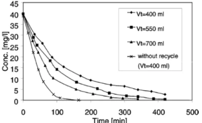
2at 4 bar and all membranes showed both a rejection and a ca- pacity to adsorb the pollutant with a transitory phase varying from 80 to 400 min at 4 bar. This behaviour could be a benefit for the process because oscillations in the pollutant concentration are not transmitted in the permeate. Three factors: rejection, photocatalytic degra- dation and adsorption were able to maintain the 4NP concentration in the permeate at very low values. For the continuous system, the lowest 4NP concentration in the permeate was 6-7% (w/w) of the initial 4NP con- centration (40 mg/L) after a transient period of 300 min. Further improvements of this process are under investigation[12].
Concerning membrane photoreactors various flow- sheet configurations were tested; the most interesting one was the continuous system presented in Fig. 6, where the catalyst is suspended in the aqueous solution and the irradiation is done on the recirculation reser- voir[12].
The optimum choice of the ratio between the irradi- ated volume and the total volume (V
i/V
t) was important. When total suspension volume was in-
creased from 400 to 700 mL (Fig. 7), the ratio V
i/V
tincreased owing to a constant recycle volume and, consequently, the 4NP abatement was higher due to the increased percentage of irradiated with respect to recycled suspension[12].
5. Integration of Photocatalysis with Mem- brane Processes for Purification of Water
The aim of the presented work was the investigation on the possibility of application of the hybrid photo- catalysis/membrane processes system for removal of azo dyes (Acid Red 18, Direct Green 99 and Acid Yellow 36) from water. The photocatalytic reactions were conducted in the flow reactor with immobilized photocatalyst bed and in the suspended system in- tegrated with ultrafiltration (UF). A commercially available titanium dioxide (Aeroxide P25, Degussa, Germany) was used as a photocatalyst. The solution after the photocatalytic reaction was applied as feed in nanofiltration (NF) or membrane distillation (MD). The changes of various parameters, including concentration of dyes, pH and conductivity of the solution, and TOC and TDS contents were analyzed during the process. It was found that the solutions containing the model azo dyes could be successfully decolorized during the pho- Fig. 6. Scheme of a continuous membrane photoreactor
system with suspended catalyst (A : oxygen reservoir; B : recirculation reservoir (reactor); C : thermostatting water;
D : UV lamp; E : manometer; F : flowmeter; G : mem- brane cell; H : magnetic stirrer; P : peristaltic pump; Sa : feed reservoir; Sp : permeate reservoir)[12].
Fig. 7. 4NP concentration in the retentate versus time vary-
ing the total volume of the recycle system in comparison
to the system without recycle. (T = 30°C, P = 3.5 bar,
[TiO
2] = 1 g/l, [O
2] = 22 ppm, I = 3.6 mW/cm
2, tangential
flowrate = 500 mL/min)[12].
tocatalytic processes applied in the studies. The appli- cation of UF process results in separation of photo- catalyst from the treated solutions whereas during the NF and MD high retention of degradation products was obtained[23].
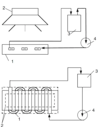
The experiments of the photocatalytic decomposition of dyes with application of the immobilized catalyst bed were conducted in the apparatus presented in Fig.
8. The main component of the system was the flow re- actor with immobilized catalyst bed. The reactor was built of quartz tubes partly covered with TiO
2particles.
The photocatalytic reaction in the suspended system was conducted in the photocatalytic membrane reactor utilizing UF where the catalyst particles were retained in the feed solution by means of the membrane. The apparatus applied in the photocatalysis/UF experiments is presented in Fig. 9.
As can be seen from Fig. 10, the AY36 dis- coloration required the longest time of irradiation,
which it took 30 h to obtain the complete color removal. For AR18 and DG99 the solutions were col- orless after 21 and 25 h, respectively. Although the light fastness is the lowest for DG99, the highest rate of discoloration was observed for AR18. Acid Red 18 is a monoazodye so it is more easily degradable than DG99 which has five azo bonds in the structure. From the other hand, AY36 which is a monoazodye, like- wise AR18, showed the lowest rate of discoloration.
However, AY36 has the highest light fastness equal to 7 (in the 8-grade scale) and this factor can explain the longest time required for discoloration of AY36 sol- ution[23].
Fig. 8. Schematic diagram of the reaction system with im- mobilized catalyst bed : (a) side view; (b) top view. 1.
quartz labyrinth flow reactor; 2. UV light source; 3. tank;
4. peristaltic pump[23].
Fig. 9. The apparatus applied in the photocatalysis/UF experiments. 1, membrane module; 2, pressure regulator;
3, stirrer; 4, feed tank; 5, suction pump; 6, pressure damp- er, 7, permeate tank[23].
Fig. 10. Changes in dyes concentration during the photo-
catalytic process (C
0: 10 mg/dm
3, solution volume, 4.5
dm
3)[23].
chemical oxidation photocatalysis process with physical separation via a ceramic membrane filtration was explored. The effects of operating parameters such as transmembrane pressure and the membrane pore size on the permeate flux and organic removal was investigated. The interaction between the two solutes in the system, humic acids and TiO
2photocatalyst, played an important role in the observed flux decline during ceramic ultrafiltration (UF) and microfiltration (MF).
Results showed that the MF membrane showed flux rates that were about 30% lower than the ones ach- ieved with UF membranes. The dissolved organic car- bon (DOC) removal was found to be higher in UF membrane (> 70%) compared to MF membrane (50%).
Finally from the liquid chromatography (LC) analysis showed that after photocatalytic treatment, there is a change in the molecular weight distribution of the or- ganic compounds and preferential adsorption of those compounds by TiO
2results in different fouling mecha- nisms in UF and MF membranes. It can be concluded that the use of ceramic membrane not only acts as a barrier in recovering the TiO
2photocatalyst but also assists in DOC reduction[24].
7. Effect of TiO
2Nanoparticles on Fouling Mitigation of Ultrafiltration Mem- branes for Activated Sludge Filtration
Membrane bioreactors (MBRs) have been widely used as advanced wastewater treatment process in re- cent years. However, MBR system has a membrane fouling problem, which makes the system less
competitive. Thus there have been great efforts for fouling mitigation. In this study, two types of TiO
2im- mobilized ultrafiltration membranes (TiO
2entrapped and deposited membranes) were prepared and applied to activated sludge filtration in order to evaluate their fouling mitigation effect. Membrane performances were changed by addition of TiO
2nanoparticles to the cast- ing solution. TiO
2entrapped membrane showed lower flux decline compared to that of neat polymeric membrane. Fouling mitigation effect increased with nanoparticle content, but it reached limit content above which fouling mitigation did not increase. Regardless of polymeric materials, membrane fouling was miti- gated by TiO
2immobilization. TiO
2deposited mem- brane showed greater fouling mitigation effect com- pared to that of TiO
2entrapped membrane, since larger amount of nanoparticle was located on membrane surface. It can be concluded that TiO
2immobilized membranes are simple and powerful alternative for fouling mitigation in MBR application[25].
Flux decline behavior was measured using membrane cell and surface area was 18.1 cm
2. Schematic diagram of the filtration system used in this study was shown in Fig. 11. Filtration tests were performed under the condition of 100 kPa at 20 ± 2°C. Crossflow velocity was controlled at 1.2 m/s and the flow rate was 2.5 L/min. Each set of experiment was performed simulta- neously at the same condition. Feed tank (reactor) was consistently aerated during the filtration test for oxygen supply to biomass. Flux decline was measured by
Fig. 11. Schematic diagram of crossflow activated sludge
filtration system[25].
weighing permeate on top-loading balance at timed in- tervals[25].
The results of activated sludge filtration tests were shown in Fig. 12. In this study, filtration test was per- formed at the condition of high flux and low crossflow velocity. Furthermore, the MLSS concentration of mixed liquor was high (7,000 mg/L). Thus flux decline progressed rapidly at the beginning of filtration for all membranes. The result clearly showed that fouling of TiO
2entrapped membrane was significantly reduced
compared to that of neat PSf membrane. It is well known that membrane fouling can be influenced by hydrodynamic condition, such as permeation drag and back transport, and chemical interaction between fou- lants and membranes. Since all the membranes were tested at the same hydrodynamic condition, the differ- ent fouling behavior means that surface property of membrane was changed by nanoparticle entrapment.
Surface of TiO
2entrapped membrane can be more hy- drophilic than that of neat polymeric membrane due to the higher affinity of metal oxides to water. Therefore, hydrophobic adsorption between sludge particle and TiO
2entrapped membrane was reduced, and deposited particles were readily removed by crossflow.
As shown in Fig. 11(b), with increase of TiO
2content in casting solution, fouling mitigation effect was gradu- ally improved until TiO
2/PSf ratio reached 0.3. However, beyond the ratio 0.3, flux decline behavior was not changed, although TiO
2content increased, as shown in Fig. 11(a). It means that surface property could not be improved beyond certain value. Furthermore, membrane performance and stability of casting solution can be poorer, since nanoparticles plug membrane pores and hinder the interaction between polymer and solvent molecules. Therefore, in case of TiO
2entrapped mem- brane, amount of TiO
2should be adjusted appropriately.
8. Hybrid Photocatalysis/Submerged Micro- filtration Membrane System for Drinking Water Treatment
In this study, the potential of UV/TiO
2photocatalytic oxidation method to control of membrane fouling caused by natural organic matter (NOM) was inves- tigated under various conditions in submerged MF membrane system. Effect of TiO
2concentration, UV ir- radiation in the absence of TiO
2, TiO
2in the absence of UV irradiation and combination of UV/TiO
2photo- catalytic oxidation were investigated. Additionally, in- termittent and continuous UV application and initial NOM concentration on the pressure increase and re-
(a)(b)
![Fig. 2. Kinetic of V-UV degradation of 2,4-DHBA with batch irradiation experiment[10].](https://thumb-ap.123doks.com/thumbv2/123dokinfo/5468756.439638/3.892.471.804.491.751/fig-kinetic-uv-degradation-dhba-batch-irradiation-experiment.webp)
![Fig. 5. Influence of UV illumination on fouling rates[11].](https://thumb-ap.123doks.com/thumbv2/123dokinfo/5468756.439638/4.892.86.424.141.547/fig-influence-uv-illumination-fouling-rates.webp)
![Fig. 11. Schematic diagram of crossflow activated sludge filtration system[25].](https://thumb-ap.123doks.com/thumbv2/123dokinfo/5468756.439638/7.892.470.802.147.346/fig-schematic-diagram-crossflow-activated-sludge-filtration.webp)

![Fig. 16. Effect of photocatalyst-coated PP beads on resist- resist-ance of membrane fouling in hybrid process of tubular ce-ramic MF and TiO 2 photocatalyst-coated PP beads[28].](https://thumb-ap.123doks.com/thumbv2/123dokinfo/5468756.439638/11.892.167.732.149.497/effect-photocatalyst-coated-membrane-fouling-process-tubular-photocatalyst.webp)
