한국정보통신학회논문지 Vol. 24, No. 9: 1165~1171, Sep. 2020
밀리미터파(mm-Wave) 대역 5G 이동통신 Array 안테나의 설계와 성능분석 연구
이성훈1*·이창교1·박재홍1·조수현1·최승호2·김태형2
Design and Performance Analysis of 5G Mobile Communication Array Antenna in Millimeter-Wave (mm-Wave) Band
Sung-hun Lee
1*· Chang-Kyo Lee
1· Jae-Hong Park
1· Soo-Hyun Cho
1· Seung-Ho Choi
2· Tae-Hyung Kim
21*
Senior researcher, Convergence Technology Research Division, Gumi Electronics & Information Technology Research Institute, Gyeongsanbuk-do Gumi, 39253 Korea
2
Managing director, Electronics Component R&D Center, LS Mtron Ltd, Anyang Gyeonggi-do, 14119 Korea
요 약
본 논문에서는 28 GHz와 38 GHz의5G 단말용 안테나 타입별 반사손실, 방사패턴 등의 성능을 고려하여 단일안테 나를 설계하고, 안테나 소자를 반 파장 간격으로 배열하여 5G 단말용 배열안테나를 설계하였고 성능을 분석하였다.
밀리미터파 대역 통신에서는 기존의 마이크로파 대역에서와는 달리 송수신 간의 높은 경로손실이 발생한다. 5G 밀 리미터파 단말용 배열안테나 설계에서는 안테나의 이득, 대역폭뿐만 아니라, 안테나 소자 간 격리도, side-lobe level(SLL) 등의 안테나 성능이 추가적으로 고려되어야 한다. 28GHz와 39GHz에서 제안하는 안테나 이득이 각각 약 13.5dBi 와 11.3dBi, 반사손실도 -18.4 dB과 -20 dB 이하의 측정 결과로부터 설계의 타당함을 입증하였고, 밀리미터 파 대역 응용으로서도 적합함을 보였다.
ABSTRACT
In this study, we designed a single antenna taking into account the performance, such as return loss and radiation pattern, of 28 GHz and 38 GHz array antennas for 5G mobile devices. In millimeter wave band communication, high path loss occurs between transmission and reception, unlike in conventional microwave bands. In the design of array antennas for 5G millimeter wave terminals, antenna performance such as antenna gain, bandwidth, isolation between antenna elements, side-lobe level(SLL), etc. should be further considered. The performance of the designed array antennas was analyzed by spacing the antenna elements at half a wavelength. Our results proved the validity of the design and its suitability for applications in mm-Wave by showing that the 28 GHz and 39 GHz array antennas had antenna gains of 13.5 dBi and 11.3 dBi and return losses below -18.4 dB and -20 dB, correspondingly.
키워드
: 밀리미터파, 배열 안테나, 28GHz 안테나, 5G 이동통신, 무선 통신시스템
Keywords
: Millimeter-Wave, Array, 28GHz antennas, 5G mobile, Wireless communication systems
Received 10 July 2020, Revised 20 July 2020, Accepted 27 July 2020
* Corresponding Author Sung-Hun Lee(E-mail:[email protected], Tel:+82-54-460-9036)
Senior researcher, Convergence Technology Research Division, Gumi Electronics & Information Technology Research Institute, Gyeongsanbuk-do Gumi, 39253 Korea
Open Access
http://doi.org/10.6109/jkiice.2020.24.9.1165
print ISSN: 2234-4772 online ISSN: 2288-4165Ⅰ. Introduction
The fifth generation (5G) mobile communication technology uses ultra-wideband not only to enable a fast data transfer rate, but also to have a high reliability for an ultra-low latency communication and massive machine- type communications. 5G technology aims at a technological evolution that is different from the existing 4G mobile communication technology. Unlike existing microwave or sub-6 GHz bands, 28 GHz and 39 GHz bands, which are anticipated to be the most widely used in the world, are prone to path loss during data transmission. In order to compensate for this loss, a high gain array antenna for the 5G mm-Wave band is used instead of the omnidirectional antenna used in 4G communications [1-3].
5G mobile communication, the next generation LTE- advanced technology, has a maximum transfer rate of 1 Gbps, which is 20 times faster than that of 4G mobile communication. While 4G uses a low frequency, below 2 GHz, 5G uses a high frequency of 28 GHz. The method of adding an antenna to a beamforming network has been used in a wide range of applications such as phased array, Rotman lens, and butler matrix [4-10].
Unlike the existing microwave band, the mm-Wave band communication is prone to high path loss during data transmission. In order to compensate for the loss, a high-gain array antenna of the 5G mm-Wave band is used instead of the omnidirectional antenna used in 4G communications.
When designing a 5G mm-Wave array antenna, in addition to antenna gain and bandwidth, properties such as the isolation between antenna elements and the side-lobe level must be considered. One of the most challenging tasks in such a design is securing a wide communication coverage. There are many researches focused on designing a 5G array antenna both in Korea and abroad [11].
In this study, we designed a single antenna taking into account the performance of 28 GHz and 38 GHz array antennas for 5G mobile devices such as return loss radiation pattern by type and analyzed their performance
by spacing the antenna elements at half a wavelength.
Ⅱ. ANTENNA DESIGN
Looking at the previous research on the 28 GHz band antenna, for the uplink/downlink communication between the base station and the mobile terminal, a 2×2 patch array antenna and 3D beam coverage that implement horizontal/vertical dual linear polarization through dual feeding to the patch antenna are provided. It is a combination of 1×2 and 2×1 dipole array antennas [12].
Since the propagation path loss in free space is inversely proportional to the square of the wavelength, the propagation path loss in the mmWave band is larger than that of the existing cellular band. In order to overcome the high propagation path loss in the mmWave band and use it for mobile communication applications, antenna array technology and beamforming technology that collect energy in an optimal path between transmitting and receiving terminals are essential. However, in the millimeter wave environment, when the polarizations of the transmitting and receiving terminals do not match, a problem that the received signal strength is reduced by about 5 to 10 dB may occur. In addition, in the case of using the millimeter wave band in an indoor communication environment, using circular polarization rather than linear polarization is more effective in reducing delay spread due to multipath propagation [13]. Therefore, as a solution to this problem, a millimeter wave band antenna using a circularly polarized antenna has been proposed [14]. As such, research on antenna design for 5G terminals has been actively conducted at home and abroad, but research on array antennas considering both linear and circular polarization is incomplete.
2.1. 28 GHz and 38 GHz 5G single antenna design
In order to develop a patch type antenna applicable to
the 28 GHz mm-Wave 5G mobile communication system,
we used RO4350B, which is a hydrocarbon ceramic
laminate from Rogers, and RT/duriod 588, which is a
glass microfiber reinforced PTFE laminate widely used for processing PCBs in the mm-Wave band.
In the design of the 28 GHz microstrip patch antenna, we selected a substrate with a low thickness that is mainly used for the mm-Wave band and a line width of 50 ohm lines for the patch array antenna design.
Thereafter, we performed line calibration for the transformer impedance. Fig.1 shows a basic single antenna structure for a 28 GHz 5G array antenna with 50 ohm lines whose width and length are 0.54 mm and 1.57 mm, respectively, and a transformer whose length and line width are 1.53 mm and 0.93 mm, respectively
Fig. 1 28 GHz mm-Wave Single patch antenna design
Based on the structures proposed in recently published designs for 5G array antenna, a dipole antenna was designed with its substrate having feed lines, one pole on the top surface and ground, and the other pole on the bottom surface [15]. It was designed to have patches on the top surface and ground on the bottom surface as in commonly used inset feed microstrip patch antennas.
Fig. 2 shows a basic single antenna structure for a 39 GHz 5G array antenna with 50 ohm lines whose width and length are 0.55 mm and 1.12 mm, respectively, and a transformer whose length and line width are 1.09 mm and 1.09 mm, respectively.
Fig. 2 39 GHz mm-Wave single patch antenna design
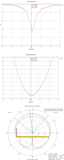
Fig. 3 shows the far field radiation pattern of the mm-Wave 28 GHz single antenna. The antenna gain was
approximately 6.199 dBi. The return loss was below -15.3 dB at the target frequency of 28 GHz.
Fig. 3 28 GHz mm-Wave single patch antenna design results
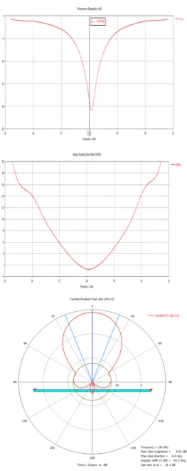
Fig. 4 shows the far field radiation pattern of the
mm-Wave 39 GHz single antenna. The antenna gain was
approximately 7.797 dBi. The return loss was below
-20.9 dB at the target frequency of 39 GHz.
Fig. 4 39 GHz mm-Wave Single patch antenna design results
2.2. 28 GHz and 38 GHz 5G array antenna designs Fig. 5 and 6 show the mm-Wave 5G array antennas with four antennas designed into the single antenna design stage and arranged at the intervals of 0.5 λ. Each structure, substrate, and variables are the same as those of the single antenna shown in Fig. 1 and 2. The size of
the substrate was 25 mm × 25 mm × 0.05 mm based on the size of the mm-Wave 5G mobile device. The array antenna was placed on top of the substrate.
Fig. 5 28 GHz mm-Wave 8 array antenna design
As for the patch antenna, the top edge of its substrate was designed to fold 90° in +z direction for maximum radiation [16].
Fig. 6 39 GHz mm-Wave 8 array antenna design
To test the performance of the array antenna, we made a prototype that includes a feed line
Ⅲ. EXPERIMENTAL RESULTS
Tables 1 and 2 show the results of design and performance analyses of the mm-Wave 28 GHz and 39 GHz array antennas.
For the 28 GHz array antenna, the antenna gain was 13.5 dBi, the return loss was below -18.4 dB, and the return loss bandwidth was 1 GHz, which are similar to the simulation values.
Table. 1 28 GHz mm-Wave 2 x 4 patch antenna designs and performance results
Performance Measures Design Observed Center Frequency 28 GHz 27.2-28.2 GHz Frequency Bandwidth
(VSWR<2) 1 GHz 1 GHz
Return Loss -17.9 dB -18.4 dB
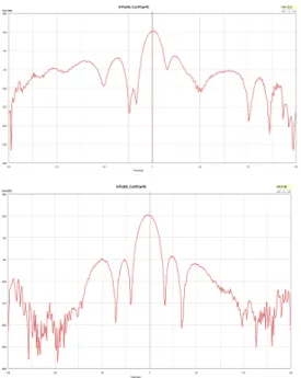
Fig. 7 show the maximum gain at φ=0° and θ=90°
when looking at the measurement results, 13.5 dBi.
Fig. 7 2x4 patch antenna E/H-plane 2D measurement results @28GHz
For the 39 GHz array antenna, the antenna gain was 11.3 dBi, the return loss was below -20 dB, and the return loss bandwidth was 1 GHz, which are similar to the simulation values.
Table. 2 39 GHz mm-Wave 2 x 4 patch antenna designs and performance results
Fig. 8 show the maximum gain at φ=0° and θ=90°
when looking at the measurement results, 11.3 dBi.
Fig. 8 2X4 patch anenna E/H-plane 2D measurement results @39GHz
Ⅳ. CONCLUSION
In this paper, we designed an array antenna that operates in the 28 GHz and 39 GHz bands for 5G mobile communication to enable data transfer in GB and tested its validity by building a prototype and measuring its radiation patterns.
Our results prove the validity of the design and its suitability for application in the mm-Wave band. The 28 GHz and 39 GHz array antennas had the antenna gains of 13.5 dBi and 11.3 dBi and return losses below -18.4 dB and -20 dB, correspondingly. Due to its excellent
Performance Measures Design ObservedVSWR 1.29 1.25
Radiation Gain 15.01 dBi 13.5 dBi Patch Element Size
(X × Y × Z)
3.44 × 2.55 × 7.49 mm3
3.44 × 2.55 × 7.49 mm3 Antenna Size 29 × 14 mm2 29 × 14 mm2
Performance Measures Design Observed Center Frequency 39 GHz 38.4-39.4 GHz Frequency Bandwidth
(RL = -12 dB) 1 GHz 1 GHz
Return Loss -13.3 dB -20 dB
VSWR 1.54 1.1
Performance Measures Design Observed Radiation Gain 13.5 dBi 11.3 dBi Patch Element Size
(X × Y × Z)
2.47 × 1.76 × 5.38 mm3
2.47 × 1.76×
5.38 mm3
Back side Size 21 × 10 × 0.254 mm3
21 × 10 × 0.254 mm3
properties, we expect it to be used in a wide range of mm-Wave wireless communication applications.
ACKNOWLEDGEMENT
This work was supported by the Institute of Information & Communications Technology Planning
& Evaluation (IITP) grant funded by the Korean government (MSIT) [2019-0-00068, Development of Millimeter Wave 5G Components Using Compound Semiconductor Process] and Autonomous car key technology development projects by KEIT and MOTIE [10080063, Development of Hybrid V2X Communication Module for Autonomous Driving]
References
[ 1 ] H. Xia, T. Zhang, L. Li, and F. Zheng, “A low-cost dual-polarized 28 GHz phased array antenna for 5G communications,” in 2018 International Workshop on Antenna Technology(iWAT), Nanjing, pp. 1-4, Jun. 2018.
[ 2 ] N. Ojaroudiparchin, M. Shen, and G. F. Pedersen, “Design of Vivaldi antenna array with end-fire beam steering function for 5G mobile terminals,” in 2015 23rd Telecommunications Forum Telfor(TELFOR), Belgrade, pp. 587-590, Nov. 2015.
[ 3 ] M. Bansal, L. Shricastava, “Performance Analysis of Wireless Mobile Adhoc Network with Different Types of Antennas,” Asia-pacific Journal of Convergent Research Interchange, vol.3, no.1, pp. 29-39, Mar. 2017.
[ 4 ] K. Araki, A. Tanaka and E. Matsumura, “Wide scanning phased array antenna design in Ka band,” IEE Proc.-Microw.
Antennas Propagation, vol. 150, no. 5, pp. 379-384, Oct.
2003.
[ 5 ] Y. H. Peng and L. H. Lu, “A Ku-band frequency synthesizer in 0.18-um CMOS technology,” IEEE Microwave and Wireless Components Letters, vol. 17, no. 4, pp. 256-258, Apr. 2007.
[ 6 ] Z. Qiu and P. Zong, “Three-dimensional phased array antenna analysis and simulation,” in 2009 3rd IEEE International Symposium on Microwave, Antenna, Propagation and EMC Technologies for Wireless Communications, pp.538-542, Oct. 2009.
[ 7 ] T. C. Cheston and J. Frank, Phased Array Radar Antennas, in Radar Handbook, New York, NY: McGraw-Hill, 1990.
[ 8 ] S. Jeong and T. W. Kim, “Design and Analysis of Swapped Port Coupler and Its Application in a Miniaturized Butler Matrix,” IEEE Transactions on Microwave Theory and Techniques, vol. 58, no. 4, pp. 764-770, Apr. 2010.
[ 9 ] W. Rotman and R. F. Turner “Wide-angle microwave lens for line source applications,” IEEE Trans. Antennas Propag., vol. 11, no. 6, pp. 623-632, Nov. 1963.
[10] C. H. Tseng, C. J. Chen and T. H. Chu, “A Low-Cost 60-GHz Switched-Beam Patch Antenna Array With Butler Matrix Network,” in IEEE Antennas and Wireless Propagation Letters, vol. 7, pp. 432-435, Jul. 2008.
[11] K. Zhao, J. Helander, D. Sjoberg, S. He, T. Bolin, and Z.
Ying, “User body effect on phased array in user equipment for the 5G mm-Wave communication system,” IEEE Antennas and Wireless Propagation Letters, vol. 16, pp.
864-867, Sep. 2016.
[12] Y. J. Kim, J. Maharjan, D. Y. Choi, “Rectangular Miccrostrip Patch Antenna with Semicircular Structure for 5G Applications,” Journal of the Korea Institute of Information and Communication Engineering, vol. 23, no. 10, pp. 1269- 1274, Oct. 2019.
[13] T. Manabe, Y. Miura, and T. Ihara, “Effects of antenna directivity and polarization on indoor multipath propagation characteristics at 60 GHz,” IEEE Journal on Selected Areas in Communications, vol. 14, no. 3, pp. 441-448, Apr. 1996.
[14] I. Syrytsin, S. Zhang, G. F. Pedersen, and Z. Ying, “User effects on the circular polarization of 5G mobile terminal antennas,” IEEE Transactions on Antennas and Propagation, vol. 66. no. 9, pp. 4906-4911, Sep. 2018.
[15] N. O. Parchin, M. Shen, and G. F. Pedersen, “UWB Mm-Wave antenna array with quasi omnidirectional beams for 5G handheld devices,” in 2016 IEEE International Conference on Ubiquitous Wireless Broadband (ICUWB), Nanjing, pp. 1-4, 2016.
[16] M. Stanley, Y. Huang, H. Wang, H. Zhou, A. Alieldin, and S. Joseph, “A capacitive coupled patch antenna array with high gain and wide coverage for 5G smartphone applications,”
IEEE Access, vol. 6, pp. 41942-41954, Aug. 2018.
이성훈(Sung-Hun Lee)
구미전자정보기술원 선임연구원 광운대학교 컴퓨터공학과 공학박사 광운대학교 전파공학과 공학석사
※관심분야 : 무선통신네트워크, Cross-layer network design
이창교(Chang-Kyo Lee)
구미전자정보기술원 선임연구원 금오공과대학교 모바일공학과 공학석사
※관심분야 : 이동통신 네트워크, 전기전자
박재홍(Jae-Hong Park)
구미전자정보기술원 선임연구원 충남대학교 전파공학과 공학석사
※관심분야 : 이동통신 네트워크, 전기전자
조수현(Soo-Hyun Cho)
구미전자정보기술원 센터장(책임연구원) 금오공과대학교 컴퓨터공학과 공학박사 금오공과대학교 컴퓨터공학과 공학석사
※관심분야 : 무선통신기술, 네트워크 보안
최승호(Seung-Ho Choi)
LS엠트론 책임연구원
연세대학교 전파통신공학 공학석사
※관심분야 : 이동통신 안테나, mmWave network, RF
김태형(Tae-Hyung Kim)
LS 엠트론 선임연구원
광운대학학교 전파공학과 공학석사
※관심분야 : 무선통신기술, 전기전자, RF