http://dx.doi.org/10.7839/ksfc.2014.11.1.001
다수의 가동물체형 파력발전기에 있어서의 2차측 제어 정유압변속기 응용 Application of Secondary Control Hydrostatic Transmission in
A Multi-Point Absorbing Wave Energy Converter
도황팅
1․안경관
2*H. T. Do and K. K. Ahn
Received: 7 Jan. 2014, Revised: 25 Feb. 2014, Accepted: 25 Feb. 2014
Key Words:Hydrostatic Transmission (정유압 변속기), Pressure Coupling (압력커플링), Turbine (터빈), Wind
Energy Conversion System (풍력에너지 변환시스템)
Abstract: This paper presents a novel concept of wave energy converter for electric generation from the ocean
wave energy. In this paper, a Multi-Point Absorbing Wave Energy Converter, shortened as MPAWEC by using Secondary Control Hydrostatic Transmission (SCHST) was proposed. The power take-off (PTO) system in the proposed MPAWEC includes multi heaving buoys to drive hydraulic pumps placed at different points. The application of SCHST in MPAWEC gives some advantages, such as longevity of hydraulic components; more energy is harvested; the variation of the pressure in the accumulator limited; therefore the accumulator volume is reduced and the output speed is more stable, etc. A PID controller was designed for speed control of the hydraulic motor. The simulation results indicated that the speed of the generator was ensured with the relative error as 0.67%; the efficiency of the proposed system was 71.4%.
* Corresponding author: [email protected]
1 School of Mechanical Engineering, University of Ulsan, Ulsan, Korea.
2 School of Materials Science and Engineering, University of Ulsan, Ulsan, Korea.
Copyright Ⓒ 2014, KSFC
This is an Open-Access article distributed under the terms of the Creative Commons Attribution Non-Commercial License(http://
creativecommons.org/licenses/by-nc/3.0) which permits unrestricted non-commercial use, distribution, and reproduction in any medium, provided the original work is properly cited.
1. Introduction
Renewable energy has become more and more important resource in the recent years, especially since Fukushima nuclear disaster. To replace the fossil energy, wave energy can be a good option because of its majority, clean and endlessness.
There are many different types of wave energy converters currently being developed, such as:
Overtopping Devices (Wave Dragon), Attenuators (Pelamis), Terminator Devices (Oscillating water
column), Point absorbers (WaveBob, OPT PowerBuoy), etc., 1). Among them, heaving point absorbers are one of the simplest and most promising concepts, due to their ease of installation and deployment in large arrays.
Comparing to other technologies, point absorbers
could potentially provide a large amount of power
in a relatively small device, and, they are relatively
small compared to wave length. Although there
are many different designs and strategies for
deploying these types of WEC, they can be divided
into two major categories: (i) wave energy is
converted to electric energy by a mechanical
transmission, such as gearbox, ratchet-wheel,
rack-pinion… 2); (ii) wave energy is converted to
electric energy by a hydrostatic transmission, such
as hydraulic pump, motor cylinder… 3). The
generators in both these manners are driven by
fluctuating speed due to the fluctuation of wave
and the change of climate. The output power is
therefore variable. The electric energy from the generator is stored in batteries and transferred to electric grid by a proper electric circuit. The frequent variation of charging power from generator reduces the longevity of batteries and other components in the electric circuit. Otherwise, in case wave power exceeds the absorption power of the electric system, the redundant power will be cut by mechanical or electrical method to prevent the system from overpower. This limits the generating ability of the system and reduces the generated electric energy.
There are some researches were proposed for predicting wave condition by Vantorre in 4), or by Asina in 5), optimizing the extracted energy from the waves by Margheritini in 6), Santana in 7), wave power extraction algorithm such as phase control or de-clutching control by Falco in 8) and Babarit 9), and so on. However, these approaches remain some disadvantages. Firstly, the generated power is still much affected by the variation of wave power. Secondly, in order to protect the electric system from overpower, the cutout power still exist and is not recovered. Thirdly, in case of low input power of wave, the generated power is decreased.
In addition, there are two reasons that the driven speed need to be constant. First of all, due to recommendation of manufactures, generators should be driven in rated speed or within a predefined speed difference, otherwise the generated electric power will be low or the generator will be damaged. Secondly, there are some special types of generators which can adapt to low and variable driven speed. However, they are high-cost and the output power is still affected by the variation of driven speed.
To overcome these drawbacks, this paper proposed a multi-point absorber for wave energy converter (MPAWEC) by using Secondary Control Hydrostatic Transmission (SCHST). This combination makes many benefits:
- A SCHST with hydraulic accumulator can not only inherit the advantages of HST but also
recover the redundant power for reusing as low input power and smoothen the pressure in high pressure fluid supplied to the hydraulic motor. By adding the high-pressure accumulator, the operation principle of HST changes from flow coupling to pressure coupling 10) and becomes more efficient.
- In the proposed MPAWEC, each point is placed at different phase from other points, so that they can compensate together and reduce the variation amplitude of the pressure in the accumulator.
- The driven generator speed is relative constant whatever the wave power changes.
A PID controller was designed to control output speed of the generator in constant speed. The efficiency of the proposed system was verified by simulation using AMESim software.
The remains of this paper are organized as follow: section 2 describes the proposed MPAWEC operation principle; section 3 explains the mathematical model of hydraulic system; section 4 shows the simulations and analysis of the simulation results. Finally, conclusion is presented in section 5.
2. Description of SCHST-WECS
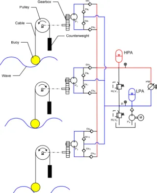
The hydraulic circuit of the proposed MPAWEC is shown in Figure 1. The proposed MPAWEC in this paper includes three heaving buoys. Each heaving buoy is placed at 1200 different phase from neighboring buoys on wave propagation circle. The buoys are supported by frames. Each buoy and counterweight is connected via a cable to twin a pulley. Because of oscillation of wave surface, buoys are moved up-and-down. In buoy moving up, the pulley is rotated by heaviness of counterweight. In buoy moving down, it is rotated by heaviness difference of buoy and counterweight.
The torque pulley rotation should be equal in these two cases; therefore, the mass of a buoy is twice heavier than a counterweight. The pulleys are speed up by gearboxes to drive hydraulic pumps.
The hydraulic circuit was designed properly with
check valves that high pressure fluid from two ports of the pumps always enters into the hydraulic accumulator HPA but blocking the reverse direction. The high pressure fluid in the accumulator is used to drive the hydraulic motor PM. Speed of the hydraulic motor is controlled by a simple PID controller. The output shaft of the hydraulic motor PM is coaxially connected to the generator G via a clutch, which coupled if the speed is in acceptable range and decoupled as overspeed. The relief valve RLV
1releases the high pressure in the accumulator HPA to protect the hydraulic circuit as the pressure becomes too high.
The boost system includes a boost pump P
b, a low pressure accumulator LPA and a relief valve RLV
2. The low pressure accumulator LPA functions as a fluid tank, the boost pump maintains the low pressure in LPA and the relief valve RLV
2protects the boost system from overpressure.
Fig. 1 Hydraulic circuit of SCHST- MPAWEC
3. Mathematical Modeling of SCHST-WECS
3.1 Model of hydraulic pump
The ideal flow rates, volumetric and mechanical
efficiencies of the piston hydraulic pump are expressed in eq. (1), (2) and (3), respectively:
max
Q
i= αω D (1)
( )
/vP Qi Ql Qi
η
= −(2)
(
max) (
/ max)
tP D p D p Tl
η
=α
Δα
Δ +(3)
The actual output flow rate and input torque of the pump are expressed in eq. (4) and (5), respectively:
o i pV
Q Q = η (4)
max
i tPM
T = Δ α pD η (5) where Q
i, Q
land T
lare the ideal flow rate, loss flow rate and loss torque of the pump, respectively and were discussed in 11)-13); α , D
max, Δ p are displacement ratio, maximum displacement and pressure difference between two ports of the pump, respectively.
3.2 Model of hydraulic motor
The volumetric efficiency, mechanical efficiency, actual flow rate and actual output torque of the piston hydraulic motor are expressed by eq. (6) - (9), respectively.
( )
max
/
maxvM
D D Q
lossη = α ω α ω + (6)
(
max) (
/ max)
tM D p Tloss D p
η
=α
Δ −α
Δ(7)
m i/ vM
Q =Q
η (8)
max
m tM
T = Δ α pD η (9)
3.3 Electro-hydraulic displacement control mechanism (DCM)
An electro-hydraulic mechanism regulates the
angle of the swash plate for control the
displacement of the hydraulic machine. The full
order model of the system is a fifth-order system
with voltage input and the angle of the swash plate
or the displacement of the hydraulic machine.
However, in practical application of hydraulic systems, a reduced first-order model is often used instead of the full order model 14)-15). In this study, a first-order model of the electro-hydraulic mechanism is used and expressed the below equation:
( )
/ sv / svu t =
τα
& K +α
K(10)
where u(t)istheelectricsignalcontrol,t is the time constant, and K
svistheDCgainoftheDCM.
3.4 Model and calculation of hydraulic accumulator
0 0 max min
n n n
pV = p V = p V (11) Then the fluid volume in the hydraulic accumulator HPA is derived as:
( )
0 1/
0 0
0,
1 / ,
i
f n
i
if p p
V V p p else
⎧⎪ ≤
= ⎨ ⎪⎩ − (12)
where V
0is the volume of hydraulic accumulator,
p0is pre-charged pressure, p
iis pressure at the port of hydraulic accumulator and n is adiabatic coefficient.
The energy that can be absorbed by HPA is calculated as:
1/ ( 1)/ ( 1)/
0 0n maxn n 0n n
/ ( 1)
E V p = ⎡ ⎣ p
−− p
−⎤ ⎦ n − (13)
here, p
maxis maximum operation pressure of HPA.
The optimal pre-charged pressure for maximum energy capacity of HPA is given by:
/( 1)
0 max
p = n
−n n−p (14) And the maximum energy stored in HPA is given by:
/( 1)
max max 0
/
n nE = p V n
−(15)
Then the volume of HPA is derived as:
/( 1)
0 w,max n n
/
maxV = E n
−p (16)
where
Ew,maxis the maximum wave energy in one cycle.
3.5 Model of connecting line
The pressure at the output port of each pump is defined as:
( ) / , 1, 2,3.
pi
poi cvi h
dp Q Q V i
dt = − β = (17)
where
βis fluid bulk modulus, V
his volume of hoses,
Qpo1, Qpo2 and Qpo3
are output flow rate of the pump P
1,P
2and P
3, respectively, expressed by:
poi pi max l
Q = ω D α − Q (18)
Qcv1, Qcv2 and Qcv3are flow rate of the check valve CV
1,CV
2and CV
3, respectively. Neglecting the leakage, the flow rate of these check valves is expressed as:
2 / ,
1, 2,3 0,
d cvi pi h pi h
cvi
C A p p if p p
Q i
else
⎧ − ρ ≥
=⎪⎨ =
⎪⎩
(19)
Acv1
, A
cv2, A
cv3are check valve throttling area of the check valve CV
1,CV
2and CV
3, respectively.
Cd
is discharge coefficient.
The pressure in high pressure line p
his expressed as:
(
1 2 3) /
h
cv cv cv ha r pm h
dp Q Q Q Q Q Q V
dt
= + + − − −
β(20)
Qha
is the flow rate into HPA, from eq. (12), Q
hawas calculated as:
( )
0 1/
0 0
0,
1 / ,
i ha n
i
if p p
Q d else
V p p
dx
≤
⎧⎪
= ⎨⎪⎩ ⎡⎣ − ⎤⎦
(21)
Qpi
is the actual flow rate into the inlet port of the pump expressed in eq. (4).
Qr
is the flow rates via the relief valves RLV
1, according to 17), it is expressed by:
0,
2 / ,
set r
d v set
if p p
Q C A p ρ if p p
⎧⎪ Δ ≤
= ⎨ ⎪⎩ Δ Δ ≥ (23)
where
Av
is valve-throttling area, m
2pset
is the setting pressure of the relief valve.
Qpm
is the actual flow rate of the hydraulic motor PM as in eq. (8).
Δp is pressure difference of high-pressure line
and low-pressure line.
h l
p p p
Δ = − (24) where plisthe returning line pressure, which is considered as the pressure in LPA.
3.6 Model of load
The generator causes load on motor PM. The dynamic equation of the load is obtained by applying Newton’s second law, as:
m r
T = J ω & + C ω + T (25) where, T
mis the torque generated by the hydraulic motor, presented in eq. (9); J, C and
ωare inertial moment, viscous friction coefficient and the speed of the generator, respectively; T
ris the rated torque to create the electric current.
3.7 Control of Multi-Point Absorbing Wave Energy Converter
A PID controller was employed to control the speed of the hydraulic motor M.
M
K e K edt K e
p i dα = + ∫ + & (26)
r M
e = ω ω − (27)
Where, e is the speed error of the reference speed ωr and motor speed ωM. The coefficients
Kp, K
i and K
d are called as PID gains. K
p, K
i and
Kd were chosen with criteria of small error, small overshoot and fast response by try and error method.
. The coefficients
Kp, K
iand K
dare called as PID gains. K
p, K
iand
Kdwere chosen with criteria of small error, small overshoot and fast response by try and error method.
4. Simulation
Based on the parameters of the generator and
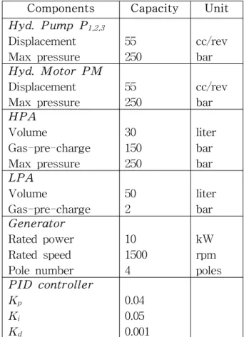
wave condition, hydraulic components of the proposed system could be calculated and chosen as shown in Table 1.
In simulation, floating buoy motion has sinusoidal form. Pumps speeds are shown in Figure 3. The output flow of each pump is rectified by check valves, but the flow rate amplitude is still large. By combination of 3 pumps, the total flow rates have smaller amplitude.
Table 1 Setting parameters of the system
Components Capacity Unit
Hyd. Pump P1,2,3
Displacement Max pressure
55 250
cc/rev bar
Hyd. Motor PMDisplacement Max pressure
55 250
cc/rev bar
HPAVolume
Gas-pre-charge Max pressure
30 150 250
liter bar bar
LPAVolume
Gas-pre-charge
50 2
liter bar
GeneratorRated power Rated speed Pole number
10 1500 4
kW rpm poles
PID controllerKp
Ki
Kd
0.04 0.05 0.001
Figure 4 demonstrates the speed response of the hydraulic motor. The reference speed is changed depending on the pressure of the hydraulic accumulator HPA, as shown in Figure 5. If the pressure reaches the high level- 210bar, then the reference speed is switched to the rate speed of generator- 1500rpm. If the pressure decreases to the low level- 160bar, then the reference speed is switched to zero for accumulating energy. The speed response error, about 10rpm or relative speed error is 0.67%.
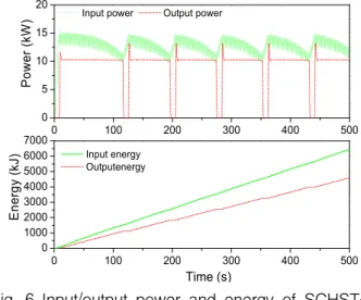
Figure 6 shows the input/output power and
energy of the proposed system. The input power is fluctuating. Thanks to the accumulator HPA, and PID controller, the output power is nearly constant.
At the end of simulation, the Input energy is 6429.7kJ and output energy is 4591.2kJ. The efficiency of the proposed system is 71.4%.
0 20 40 60 80 100
100 2030 4050 6070
0 20 40 60 80 100
-400 -200 0 200 400
0 20 40 60 80 100
-400 -200 0 200 400
3 pumps 1 pump
Pumps flow rate (Lpm)
Pump 1 Pump 2 Pump 3
Speed of 3 pumps (rpm)Speed of 1 pump (rpm)
Fig. 3 Pump speed and pump flow rate of the first and the second simulation
Reference Response
0 100 200 300 400 500
0 250 500 750 1000 1250 1500 1750
0 100 200 300 400 500
-150 -100 -50 0 50 100 150
Speed rpm
Time (s)
Speed error rpm
Fig. 4 Speed response of the hydraulic motor in the first and the second simulation
0 100 200 300 400 500
160 170 180 190 200 210 220
0 100 200 300 400 500
-10 -5 0 5 10
HPA pressure (bar)
Time (s)
RLV flow rate (Lpm)
Fig. 5 Pressure of the hydraulic accumulator HPA and flow rate of the relief valve RLV
10 100 200 300 400 500
0 5 10 15 20
0 100 200 300 400 500
0 1000 2000 3000 4000 5000 6000 7000
Input power Output power
Power (kW)
Input energy Outputenergy
Time (s)
Energy (kJ)