• 검색 결과가 없습니다.

Development of the Flexible Observation System for a Virtual Reality Excavator Using the Head Tracking System

N/A
N/A
Protected

Academic year: 2021

Share "Development of the Flexible Observation System for a Virtual Reality Excavator Using the Head Tracking System"

Copied!
7
0
0

로드 중.... (전체 텍스트 보기)

전체 글

(1)

http://dx.doi.org/10.7839/ksfc.2015.12.2.027

Development of the Flexible Observation System for a Virtual Reality Excavator Using the Head Tracking System

헤드 트래킹 시스템을 이용한 가상 굴삭기의 편의 관측 시스템 개발

Q. H. Le1, Y. M. Jeong1, C. T. Nguyen1 and S. Y. Yang2* 레광환․정영만․웬치탄․양순용

Received: 23 Mar. 2015, Revised: 13 Apr. 2015, Accepted: 20 Apr. 2015

Key Words:Head Mounted Display(헤드 마운트 디스플레이), Inertial Measurement Unit (관성 측정 장치), Virtual Reality (가상 현실), Excavator (굴삭기), Head tracking (헤드 트레킹)

Abstract: Excavators are versatile earthmoving equipment that are used in civil engineering, hydraulic engineering, grading and landscaping, pipeline construction and mining. Effective operator training is essential to ensure safe and efficient operating of the machine. The virtual reality excavator based on simulation using conventional large size monitors is limited by the inability to provide a realistic real world training experience.

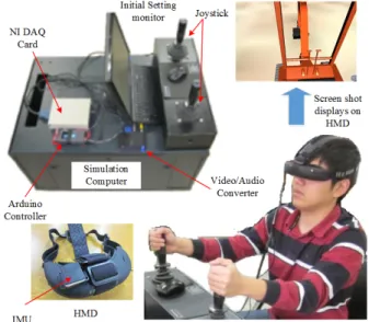
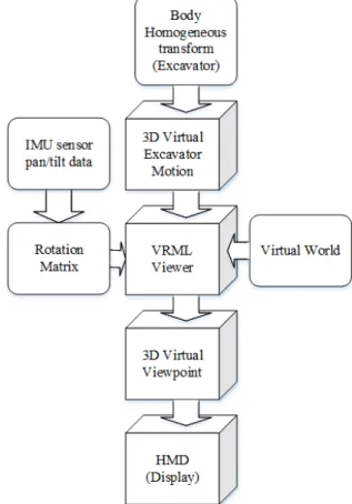
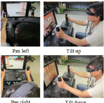
We proposed a flexible observation method with a head tracking system to improve user feeling and sensation when operating a virtual reality excavator. First, an excavation simulator is designed by combining an excavator SimMechanics model and the virtual world. Second, a head mounted display (HMD) device is presented to replace the cumbersome large screens. Moreover, an Inertial Measurement Unit (IMU) sensor is mounted to the HMD for tracking the movement of the operator's head. These signals consequently change the virtual viewpoint of the virtual reality excavator. Simulation results were used to analyze the performance of the proposed system.

* Corresponding author: [email protected]

1 Department of Mechanical and Automotive Engineering, University of Ulsan, Ulsan, 680-749, Korea

2 S. Y. Yang: School of Mechanical Engineering, University of Ulsan, Korea, 680-749, Korea

Copyright Ⓒ 2015, KSFC

This is an Open-Access article distributed under the terms of the Creative Commons Attribution Non-Commercial License(http://

creativecommons.org/licenses/by-nc/3.0) which permits unrestricted non-commercial use, distribution, and reproduction in any medium, provided the original work is properly cited.

1. Introduction

Excavators are typical hydraulic heavy-duty human-operated machines used in general versatile construction operations, such as digging, carrying loads, grounding and dumping loads.

1-2)

However, operating excavators on the risk surroundings is not safe for human to control on site.

3-4)

Thus, hydraulic excavator operators must be adequately

trained to develop the skills sets needed to ensure

a safe, effective and efficient operation of the

equipment. The training methods for excavator

operator have historically been based on the on-site

and off-site instruction which requires significant

cost and time commitments. Recent advances in

software and computer processing capabilities have

fostered the development of virtual reality (VR)

simulators as a low cost alternative to on-site

operator training. The use of virtual reality

simulators have been explored as a training vehicle

in a variety of research and industrial

applications.

5-11)

In VR excavator, users often

observe the motion of the machine through many

large-size monitors which limit the field of view

and realistic training experience. This paper will

present an observation system for VR excavator

using head tracking system. First, a simulation of

(2)

excavator which is designed and conducted by combining the SimMechanisc model and Virtual Reality Modeling Language (VRML) is able to interact with a virtual world. Second, the cumbrous screens are replaced by a light weight head mounted display device (HMD) to preform the images of the VR excavator. An IMU sensor is mounted to HMD for tracking the angular rotation of the head of operator. These values are transferred to the simulator and force the direction of 3D virtual viewpoint to follow the movement of operator's head. Thus, the proposed system provides more realistic training experience and space sensation for user when operating the VR excavator. For testing the performance of the system, a digging work is conducted to analyse the efficiency and intuitiveness of the proposed method.

Fig. 1 Diagram of four main modules for the flexible observation system

2. Architecture of the system

In this study, a flexible observation system was developed for the VR excavator. The system consists of four main modules as input module, communication module, simulation module and display module. The diagram of these modules is presented in Fig. 1 and the overview of the real system is shown in Fig. 2.

In the input module, the joysticks are used to operate the movement of the excavator. The IMU sensor is mounted to HMD for tracking rotational angle of an user's head. These input signals are connected to the communication module to transfer the command data for the simulation module. In communication module, Arduino Mega converts the IMU sensor data to analog signals. Then, these analog signals from Arduino Mega and joystick are transferred to the computer via DAQ NI PCI-6030 card. The excavator simulation module consists of SimMechanics model and a 3D graphics model of excavator. The SimMechanics model simulated the dynamics system from the input of the joysticks.

Meanwhile, the 3D graphics can maintain the 3D motion of the excavator in virtual reality environment so that the user can observe the operation of the machine. As usual, the user can track the system status by viewing the large monitors. Each monitor presents a different viewpoint which relates the view direction of the user. Thus, this requires at least three monitors to display the front side, left side and right side of viewing for user when operating the excavator.

This structure makes the system large, cumbrous and expensive. In this paper, a Head Mounted Display (HMD) is used to replaced the conventional monitors of the display module. Besides, the head tracking system is applied to change the direction view intuitively and conveniently.

Fig. 2 The overview of the flexible observation

system for VR excavator

(3)

3. Simulation of excavator

In this study, a VR Excavator is designed based on the real parameters of the 1.5 ton hydraulic excavator. The excavator simulation is modeled by using the Data Aquisition toolbox, Simcapse toolbox and Simulink 3D Animation toolbox of Matlab/Simulink software. Following the Fig. 3, the diagram of excavator simulation consists of four main subsystems as Joystick subsystem, IMU sensor subsystem, Excavator SimMechanics model subsystem and VR Excavator subsystem. The Joystick subsystem and IMU sensor subsystem are configured to access the data acquisition hardware (NI PCI 6030) and read the data into the simulation. Therefore, the input signals from joystick and IMU sensor are able to connect the excavator simulation via this interface.

Fig. 3 The diagram of excavator simulation

Fig. 4 Excavator SimMechanics model

3.1 Excavator SimMechanics model

The dynamics modeling of excavator is designed by using SimMechanics model which is shown in Fig. 4. In this model, the actuator status of boom, arm, bucket and base are input parameters which are controlled by user. Besides, the mass, inertia and 3D geometry of the real excavator are imported to the dynamics equations. Then, the status of each body and joint of excavator are tracked and transferred to Body Homogeneous Transform (BMT).

It can be seen that the motion of the excavator is simulated via the current position, velocity and acceleration of each hydraulic actuator as base, boom, arm and bucket.

Fig. 5 Diagram of Virtual reality Excavator

3.2 Virtual reality excavator

In this paper, the VR excavator is conducted to

support the user a 3D graphics observation system

by using Simulink 3D Animation toolbox of the

Matlab/Simulink software. The toolbox is enable

for user to view the operation of the excavator

SimMechanics model. Moreover, user can visualizes

(4)

and verifies the dynamic system behavior in a virtual reality environment which is represented in the Virtual Reality Modeling Language (VRML).

Following the Fig. 5, the BMT of excavator which is implemented by the SimMechanics model is transform to a 3D virtual excavator. Then, it is connected and interacted with a virtual world by using a VRML viewer. This model creates a 3D virtual viewpoint for user to observe the motion of the excavator. In the Fig. 6, the proposed viewpoint visualizes a view from the cabin of excavator.

In our study, the large size monitors are replaced by a HMD which is connected to the simulation computer. Thus, the images of the 3D virtual viewpoint will be displayed on the two screens of the HMD.

Fig. 6 3D virtual viewpoint of the VR excavator

4. Head Tracking system

4.1 Coordinates of the system

As mentioned, the flexible observation system is developed by using the head tracking system. In this system, an IMU sensor is mounted to a HMD to track the angular movement of the user's head.

Then, these Euler angles are transferred to the VRML viewer of the VR excavator. The 3D virtual viewpoint will be forced to follow the rotation angles of the human's head. Finally, the image of the surrounding environment from this viewpoint is displayed on the HMD. Thus, this method gives the operator a feeling of being at the actual work site in real time.

Fig. 7 The coordinates of an user's head and the 3D viewpoint

Following the Fig. 7, the coordinate system of the operator consists of two frames as fixed frame (O

s

X

s

Y

s

Z

s

) and relative frame (O

h

X

h

Y

h

Z

h

). The fixed frame (O

b

X

b

Y

b

Z

b

) of the virtual excavator is placed to the axis of the base's joint and it origin is mounted to the floor of the upper-base. The relative frame (O

v

X

v

Y

v

Z

v

) represented of the 3D virtual viewpoint. In human anatomy fundamentals, the neck joint of human consists of three degrees of freedom (DOF) as flexion/extension (pitch), lateral bending (roll) and left/right rotation (yaw).

Fig. 8 The screen shot of the virtual point based on the movement of user's head.

Base on the proposed coordinate system and the purpose of the stability, only two DOFs which are pitch (O

h

Y

h

) and yaw (O

h

Z

h

) are required to track.

Thus, the pan (O

v

Z

v

) and tilt (O

v

Y

v

) of the virtual

viewpoint will follow the movement of the

pitch/yaw rotation of the user's head. For an

example in the Fig. 8, the screen shot of the virtual

point is changed base on the movement of the

user's head as: tilt up/down and pan right/left.

(5)

4.2 Algorithm of the head tracking system

The diagram of algorithm for flexible observation system is shown in Fig. 9. When the data of the IMU sensor are read from the Arduino and transferred to the computer, the Euler angles are determined to declare the Pan angle and Tilt angle.

Then, the rotation Pan/Tilt angles are updated to calculate the Rotation Matrix for VRML viewpoint vector. Finally, this result will be changed the 3D virtual viewpoint to display into the HMD.

Fig. 9 Flow chart of algorithm for flexible observation system

5. System performance

5.1 Simulation of working process

The simulation process of digging work is implemented to evaluate the efficiency for the flexible observation system. Following Fig. 10, the digging work can be divided in four tasks as follow:

Task 1: Excavating the soil in front of the excavator

Task 2: Loading the soil and rotate the excavator's upper-base 90 degrees clockwise (right).

Task 3: Dumping the soil from the bucket to a desired tank.

Task 4: Rotating the excavator's upper-base 90 degrees counterclockwise (left).

Fig. 10 Process of digging work

In this experiment, for completing the tasks, the movement of an operator's head consists of four motions as "Pan left", "Pan right", "Tilt left" and

"Tilt right" which are described in Fig. 11. Thus, these motions will be changed the virtual viewpoint which is displayed in the HMD. Besides, each task of the digging work required a suitable viewpoint to increase the observation ability for user.

Following the Fig. 12, in the excavating task, the contact between the bucket and ground should be tracked so the motion "Tilt down" is used mostly.

However, for transferring and loading the soil, the

"Pan left" is the main motion to estimate the distance between the digging area and the tank.

When the soils are dropped into the tank, the "Tilt up" motion is needed to keep the task successfully.

Last task, the upper-base turn back to the digging

area so user should move the head to the right

side for placing the bucket on the next desired

field.

(6)

Fig. 11 Movement of user's head when operating the work task

Fig. 12 The screen shots displaying in HMD based on the movement of user's head

5.2 Result and discussion

From the working process which is mentioned above, the flexible observation system should be verified by considering the combination between excavator operation and human's head movement.

Following the Fig. 13 and Fig. 14, the rotation angle of excavator's joints are tracked when the digging task is conducted by user. Moreover, the data from the IMU sensor are recorded to analyse the relation of movement between operator's head and excavator's body.

Fig. 13 The rotation angles of excavator's joints

Fig. 14 The pan/tilt angular tracking by IMU sensor

For the task 1, when the bucket excavates the

soil, the boom moves down from 55 degrees to 18

degrees and the arm retracts from -28 degree to

-130 degrees. Thus, the human should observe the

contact between soil and bucket's tip. In this

situation, the rotation angle of tilt is decreased

from 20 degrees to -5 degrees while the another of

pan still keep the forward direction. In the task 2,

the soil is loaded and transferred to a dumped area

so the boom raises 32 degrees while the bucket

closes to load fully the soil. Then, the upper-base

turns left 90 degrees to transfer the soil to the

defined area. In this case, the viewpoint of the

operator requires two movements. First, with "tilt

up", the user can track the loading without

dropping the soil. Second, for "pan left", the

operator can estimate the distance between the

loaded bucket and dumped area so that he can

control the angular velocity of the upper-base. For

dumping soil in task 3, the arm extends and the

bucket opens to dump the soil on the defined area

(7)

so the operator only moves the head up to observe the dumping process successfully. Last task, the upper-base swings right to move back the initial position so the user should look right side for tracking the digging area.

From the result of the digging process, it can be seen that the combined operation between the excavation task and viewpoint's movement is completely suitable with the requirement of the system. Thus, the proposed method is elucidated the benefit and evaluation of the study. Moreover, the method can improve the intuitiveness feeling of the operator in simulation of the excavator.

6. Conclusion

In this study, the main features could be summarized with the following key messages:

- A simulation of excavator which combined between the SimMechanics model and vitural reality environment is developed. Besides, the real joystick is applied to control the virtual excavator to bring the real feeling for the operator.

- An intuitive observation system is proposed for the simulation of excavator by using head tracking system which the IMU sensor is mounted to a HMD.

- The performance of the proposed system is verified through the simulation of digging work.

After rectification and supplementation, it is expected that this intuitive observation system could be applied to operator training and performance test of task design in excavation simulator.

Reference

1) Q. H. Le, C. S. Jeong, H. K. Kim, H. L. Yang, S. Y. Yang, “Study On Modeling And Control Of Excavator”, Proceedings of the 28th ISARC, pp. 969-974, Korea, 2011.

2) C. T. Nguyen, Q. H. Le, Y. M. Jeong and S. Y.

Yang, "A study of stability for Field Robot Using Energy Stability Level Method", J Korean Soc Fluid Power Constr Equip, Vol.11, No.3, pp.22-30, 2014.

3) Q. H. Le, Y. M. Jeong, C. T. Nguyen and S. Y.

Yang, “Study on Remote control for Field Robot and Augmented Reality vision using head tracker system”, Conference on Korean Soc Fluid Power Constr Equip, pp.65-70, 2014.

4) S. H. Lee, M. S. Kang, M. S. Gil and C. S.

Han, "Recent Developments and Prospect of Automation and Robotics Technology in Construction", Journal of Fluid Power Systems Society, Vol.8, No. 2, pp.57-63, 2011.

5) Q. H. Le, Y. M. Jeong, C. T. Nguyen and S. Y.

Yang, “Development of a Virtual Excavator Using SimMechanics and SymHydraulic”, J Korean Soc Fluid Power Constr Equip, Vol.10, No.1, pp.29-36, 2013.

6) S. Y. Yang,, S. J. Jin, S. K. Kwon, “Remote control system of industrial field robot”, INDIN 6th IEEE International Conference on Industrial Informatics, Daejeon, Korea, 2008

7) H. Yamada, and T. Muto, “Construction Tele- Robotic System with Virtual Reality (CG presentation of virtual robot and task object using stereo vision system),” J. of Control and Intelligent Systems, Vol.35, No.3, pp. 195-201, 2007.

8) T. Ni, D. X. Zhao, "Visual system design for excavator simulator with deformable terrain", InProceedinds of the IEEE international Conference on Mechatronics and Automation, pp. 724-728, 2009.

9) D. Schmidt, M. Proetzdch, K. Berns,

"Simulation and control of an excavator for landscaping tasks", IEEE International Conference on Robotics and Automation (IRCA), Anchorage, pp. 5108-5113, 2010.

10) M. Elton, A. Enes, and W. Book, "A Virtual Reality Operator Interface Station with Hydraulic HIL Simulation for Prototyping Excavator Control Systems". Proceedings of IEEE/ASME International Conference on Advanced Intelligent Mechatronics (AIM2009), Singapore, 2009.

11) D. Dopico and A. Luaces, "A soil model for a

hydraulic simulator excavator based on

real-time multibody dynamics", Proceedings of

the 5th Asian Conference on Multibody

Dynamics, Kyoto, Japan, 2010

수치

Fig.  2  The  overview  of  the  flexible  observation  system  for  VR  excavator
Fig.  4  Excavator  SimMechanics  model
Fig.  7  The  coordinates  of  an  user's  head  and  the  3D  viewpoint
Fig. 9 Flow  chart  of  algorithm  for  flexible  observation  system
+2

참조

관련 문서

A virtual displacement of a generalized coordinate in physical space ~ A combination of virtual displacements subjected to the constraints of... Generally, the

The purpose of this study is to come up with a method to evaluate Virtual Reality Art. To suggest the method, Noël Carroll's category-relative evaluation

The free semester system, which was implemented with the introduction of the Irish transition school system, is a system that provides diverse

Then humeral head prosthetic design of a Bigliani-Flatow (BF) shoulder system was used to do simulation humeral arthroplasty surgery and the humeral head size

We have implemented and developed a virtual angioscopy system based on the proposed methods, and tested it using several actual data sets of human blood

The governing equations are based on the total Kinetic energy of a system and the generalized forces derived by the method of virtual work.. Only generalized

In this paper, we propose a method to guarantee the system life as passive elements by using high efficiency operation and analog devices by tracking

A preceding research regarding analysis of lifeguard’s education, operating system of developed nations and international leisure athletic tournaments is used to obtain a