Chapter 7. Flow Past Immersed Objects
Drag and Drag Coefficients
(항력 및 항력계수)* Drag
: The force in the direction of flow exerted by the fluid on the solid (흐름방향에서 유체가 고체에 미치는 힘)
. wall drag: drag from wall shear (벽항력) . form drag: “ pressure (형태항력)
--- Eq. (7.1)
* Drag coefficient, CD
for immersed solids cf.) friction factor, f
for flow through conduits
2 / /
2
u0
A CD FD p
≡ ρ FD: total drag Ap: projected area approaching velocity
cf.)
2
2/ f Vw
ρ
≡ τ
Particle Reynolds number (Re for a particle in a fluid):
µ ρ
0 Re Dpup ≡ --- Eq. (7.2)
Dp: characteristic length (특성길이, 보통 particle diameter)
* Drag coefficient of typical shapes
CD vs. Rep
for spheres, disks and cylinders
. For low Re (Rep << 1)
Æ Creeping flow (미동흐름)
--- Eq. (7.3) for a sphere (Stokes’ law)
p
D u D
F =3
π µ
0p
CD
Re
≡ 24 --- Eq. (7.4)
. For Rep > 20
Æ Separation occurs
. For high Re (103 < Rep < 3×10⁵) Æ
Front boundary layer is still laminar
laminar flow in boundary layer (Rep=105) 45
. 0 40 .
0 −
D ≅ C
turbulent flow in boundary layer (Rep=3×10⁵) (B: stagnation pt., C: separation pt.)
. For high Re (Rep > 3×10⁵) Æ
Front boundary layer becomes turbulent cf.) Rep= 3×10⁵ : critical Reynolds number for drag
10 .
≅ 0 CD
. CD vs. Rep for a cylinder
Æ similar to that for a sphere, but CD is not exactly proportional to Rep-1 . CD vs. Rep for a disk
Æ does not show CD drop at Rep, crit (“bluff body”) CD for a disk is nearly 1 at Rep > 2,000.
* Form drag and streamlining
2
2 0
0 u
p ps − =
ρ
Minimizing the from drag
Æ streamlined body (ex., airfoil) Pressure at stagnation point, ps:
Å by Bernoulli equation (from A to B) u0: velocity of undisturbed fluid p0: pressure in undisturbed fluid
B: stagnation point
Flow through Beds of Solids
: 정지 고체 입자상을 통과하여 흐르는 단일 유체상의 흐름을 대상으로 함.
(관련 공정: filtration, flow of liquid and gas through packed towers, ion-exchange reactor, catalytic reactor)
“actual channels”
(irregular, tortuous channels) “uniform circular channels”
n channels
channel length L So
cross-sectional area of the bed
Deq
equivalent channel diameter Dp
particle diameter
Surface-volume ratio for particles
3 3
2 2
6 3
4 4
p p
p
p p
p
D R
v
D R
s
π π
π π
=
=
=
= For spheres,
For other spheres,
p p
p
D v
s = 6
or
p s p
p
D v
s
= Φ 6
sphericity (구형도) See Table 7.1
p p
p
s s v
D / /
= 6 Φ
Porosity (공극률), or void fraction:
ε
particle volume fraction in the bed: 1−ε Total surface area:
p s
eqL S L D
D
n = − Φ 6
) 1
0 ( ε
π
Void volume in the bed: S0L n Deq2L 4
1 π ε =
total particle volume
Combining the above two equations, ε ε Φ −
= 3 1
2
p s
eq D
D
ex.) Deq sDp Deq Dp
2 44 1
. 0 ,
4 .
0 = Φ ∴ ≅
ε =
ε0
V =V superficial (or empty-tower) velocity Average velocity in the channels:
. Pressure drop at low Rep ( < 1) :
Hagen-Poiseuille equation
2 2 2
2 0 1 2
) 1 ( 9
4 32 32
ε ε ε
µ λ
µ −
Φ
=
∆ =
p s D
V D
V L
p
: correction factor
“channels are tortuous”
λ1
3 2 2
2
0 (1 ) 150
ε ε µ −
= Φ
∆
p s D
V L
p : Kozeny-Carman equation
) 1 . 2 (λ1 =
Darcy’s law를 따름( ) µ q ∝ ∆p
. Pressure drop at high Rep ( > 1000) :
3 2
0 (1 ) 75
. 1
ε ε
ρ −
= Φ
∆
p sD
V L
p : Burke-Plummer equation
An equation covering the entire range of the flow rates
Viscous losses & kinetic energy losses are additive.
3 2 0 3
2 2
2
0 (1 ) 1.75 (1 )
150
ε ε ρ
ε ε
µ −
+ Φ
−
= Φ
∆
p p s
s D
V D
V L
p --- Eq. (7.22)
: Ergun equation
Motion of Particles through Fluids
* Mechanism of particle motion
Three forces action on a particle through a fluid:
1) external force (gravitational or centrifugal), 2) buoyant force,
3) drag force,
부력은 외력의 반대방향으로 작용 항력은 이동방향과 반대방향으로 작용
The resultant force (F) on the particle:
The acceleration of the particle:
Fe
Fb
FD
Fe
Fb
FD
Fe
Fb
FD
or
D b
e F F
F − −
dt
du dt
mdu
F = 에 대입하면,
D b
e F F
dt F
mdu = − −
acceleration of particle
mae
p
ae
m ρ
ρ
2
2
0 p
Du A
C ρ
(Archimedes’s principle)
Ap = projected area of particle u0 = u
Motion from gravitational force
If the external force is gravity, ae is g.
m A u g C
dt
du D p
p p
2
2ρ ρ
ρ ρ − −
= --- Eq. (7.30)
* Terminal velocity (종말속도)
: 중력 하의 유체 속에서 낙하하는 입자는 속도증가에 따라 drag이 증가
Æ 가속도는 시간에 따라 감소하게 되고 0에 접근하여 일정 속도에 이르게 됨 Æ 이는 maximum attainable velocity이며 이를terminal velocity ut라 함.
식 (7.30)에서 du/dt = 0 으로 두면,
ρ ρ
ρ ρ
D p p
p
t A C
m u 2g( − )
= --- Eq. (7.33)
Motion of spherical particles
2 3
4 1 6
1
p p
p
p A D
D
m = π ρ = π 이므로
ρ ρ ρ
D
p p
t C
D u g
3
) (
4 −
=
∴ --- Eq. (7.37)
At low Rep ( << 1 ) Å Stokes’ law range
p
CD
Re
= 24
p t
D u D
F =3
π µ
µ ρ ρ
18
)
2( −
= p p
t
D
u g Stokes’ law --- Eq. (7.40)
For 1,000 < Rep < 200,000 Å Newton’s law range
ρ π
2 2 055.
0 p t
D D u
F = 44
.
= 0 CD
ρ ρ
ρp p
t
D
u g( )
75 .
1 −
= Newton’s law --- Eq. (7.43)
* Settling and rise of bubbles and drops Drops of liquid or bubbles of gas
Æ change their shapes Form drag Æ flattens drops
Surface tension Æ keeps spherical shapes
Drop size ↓ Æ surface energy per volume ↑ Drop or bubble < 0.5 mm Æ nearly spherical
CD & utare about the same as solid sphere, but not exactly the same.
( circulation of fluid inside a drop) Æ Total drag is somewhat less than
a rigid sphere
Large drops become flattened ellipsoids
or may oscillate from oblate to prolate form.
Drops larger than about 10 mm in diameter usually break apart.
Rise velocity of air bubbles in water
∴
Q
7)
Fluidization ( 유동화 )
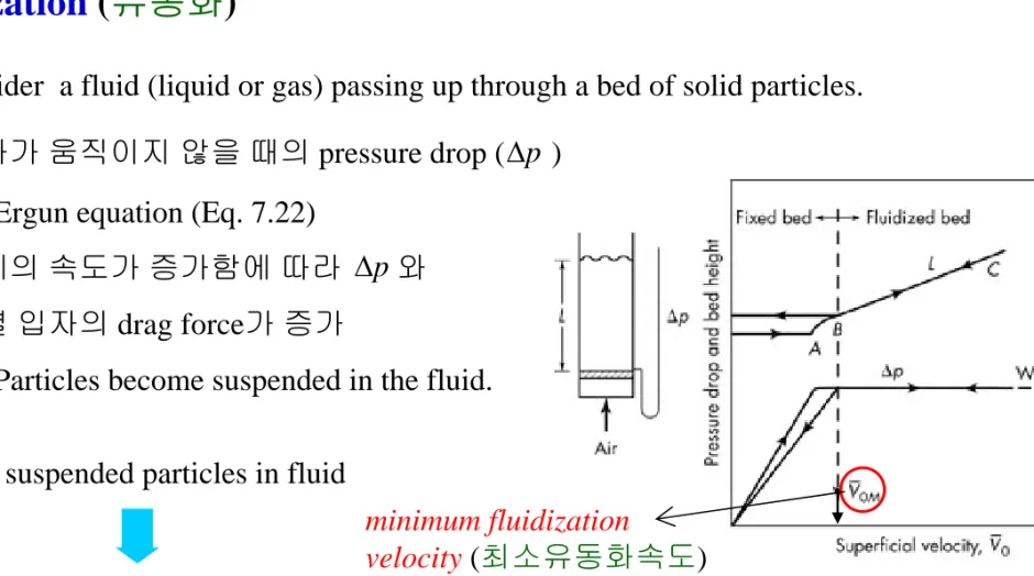
A vertical tube partly filled with a fine granular material.
open at the top, porous at the bottom, air flow from below (Fig. 7.11)
Consider a fluid (liquid or gas) passing up through a bed of solid particles.
. 입자가 움직이지 않을 때의 pressure drop ( ) Æ Ergun equation (Eq. 7.22)
. 유체의 속도가 증가함에 따라 와
개별 입자의 drag force가 증가
Æ Particles become suspended in the fluid.
Fully suspended particles in fluid
Fig. 7.11. Pressure drop & bed height vs. superficial velocity
∆p
∆p
Fluidized Bed (유동층)
minimum fluidization
velocity (최소유동화속도)
* Minimum fluidization velocity(최소유동화속도),
. Net upward force:
. Net downward force:
net gravitational & buoyant force volume of solid particles At incipient fluidization (초기유동화):
Ergun equation minimum porosity(최소공극률) (Eq. 7.22)
즉, 초기유동화가 일어나는 지점에서는 다음의 식으로 구성:
A
∆p
g L
A (1−ε)(ρp −ρ)
) )(
1
( −ε ρ − ρ
∆ =
∴ g M p
L p
V
0MÅ Two forces are equal
) 1 (
75 . 1 ) 1
( 150
3 2 0 3
2 2
0 ρ ρ
ε ρ
ε ε
µ = −
+ Φ
−
Φ s p M p
M M
M p
s
M g
D V D
V
Æ 최소유동화속도 V0M 를 구하면,
2 3 2
0 150 1
) (
p s M p M
M g D
V Φ
−
≈ −
ε ε µ
ρ ρ
2 / 3 1
0 1.75
) (
⎥⎥
⎦
⎤
⎢⎢
⎣
⎡Φ −
≈ ρ
ε ρ
ρp M
p s M
g V D
With Rep < 1,
With Rep > 103,
Å : 0.40~0.45
for roughly spherical particles εM
Related problems:
(Probs.) 7.1, 7.5, 7.6, 7.11 and 7.17