A Study on High Precision Temperature Control of an Oil Cooler for Machine Tools Using Hot-gas Bypass Method
Young-Mi Jung1⋅Jong-Yeong Byun2⋅Jung-In Yoon1⋅Seok-Kwon Jeong†
(Received September 30, 2009 ; Revised October 30, 2009 ; Accepted, November 13 2009)
Abstract:This study aims at precise control of oil outlet temperature in the oil cooler system of machine tools for enhancement of working speed and processing accuracy. PID control logic is adopted to obtain desired oil outlet temperature of the oil cooler system with hot-gas bypass method. We showed that the gains of PID controller could be easily determined by using gain tuning methods to get the gain of PID controller without any mathematical model. We also investigated various gain tuning methods to design the gains of PID and compared each control performance for selecting the optimal tuning method on the hot gas bypass method through experiments. Moreover, we confirmed excellent control performance with proposed PI controller gain even though disturbances were abruptly added to the experimental system.
Key words:Oil Cooler, Hot-gas Bypass Method, PI Control, Electronic Expansion Valve, Gain Tuning
†Corresponding Author(Pukyong National University, Division of Mechanical Engineering, E-mail: [email protected], Tel : 051-629-6181)
1 Pukyong National University, Division of Mechanical Engineering
2 Pukyong National University, Graduate School of Refrigeration & Air-conditioning Engineering
1. Introduction
Recently, working speed and processing accuracy are considered as very important factors for high productivity in the machine tools. Usually the high speed causes thermal displacement and structural deformation of the objects of machine tools.
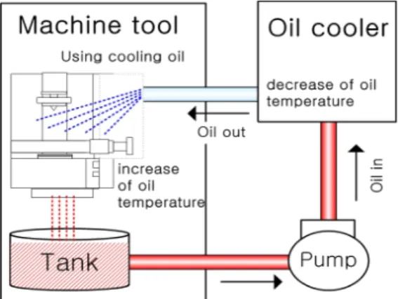
An oil cooler is an inevitable device in the machine tools to prevent the thermal deformation. The oil cooler system makes a role to reduce the thermal load of the machining parts by controlling temperature of oil used on the machine tools.
Until now on-off control method[1] has been generally adopted in the oil cooler system. But it is difficult to control temperature precisely. Also, electrical
power consumption is increased because of frequent switching operation in a compressor of the oil cooler system.
Variable speed control of a compressor[2]
and hot-gas bypass method[3~6] were developed to solve these problems. The variable speed control of a compressor with an inverter enables precise temperature control and can reduce electrical power consumption.
However, this control method needs extra device like an inverter. Therefore, it costs highly and makes structure of the oil cooler system complicated. On the other hand, the hot-gas bypass method is simple in structure and possible to control temperature comparatively precisely. For that reason, we focused on the hot-gas bypass method in this paper.
Figure 1: Schematic diagram of an oil cooler systems
Conventional researches about hot-gas bypass method were mainly focused on the evaluation of performances of a controller.
However, they did not deal with abrupt disturbances added on machine tools.
Moreover, design methodology of the controller was not investigated in detail.
In this paper, we will show the design process by the PID controller in order to obtain desired oil outlet temperature of the oil cooler. Opening angle of electronic expansion valve(EEV), hot-gas bypass valve, is considered as a control variable in this scheme.
It is important to determine gains of the PID controller appropriately satisfying control objective. In general, the gains are obtained on the basis of mathematical model. However, it is very difficult to get a practical dynamics of the controlled system. Accordingly, gain tuning method is used in this paper.
The validity of designed controller based on the gain tuning method is verified through the experiment. Moreover, we confirmed excellent control performance with proposed PI controller when disturbances were abruptly added to the
experimental system.
2. Control of an oil cooler with hot-gas bypass method
2.1 Oil cooler system with hot-gas bypass
The oil cooler system is used to control the oil temperature of machine tools as a kind of refrigerators. Low temperature oil cooled by the oil cooler system is supplied to the machining parts to reduce the thermal load.
Figure 1 shows a schematic diagram of an oil cooler type. The oil with high temperature caused by absorbing thermal load gets back to a tank and then moves to an oil cooler through a pump.
Consequently, oil outlet temperature of an oil cooler is retained as constant value to prevent thermal deformation.
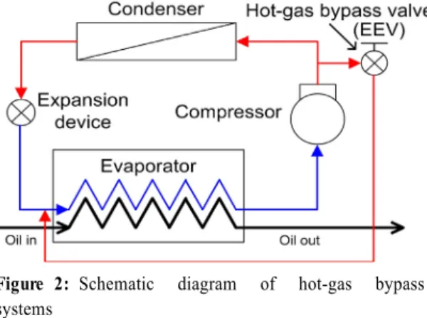
There are three types in hot-gas bypass methods. The first type is that the refrigerant which comes from the compressor's exit is sent to the evaporator's entrance. The second type is that the refrigerant which comes from the compressor's exit is sent to the evaporator's exit. The third type is that the refrigerant which comes from the compressor's exit and the condenser's exit is mixed together and then is sent to the evaporator's exit.
In the first method, the refrigerant in the compressor's exit is in a low temperature state. Therefore, it can operate an oil cooler safely. Also, it is very easy to change cooling capacity. So, we aimed at the design of control system by this method[3].
Figure 2: Schematic diagram of hot-gas bypass systems
Table 1: Specifications of EEV
Operating range 0~500 [pulse]
Rated voltage DC 12 [V]
Max working pressure 3.3 [Mpa]
(a) Appearance (b) Characteristic Figure 3: Appearance and characteristic of EEV
Figure 4: Block diagram for EEV control
Figure 2 shows schematic diagram of hot-gas bypass. The refrigerant which comes from the compressor's exit is in high-temperature and high-pressure. It is detoured to the evaporator's entrance, and it is mixed with the low-temperature and low-pressure refrigerant. It has brought that the evaporator's temperature
is increased and the cooling capacity is decreased. Therefore oil outlet temperature of an oil cooler can be retained constantly by controlling opening angle of EEV appropriately.
Table 1 indicates the main specification of the EEV. Figure 3 (a), (b) appears the appearance of EEV and variation of EEV opening angle by the pulse input respectively.
2.2 Design of a PID controller
Figure 4 is a block diagram of a PID control system for controlling the oil outlet temperature of an oil cooler.
The temperature error is sought by using an equation of , and the PID controller generates control input so that it becomes 0.
Manipulated variable is decided by the PID controller proportional - integral - derivative shown in the equation (1).
(1)Designing a PID controller is decided by the PID controller shown in the equation (1). PID controller is to decide the gains
in order to establish control purpose.
The oil cooler is composed of a compressor, an expansion device and heat exchangers.
Moreover, the components are deeply connected with pipes and valves each other. Hence, they show inherent nonlinear characteristics in operational ranges. Accordingly, it is almost impossible to identify exact dynamic characteristics and to get a practical
mathematical model of the oil cooler system. In this paper, we investigate gain tuning methods to obtain the gains of PID controller and compare each control performance for selecting the optimal tuning method on the hot gas bypass method through experiments.
Table 2: Specification of the test unit Compressor Rotary type, 1HP
Condenser Air-cooled fin and tube type Evaporator Plate heat type exchanger Refrigerant R-22
Table 3: Experimental conditions Oil flow rate 25 [l/min]
Air temperature 35 [℃]
Sampling time 1 [sec]
Figure 5: Control system of an oil cooler for a machine tool
3. Experiments
The oil cooler system usually is consisted of four components ; a compressor, a condenser, an evaporator and an expansion valve.
Figure 5 shows control system of an oil
cooler for the machine tool and configuration of experimental equipments is shown in Figure 6 . It is noted here that the bold line represents hot-gas bypass path in Figure 5.
The control parts of the oil cooler system is composed of a PLC (Programmable Logic Controller) and a stepping motor driver. Also, the PT-100, a temperature sensor, and a temperature/voltage converter are used for temperature detection and signal conversion.
The oil outlet temperature measured by the PT-100 is converted to voltage by a converter and it is transmitted to the PLC. The detected oil outlet temperature and the set value of temperature are compared with each other in the PLC, and then control error is calculated. The manipulated variable is decided so that the error becomes 0 in the PID controller.
It is sent to a stepping motor driver. The stepping motor driver controls opening angle of EEV.
In order to monitor the operating situation of the oil cooler, temperatures of main parts are measured by using a T-type thermocouple. The various information such as temperature, electric power, valve's opening angle, oil flow rate, etc. collected to a data acquisition device, and also transmitted to a PC to record the data.
The oil cooler is designed to have cooling capacity of 3.51kW under the room temperature of 35℃ and to keep the oil outlet temperature of 35℃. The thermal load of the experimental system is added by an electrical heater instead of a machine tool. Table 2 represents specification of the test unit and table 3 indicates experimental conditions.
Figure 6: Experimental equipments
4. Results and Discussions
The set point of oil outlet temperature is fixed at 35℃ considering characteristics of machine tools. The value is supposed as constant value during operation in this paper. The design objective is to maintain the oil outlet temperature within an allowable error even if disturbances are added to the system. The steady-state characteristics are considered more important than the transient characteristics in this system.
4.1 Gain tuning method of PID controller
At first, we have to determine the gains of PID controller through experimental method because it is difficult to get a practical mathematical model. The method of step response, critical oscillation and relay auto tuning are well known as t aical gain tuning method.
Figure 7, Figure 8, Figure 9 indicate experimental results of a step response, critical oscillation response and relay auto tuning response respectively. From the
Figure 7, we know that step response method are not available for tuning of PID controller. The gains of PID controller obtained from Figure 8, Figure 9 appear in Table 4.
Figure 7: Step response
Figure 8: Critical oscillation response
Figure 9: Relay auto-tuning response
Table 4: PID gain according to tuning method Tuning method Controller Kp Ki Kd
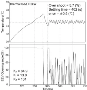
Critical oscillation PI 29.3 1.67 0 Critical oscillation PID 39.0 3.71 102 Relay auto-tuning PID 84.9 13.8 131
Figure 10: PI control response by critical oscillation
Figure 11: PID control response by critical oscillation
Figure 10, Figure 11 show control performance of PI and PID by the critical oscillation response when we set the thermal load as 2kW respectively. We know that the overshoot and error of PI control is smaller than the one of PID control.
Figure 12: PID control response by relay auto-tuning
Figure 12 appears PID control performance by relay auto tuning response. From these results, PI control gains by critical oscillation method show much better performance than examined other methods. Therefore we adopt the critical oscillation method for gain tuning.
4.2 Evaluation of control performance according to variation of load
The control performances obtained from different thermal load conditions were compared with each other.
Figure 13 (a), (b) show PI control results when we set a thermal load as 2kW and 3kW respectively. As a result, the gains of PI controller at the thermal load 3kW are (caseⅠ).
The gains of PI controller at the thermal load 2kW are (caseⅡ).
As shown in results, the overshoot of case
Ⅱ is larger approximately 1.5% than that of caseⅠ. The settling time of caseⅡ is faster about 80sec than that of caseⅠ.
Also, the steady-state errors of caseⅡ was the largest as ± 0.3℃, compared with ± 0.1℃
for caseⅠ.
Figure 14 (a), (b) show control responses when disturbances were abruptly added to the experimental system. We compare control performance with PI controller of caseⅠand that of caseⅡ when the thermal load changed from 1kW to 3kW respectively.
The steady-state error of caseⅠ was maintained within ± 0.2℃ as allowable design specification. Also it is controlled well without vibration phenomenon of the EEV to change opening angles in caseⅠ.
From the results, we know that caseⅠis better than caseⅡ.
(a) Thermal load 2kW
(b) Thermal load 3kW
Figure 13: Results of control performance with PI controller
(a) caseⅠ
(b) caseⅡ
Figure 14: PI control response by critical oscillation under abruptly added disturbance
5. Conclusions
PI controller of the oil cooler with hot-gas bypass method was designed in order to maintain oil outlet temperature as a constant set value.
The gains of PI controller were easily decided by the critical oscillation gain tuning method. Through experimental results, oil outlet temperature could be
controlled well within allowable design specification of ± 0.2℃ error range.
Moreover, the PID controller designed by the critical oscillation method showed excellent control performance even though disturbances were added to the experimental system instantaneously.
Acknowledgement
This research was financially supported by the Ministry of Education, Science Technology (MEST) and Korea Institute for Advancement of Technology(KIAT) through the Human Resource Training Project for Regional Innovation.
References
[1] Daewoo Machine Tool Institute, “ Development of high-stiffness feed mechanism and high speed spindle”, Research Report, 2003. (in Korean) [2] Youn Cheol Park, Young Chul Kim and
Man Ki Min, “Performance analysis on multi-type inverter air conditioner”, Energy Conversion and Management, pp. 1697-1682, 2001.
[3] S. W. Lee and H. K. Yeom, “Performance of thermal error controller to minimize thermal deformation of machine tools”, Proceedings of Korean Society for Precision Engineering (Spring), pp.
376-380, 2008. (in Korean)
[4] M. Yaqub, S. M. Zubair and Jameel -ur-Rehman Khan, “Performance evaluation of hot-gas bypass capacity control scheme for refrigeration and air- conditioning systems”, Energy, vol. 25, pp. 543-561, 2000.
[5] M. Yaqub, S. M. Zubair and S. H.
Khan, "Second-law-based thermodynamic analysis of hot-gas by pass, capacity-control schemes for refrigeration and air-conditioning systems".
Energy-The International Journal, vol.
20, no. 6, pp. 483-493, 1998.
[6] S. W. Lee and C .W. Lee, “Assessment capability of oil cooler with hot-gas”, Proceedings of Korean Society for Precision Engineering, No. 6, pp.
459-460, 2007. (in Korean)
Author Profile
Young-Mi Jung
1She graduated in doctoral course of Department of Mechanical &System Eng. from Yokohama National University in Japan in 2009. She is currently a part time instructor in Dept. of Mechanical Engineering at Pukyong National University.
Jong-Yeong Byun
He graduated in the Dept. of Refrigeration&Air-conditioning Engineering from Pukyong National Univ. in 2006. He is currently a graduate student in Dept.
of Refrigeration&Air-conditioning Engineering at Pukyong National University.
Jung-In Yoon
He graduated with Dr. engineering from Tokyo University of A&T. He is a professor of Mechanical engineering department of the Pukyong National University. Editing director of the Korean Society of Marine Engineering. Editing director of the Korean Society of Power System Engineering.
Editing director of the Korean Society of Air-Conditioning and Refrigerating Engineers.
Seok-Kwon Jeong
He graduated in master and doctoral course of Department of Electrical
&Computer Eng. from Yokohama National University in Japan on 1992 and 1995.
He is a professor in Dept. of Mechanical Engineering at Pukyong National University. His main research area is automatic control design for refrigeration & air-conditioning system, fault diagnosis, fault tolerant control, reliability of a compressor for a refrigerator, etc.
![Table 3: Experimental conditions Oil flow rate 25 [l/min]](https://thumb-ap.123doks.com/thumbv2/123dokinfo/4842146.283295/4.786.84.380.450.836/table-experimental-conditions-oil-flow-rate-l-min.webp)