한국정보통신학회논문지 Vol. 25, No. 8: 1130-1133, Aug. 2021
1130
호흡 검출 시스템을 위한 초소형 센서 인터페이스 회로
Miniaturized Sensor Interface Circuit for Respiration Detection System
Sung-Hun Jo
**Assistant professor, Department of Electronic Engineering, Dongseo University, Busan, 47011 Korea
ABSTRACT
In this paper, a miniaturized sensor interface circuit for the respiration detection system is proposed. Respiratory diagnosis is one of the main ways to predict various diseases. The proposed system consists of respiration detection sensor, temperature sensor, and interface circuits.
Electrochemical type gas sensor using solid electrolytes is adopted for respiration detection. Proposed system performs sensing, amplification, analog-to-digital conversion, digital signal processing, and i2c communication. And also proposed system has a small form factor and low-cost characteristics through optimization and miniaturization of the circuit structure. Moreover, technique for sensor degradation compensation is introduced to obtain high accuracy. The size of proposed system is about 1.36 cm
2.
Keywords : Sensor interface circuit, Respiration detection system, Compensation technique, Low-cost miniaturized electronics
Ⅰ. Introduction
In recent years, the focus of healthcare has shifted to disease prevention rather than disease treatment, which led to increased attention on biomedical device for the disease prediction [1]. Respiratory diagnosis is one of the main ways to predict various diseases such as asthma,
lung cancer, diabetes, kidney disease, and so on [2].
Most respiratory diagnostic systems have been developed as small hand-held devices [3]. Thus, considering the convenience of use, small form factor of device is necessary. In addition, it is encouraged to use as a disposable device to prevent droplet infections caused by multiple use of several people [4]. To do this, cost reduction by optimizing and minimizing the system configuration is required. Moreover, because environmental factors such as temperature and gas concentration can cause sensor accuracy degradation, compensation technique is essential [5]. In this paper, low-cost miniaturized respiration detection system having accuracy compensation technique is proposed.
Ⅱ. Proposed System Architecture
The proposed system consists of respiration detection sensor, temperature sensor, and interface circuits as shown in Fig. 1. Temperature sensor is used to compensate the output of respiration detection sensor.
Interface circuits include amplifier, micro controller unit (MCU), low-dropout (LDO) regulator, and passive components. MCU has an inbuilt multi-channel 10-bit analog-to-digital converter (ADC) [6]. The output of respiration detection sensor processed by interface circuits is transmitted to an external monitoring device through I2C communication. The LDO regulator which receives external power through a DC adapter supplies a voltage of 2.1 V to the sensors and interface circuits.
Electrochemical type gas sensor using solid electrolytes is adopted for respiration detection. Sensor generates an electromotive force (EMF) which is proportional to the logarithm of the concentration of carbon dioxide.
Received 29 June 2021, Revised 15 July 2021, Accepted 30 July 2021
* Corresponding Author Sung-Hun Jo(E-mail:[email protected], Tel:+82-51-320-4226) Assistant professor, Department of Electronic Engineering, Dongseo University, Busan, 47011 Korea
Open Access
http://doi.org/10.6109/jkiice.2021.25.8.1130
print ISSN: 2234-4772 online ISSN: 2288-4165Short Paper
한국정보통신학회논문지 Vol. 25, No. 8: 1130~1133, Aug. 2021
호흡 검출 시스템을 위한 초소형 센서 인터페이스 회로
1131
Fig. 1 Overall architecture of proposed systemSensor has four terminals: one power terminal, two ground terminals, and one EMF terminal. EMF of sensor is applied to the interface circuit. Since the interface circuit having high input impedance is required to process the EMF of sensor, the proposed system consists of a non-inverting amplifier configuration which has measured input resistance of about 2 TΩ and the input capacitance of about 15 pF. Also, it has a voltage gain of 2.1 V/V. The input voltage applied in amplifier is changed according to the EMF change of sensor. The output voltage of amplifier is connected to ADC.
Thermistor is mounted as a temperature sensor, which is connected in series with a reference resistor of 10 kΩ [7].
In other words, it forms a voltage divider structure between VDD and GND. Thermistor is temperature- dependent resistor whose resistance varies with the change of temperature. Hence, the output of voltage divider circuit is varied according to the change of temperature, which is directly applied to the ADC.
The ADC embedded in the MCU uses successive- approximation register (SAR) principle [6]. Since the power consumption is proportional to the clock frequency, the ADC clock frequency is lowered as much as possible within the recommended range to reduce the power consumption of the interface circuit.
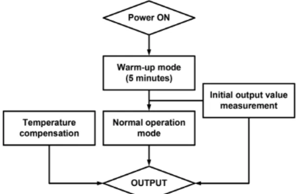
Fig. 2 Operation diagram of proposed system
SAR ADC has clock frequency of 62.5 kHz which is obtained through dividing the 1 MHz reference clock frequency by 16.
To implement the proposed system, various commercial
components are employed including LDO regulator
(NCP706MX21TAG, ON Semiconductor), Amplifier
(TLV521DCKT, Texas Instruments), Thermistor
(NCP15XH103F03RC, Murata), and MCU (ATtiny45,
Microchip). The operation diagram of the proposed
sensor system is shown in Fig. 2. When power is applied
to the proposed system, it is implemented to be in a
standby state without signal processing for the initial 5
minutes considering the time to reach the steady state of
the sensor. After initial 5 minutes, ADC reads the sensor
output as much as a thousand at about 200 microseconds
intervals, then calculates the average and stores it as the
initial output value of the sensor. Stored initial output
value of the sensor becomes the reference value for a
carbon dioxide concentration of 400 ppm. After that,
during normal operation, the ADC reads a hundred
sensor output at about 200 microseconds intervals each
time, and then stores the average value as an output
value of sensor. Likewise, the ADC reads a hundred
thermistor output at about 200 microseconds intervals
each time, and then stores the average value as an output
value of thermistor.
한국정보통신학회논문지 Vol. 25, No. 8: 1130-1133, Aug. 2021
1132
Ⅲ. Experimental results and discussions
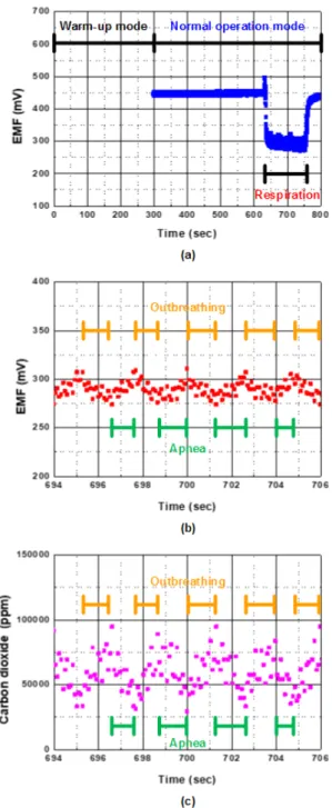
Fig. 3 Measurement results (a) warm-up mode and normal- mode (b) electromotive force(EMF) (c) carbon dioxide concentration
For respiration detection, carbon dioxide concentration is calculated based on Equation (1) [8]. E0 is the initial output value of the sensor after warm-up mode. E is the output value of the sensor in normal operation mode. E0 and E have a unit of volt (V). T exhibits the output value of thermistor having Celsius (°C) temperature unit.
( )
( )
0
10079.83 7231 25
400 10
2 E ET C
Carbon dioxide
ppm- ´
+ - °
= ´ (1)
Proposed thermistor has nominal resistance of 10 kΩ at 25°C. The B coefficient of thermistor represents a degree of sensitivity to temperature changes, which has a different value depending on the target temperature range. When the target temperature range is 25°C to 50
°C, the B coefficient value is 3380 [7]. In order to convert the thermistor's resistance to temperature, the following Steinhart-Hart equation is used [9].
0 0
1 1 1
ln R
T T B R
æ ö
= + ç ÷
è ø (2)
T represents temperature in Kelvin (K) unit. T
0is nominal temperature at about 298.15 K which is equal to 25°C. B is coefficient of the thermistor. R and R
0are measured resistance and nominal resistance of thermistor, respectively.
The measurement results of the sensor system according to the respiration are shown in Fig. 3. It is in warm-up mode until 300 seconds after power is initially applied. After the warm-up mode is over, the initial output value is measured. The measured initial output value in Fig. 3(a) is about 446 mV. After that, it enters the normal operation mode. Respiration was occurred between about 630 seconds and 760 seconds. Fig. 3(b) shows the enlarged graph between 694 and 706 seconds.
EMF of sensor is changed according to the respiration,
which varies by up to about 40 mV depending on the
outbreathing and apnea. In the apnea stage, sensor shows
recovery characteristic into steady state. Fig. 3(c) shows
the concentration of carbon dioxide according to
outbreathing and apnea in a range between 694 and 706
호흡 검출 시스템을 위한 초소형 센서 인터페이스 회로
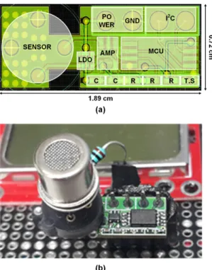
1133 seconds. It can be seen that a change in concentration of carbon dioxide of up to about 65000 ppm is detected depending on the outbreathing and apnea. Appearance of proposed system is shown in Fig. 4. It consists of sensor and electronics, which has an area of 1.36 cm
2.
Ⅳ. Conclusion
Respiration detection system having optimized and miniaturized sensor interface circuit is implemented.
Compensation through measurement of initial output value and temperature is performed to prevent sensor accuracy degradation due to environmental change and sensor deterioration. The proposed system can be used to detect the concentration of carbon dioxide produced by respiration, which only occupies an area of 1.36 cm
2.
ACKNOWLEDGEMENT
This work was supported by the Dongseo University Research Fund of 2020. (DSU-20200028)
References
[ 1 ] Y. Fu and J. Guo, “Blood Cholesterol Monitoring With Smartphone as Miniaturized Electrochemical Analyzer for Cardiovascular Disease Prevention,” IEEE Transactions on Biomedical Circuits and Systems, vol. 12, no. 4, pp. 784- 790, Aug. 2018.
[ 2 ] S. Bagchi, S. SenGupta, and S. Mondal, “Development and Characterization of Carbonic Anhydrase-Based CO2 Biosensor for Primary Diagnosis of Respiratory Health,”
IEEE Sensors Journal, vol. 17, no. 5, pp. 1384-1390, Mar.
2017.
[ 3 ] L. Scholz, A. Ortiz Perez, B. Bierer, P. Eaksen, J.
Wollenstein, and S. Palzer, “Miniature Low-Cost Carbon Dioxide Sensor for Mobile Devices,” IEEE Sensors Journal, vol. 17, no. 9, pp. 2889-2895, May. 2017.
[ 4 ] M. Bhattacharjee, P. Escobedo, and R. Dahiya, “Disposable and Flexible Sensor Patch for α-amylase Detection in Human Blood Serum,” in Proceeding of IEEE SENSORS, pp. 1-4, 2020.
[ 5 ] J. Leis and D. Buttsworth, “A Temperature Compensation Technique for Near-Infrared Methane Gas Threshold Detection,” IEEE Transactions on Industrial Electronics, vol. 63, no. 3, pp. 1813-1821, Mar. 2016.
[ 6 ] ATTINY45 datasheet [Internet]. Available:
https://www.microchip.com/wwwproducts/en/ATTINY45.
[ 7 ] NCP15XH103F03RC datasheet [Internet]. Available:
https://www.murata.com/en-global/products/productdetail?
partno=NCP15XH103F03RC.
[ 8 ] T. Kim, J. Kim, S. Lee, and C. Park, “Humidity effects on the initial stabilization behavior of a solid electrochemical CO2 sensor,” Sensors and Actuators B: Chemical, vol. 295, pp. 65-69, 2019.
[ 9 ] J. Lorenzo, A. Lazaro, R. Villarino, and D. Girbau,
“Modulated Frequency Selective Surfaces for Wearable RFID and Sensor Applications,” IEEE Transactions on Antennas and Propagation, vol. 64, no. 10, pp. 4447-4456, Oct. 2016.
Fig. 4 Appearance of proposed system (a) layout (b) top-view