모드 변형에너지기반 손상 모니터링
Modal Strain Energy-based Damage Monitoring in Beam Structures using PZT's Direct Piezoelectric Response
호 득 유이* 이 포 영** 김 정 태†
Ho, Duc-Duy Lee, Po-Young Kim, Jeong-Tae
···
요 지
본 연구에서는 PZT 소자의 정압전 효과에 의한 동적 응답신호를 이용하는 보 구조물 손상 모니터링 기법을 제안하였다.
특히, 모드 변형에너지기반 보 구조물 손상 모니터링에 PZT 정압전 응답신호를 입력자료로 활용하는 방안에 대한 연구에 주안점이 있다. 먼저, PZT 소자의 정압전 효과 및 동적 변형률 응답의 이론적 배경을 요약하였다. 다음으로, 모드 변형에너 지기반 보 구조물 손상위치 모니터링 기법을 제시하였다. 제시된 기법의 적합성을 검증하기 위해, 캔틸레버 보 모형을 대 상으로 강제진동 실험을 수행하였으며, 세 종류의 센서(가속도계, PZT 센서, 변형률계)를 통해 동적 응답신호가 계측되었 다. 손상 전후에 계측된 이들 진동신호들을 사용하여 모드 변형에너지기반의 손상위치 모니터링이 수행되었다.
핵심용어 : 모드 변형에너지, 손상검색, 캔틸레버보, PZT, 정압전응답
Abstract
The main objective of this study is to examine the feasibility of using lead zirconate titanate (PZT)'s direct piezoelectric response as vibrational feature for damage monitoring in beam structures. For the purpose, modal strain energy (MSE)-based damage monitoring in beam structures using dynamic strain response based on the direct piezoelectric effect of PZT sensor is proposed in this paper. The following approaches are used to achieve the objective. First, the theoretical background of PZT's direct piezoelectric effect for dynamic strain response is presented. Next, the damage monitoring method that utilizes the change in MSE to locate of damage in beam structures is outlined. For validation, forced vibration tests are carried out on lab-scale cantilever beam. For several damage scenarios, dynamic responses are measured by three different sensor types (accelerometer, PZT sensor and electrical strain gage) and damage monitoring tasks are performed thereafter. The performance of PZT's direct piezoelectric response for MSE-based damage monitoring is evaluated by comparing the damage localization results from the three sensor types.
Keywords : modal strain energy, damage detection, cantilever beam, PZT, direct piezoelectric response
···
†책임저자, 정회원・부경대학교 해양공학과 교수 Tel: 051-629-6585 ; Fax: 051-629-6590 E-mail: [email protected]
* 학생회원・부경대학교 해양공학과 박사과정
** 학생회원・부경대학교 해양공학과 석사과정
∙이 논문에 대한 토론을 2012년 4월 30일까지 본 학회에 보내주시 면 2012년 6월호에 그 결과를 게재하겠습니다.
1. Introduction
A significant amount of research has been conducted in the area of damage monitoring in structures.
Many research studies for monitoring damage location and severity in a structure via changes in vibration responses have been performed by many researchers.
For example for beams, attempts have been made to relate changes in natural frequencies to such influences as cracks and local geometrical changes (Gudmunson, 1982; Cristides and Barrs, 1990) and to identify the damage location and magnitude from the measured vibrational modes (Kim and Stubbs, 1995).
Vibration-based structural health monitoring (SHM)
has become increasingly important for many fields such as aerospace engineering and civil engineering in recent years. For example, changes in natural frequencies and mode-shape features extracted from acceleration signals have been used to identify damage location and damage severity (Kim et al., 2003). At the same time, there has been many efforts on developing new sensors and devices for monitoring the integrity of structures. So many kind of smart sensors and damage detection techniques have been employed (Liang et al., 1996; Sirohi and Chopra, 2000; Farrar, 2001; Kim et al., 2003).
Consequently, there exists an issue that how to select the cost-effective and reliable system for SHM purpose. Up-to-dated sensing techniques for vibration- based SHM have the following problems. First, the cost associated with acceleration measurement system is very high due to the high-cost of accelerometers.
Second, the wired measurement system is very bulky and inconvenient for field test.
In order to reduce the cost of acceleration-based SHM system, recently, a method of measuring dynamic strain using piezoelectric sensors has been developed (Sirohi and Chopra, 2000). This method is promising since the lead zirconate titanate (PZT)'s direct piezoelectric effect can be easily transformed into dynamic strain response and the cost of PZT sensor is very cheap. Moreover, wireless sensor technology developed by many researchers (e.g., Lynch et al., 2006; Mascarenas et al., 2007; Rice et al., 2010;
Kim et al., 2011) can be incorporated with the PZT sensor as the feasible smart sensor system. By using this smart sensor system, therefore, the costs are greatly reduced and the data management and processing is more effective via on-board computation.
The main objective of this study is to examine the feasibility of using PZT's direct piezoelectric response as vibrational feature for damage monitoring in beam structures. For the purpose, modal strain energy (MSE)-based damage monitoring in beam structure using dynamic strain response based on the direct piezoelectric effect of PZT sensor is proposed in this paper. The following approaches are used to achieve
the objective. First, the theoretical background of PZT's direct piezoelectric effect for dynamic strain response is presented. Next, the damage monitoring method that utilizes the change in MSE to locate of damage in beam structures is outlined. For validation, forced vibration tests are carried out on lab-scale cantilever beam. For several damage scenarios, dynamic responses are measured by three different sensor types (accelerometer, PZT sensor and electrical strain gage) and damage monitoring tasks are performed thereafter. The performance of PZT's direct piezoelectric response for MSE-based damage monitoring is evaluated by comparing the damage localization results from the three sensor types.
2. Theoretical Backgrounds
2.1 Dynamic Strain Response from PZT's Direct Piezoelectric Effect
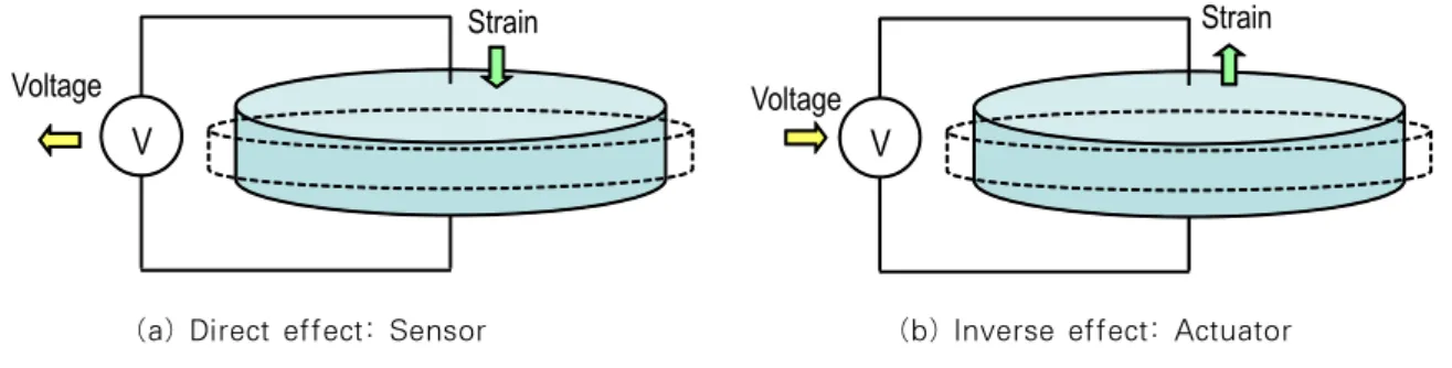
Piezoelectric materials are commonly used as both sensors (direct effect) and actuators (inverse effect) for SHM applications (Liang et al., 1996; Sirohi and Chopra, 2000). A key characteristic of these materials is the utilization of the direct effect to sense structural deformation in addition to the inverse piezoelectric effect to actuate the structure. The constitutive equations in strain-charge relation for a piezoelectric material can be expressed by tensor form as (Sirohi and Chopra, 2000):
(1)
(2)
where is the electrical displacement;
is the dielectric permittivity at zero mechanical stress (
=0); is the electric field vector; and are the piezoelectric coefficients; is the stress vector;
is the strain vector; is the elastic compliance of the piezoelectric material at zero electric field (
=0).
Equation (2) shows that when an electric field
V
Strain Voltage
V
Strain Voltage
(a) Direct effect: Sensor (b) Inverse effect: Actuator Fig. 1 Piezoelectric sensor: Direct and inverse effects
1
3 2
Host Structure
ε1 ε1
PZT Patch ~ E3
Fig. 2 1-D PZT-structure interaction in direct piezoelectric effect
(directly related to electrical voltage) is applied to two surfaces of a PZT sensor, a strain field is induced.
As the inverse effect given in Eq. (1), the electrical displacement (directly related to electrical current) is induced since a mechanical stress field (or mechanical strain field) is applied to a PZT sensor. These effects are conceptually explained in Fig. 1. According to the direct effect and the inverse effect, a PZT sensor can be used as both a sensor and an actuator.
As shown in Fig. 2, the PZT material can be employed as a sensor for dynamic strain measurement.
Strain is measured in terms of the charge generated by PZT sensor as a result of direct effect. When a PZT sensor is mechanically strained, an electrical field is produced. The constitutive relations of the PZT strain for 1-D interaction:
(3)
(4)
where is the electric displacement; is the dielectric constant of piezoelectric wafer; is the applied external electric field in direction 3; is
the piezoelectric coupling constant; is the stress in direction 1; is the strain in direction 1; is the complex Young’s modulus of the zero-electric field.
If the PZT sensor bonded on surface of host structure is desired to be used as sensor only, without external electric field across its terminals, the strain in the PZT sensor can be expressed in terms of the voltage measured across its terminals as (Sirohi and Chopra, 2000):
(5)where is the output voltage across the terminals of the PZT sensor; is the thickness of PZT sensor.
From Eq. (5), the dynamic strain is determined from the output voltage which is easily measured directly.
By using Eq. (5), the dynamic strain is calculated from the dynamic output voltage. However, in order to improve measurement accuracy, the output voltage of PZT sensor should be passed through some signal conditioning circuits (Sirohi and Chopra, 2000). It should be noted that the derivation of Eq. (5) was based on the assumption that only strain in 1-D contributed to the charge generated, the effect of other strain components was negligible, and that there is no loss of strain in the bond layer. In reality, however, a transverse component of strain exists and there are some losses in finite thickness bond layer (Bhalla et al., 2009). As a result, the value of strain as calculated by Eq. (5) is not the actual strain
measured by the strain gage. For this reason, some correction factors should be required to account for transverse strain and shear lag losses in the bond layer. Moreover, the effect of temperature on sensor characteristics should be considered for accuracy measurement of dynamic strain using PZT sensor. The properties of PZT sensor are very sensitive to tem- perature (Kim et al., 2011). Therefore, the dynamic strain should be measured at known temperature conditions, then, it should be modified by using appropriate values of the constants for calibration.
2.2 MSE-based Damage Monitoring Method
Modal strain energy (MSE) is one of damage sensitive features using mode shape curvature. Kim et al. (2003) proposed an MSE-based damage monitoring method by measuring the fractional change in MSE.
For a beam structure, damage in the member is defined as the relative change between undamaged flexural stiffness, , and damaged one,
, of the same element. For available vibration modes, the MSE-based damage index is for location, , is given by
(6)
where and are the modal stiffness and the contribution of the element to the modal stiffness, respectively. The asterisk (*) denotes the damaged state. ,
and are formulated as follows (Kim et al., 2003):
″
,
″
and
″
. The term ″
is the mode shape curvature determined from the
mode shape vector . The term is a dimensionless factor representing the fractional changes in the natural frequencies ( ).
For the damage localization, the damage indices are normalized according to the standard rule as
(7)
where and are the mean and standard deviation of the collection of values, respectively.
Then, the damage is localized from the statistical hypothesis tests. The null hypothesis (i.e., ) is taken to be the structure undamaged at the
element and the alternate hypothesis (i.e., ) is taken to be the structure damages at the element.
In assigning damage to a particular location, the following decision rule is utilized: first, choose if
≥; or choose if , where is the statistical criterion depending upon the confidence level of the localization test. As a result, the damage is assigned to the location if exceeds the confidence level.
The MSE-based damage monitoring is performed in the following four steps: firstly, vibration signals (e.g., acceleration or dynamic strain) are measured at distributed locations; secondly, vibration features such as natural frequency and mode shape for entire structure are extracted by using modal identification methods such as frequency domain decomposition (FDD) method or stochastic subspace identification (SSI) method (Brincker et al., 2001; Yi and Yun, 2004); and the MSE-based damage index and also normalized damage index are computed from Eqs. (6) and (7) and post-processed modal data; and finally, the location of damage is estimated by the statistical hypothesis tests stated above.
3. Experimental Validation
3.1 Experiments on Lab-scale Beam
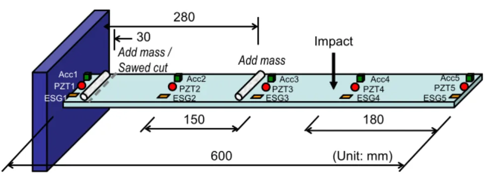
Dynamic tests were performed on a lab-scale 600×60×10-mm aluminum cantilever beam as shown in Fig. 3. Five sensor locations were arranged along the beam with a constant interval 150mm and the
600
Impact
Acc1
ESG1
150 180
PZT1 Acc2
ESG2PZT2
30
Add mass
(Unit: mm)
Acc5 ESG5 Acc3 PZT5
ESG3PZT3 Acc4
ESG4PZT4
Add mass / Sawed cut
280
Acc
PZT ESG
(a) Test beam (b) Three sensor types
Fig. 3 Experimental setup for lab-scale beam impact force was applied at a location 180mm
distanced from the free end. At one sensor location, three different sensor types (i.e., accelerometer, PZT sensor, electrical strain gage) were installed. As a result, three responses were measured from accelero- meters, PZT sensors and electrical strain gages. For acceleration measurement, Dytran 3101BG accelero- meters, with the nominal sensitivity of 100 mV/g, were used. The data acquisition system consists of 16-channel PCB signal conditional, DAQ card, terminal block and Laptop with MATLAB software.
For dynamic strain measurement from PZT sensor, FT-20T-3.6A1 PZT sensors were used. The data acquisition system consists of DAQ card, terminal block and Laptop with MATLAB software. For dynamic strain measurement from electrical strain gage, TML FLA-5-11-1L strain gages were used. The data acquisition system consists of TML SB120B bridge boxes, Kyowa EDX-100A universal recorder and Laptop with DCS-100A software.
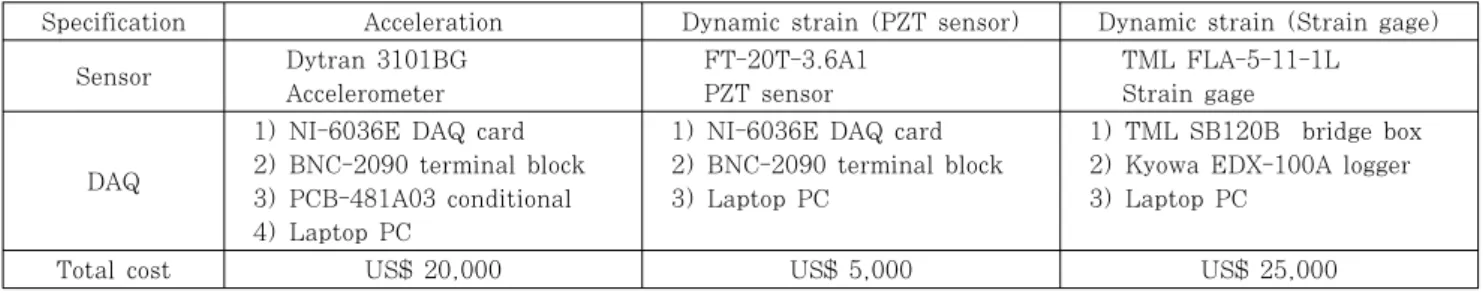
Table 1 gives the information about three measure- ment system for acceleration from accelerometer, dynamic strain from PZT sensor and dynamic strain from electrical strain gage. The cost for measuring dynamic strain from PZT sensors is lowest (i.e., about 10% cost for acceleration measurement).
However, PZT sensor has the following weak points in comparison to electrical strain gage. First, the quality of PZT sensor much depends on the time.
Second, it is not easy to make the same PZT sensors which are necessary for SHM applications.
3.2 Vibration Responses of Test Beam
Dynamic responses were measured in vertical direction with sampling frequency of 1 kHz. Frequency domain decomposition (FDD) method (Brincker et al., 2001) was employed to extract frequency responses and modal parameters. Three damage cases were inflicted on test beam as given in Table 2. A 2.4 N mass was added on the beam at 30mm (i.e., damage case 1) or 280mm (i.e., damage case 2) from the fixed end. For damage case 3, a cut was sawed along the width of beam at a location 30mm from fixed end, as shown in Fig. 3(a). The crack-size was considered with ratio of crack depth (a) and beam thickness (t) of 0.2.
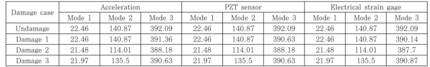
Fig. 4 shows the time history responses at sensor location 3 for three different sensor types. Fig. 5 and Fig. 6 show frequency responses and mode shape curvatures for first three bending modes, respectively. The natural frequencies measured by three sensor types are also given in Table 3. It is observed that the responses show good agreement for three sensor types. Frequency response from electrical strain gages contains high noise level in comparison with those from accelerometers and PZT sensors. It should be noted that mode shape curvatures used for MSE-based damage monitoring method described in section 3 are extracted directly in case of using PZT sensors and electrical strain gages. Meanwhile, for accelerometers, one more step is required to determine mode shape curvatures from mode shapes.
Specification Acceleration Dynamic strain (PZT sensor) Dynamic strain (Strain gage) Sensor Dytran 3101BG
Accelerometer
FT-20T-3.6A1 PZT sensor
TML FLA-5-11-1L Strain gage
DAQ
1) NI-6036E DAQ card 2) BNC-2090 terminal block 3) PCB-481A03 conditional 4) Laptop PC
1) NI-6036E DAQ card 2) BNC-2090 terminal block 3) Laptop PC
1) TML SB120B bridge box 2) Kyowa EDX-100A logger 3) Laptop PC
Total cost US$ 20,000 US$ 5,000 US$ 25,000
Table 1 Three-types of vibration measurement systems
Case Damage-type Damage-size Location (x/L) Note
Damage 1 Add mass Add-mass 2.4N 30mm (0.05) Add mass equivalent to 26% of beam weight Damage 2 Add mass Add-mass 2.4N 280mm (0.47) Add mass equvalent to 26% of beam weight Damage 3 Sawed cut a/t=0.2 30mm (0.05) a is crack depth; t is beam thickness
Table 2 Damage scenarios on test beam
0 1 2 3 4 5
-0.1 -0.05 0 0.05 0.1
Time (s)
Acceleration (g)
0 1 2 3 4 5
-3 -2 -1 0 1 2 3
Time (s)
Voltage (V)
0 1 2 3 4 5
-40 -20 0 20 40
Time (s) Strain (10-6 m/m)
(a) Accelerometer (b) PZT sensor (c) Electrical strain gage
Fig. 4 Time history responses of test beam
0 100 200 300 400 500
10-8 10-6 10-4 10-2 100
Frequency (Hz) Singular Value Decomposition AccMode 1 Mode 2
Mode 3
0 100 200 300 400 500
10-5 100 105
Frequency (Hz)
Singular Value Decomposition PZT
Mode 1 Mode 2
Mode 3
0 100 200 300 400 500
100 102 104 106
Frequency (Hz) Singular Value Decomposition ESGMode 1
Mode 2
Mode 3
(a) Accelerometer (b) PZT sensor (c) Electrical strain gage
Fig. 5 Frequency responses of test beam
1 2 3 4 5
-1 -0.8 -0.6 -0.4 -0.2 0
Sensor Location
Modal Amplitude Acc
PZT ESG
1 2 3 4 5
-0.8 -0.6 -0.4 -0.2 0 0.2 0.4 0.6
Sensor Location
Modal Amplitude Acc
PZT ESG
1 2 3 4 5
-0.8 -0.6 -0.4 -0.2 0 0.2 0.4 0.6
Sensor Location
Modal Amplitude
ode 3
Acc PZT ESG
(a) Mode 1 (b) Mode 2 (c) Mode 3
Fig. 6 Mode shape curvatures of test beam
Damage case Acceleration PZT sensor Electrical strain gage
Mode 1 Mode 2 Mode 3 Mode 1 Mode 2 Mode 3 Mode 1 Mode 2 Mode 3
Undamage 22.46 140.87 392.09 22.46 140.87 392.09 22.46 140.87 392.09
Damage 1 22.46 140.87 391.36 22.46 140.87 390.63 22.46 140.87 390.14
Damage 2 21.48 114.01 388.18 21.48 114.01 388.18 21.48 114.01 387.7
Damage 3 21.97 135.5 390.63 21.97 135.5 390.63 21.97 135.5 390.87
Table 3 Natural frequency (Hz) of test beam measured by three sensor types
0 100 200 300 400 500 600
-2 -1 0 1 2 3 4 5
Length (mm)
Normalized Damage Index
Inflicted Damage
Zo= 2.4 (99.18%)
0 100 200 300 400 500 600
-2 -1 0 1 2 3 4 5
Length (mm)
Normalized Damage Index
Inflicted Damage
Zo= 2.4 (99.18%)
0 100 200 300 400 500 600
-2 -1 0 1 2 3 4 5
Length (mm)
Normalized Damage Index
Inflicted Damage
Zo= 2.2 (98.61%)
(a) Accelerometer (b) PZT sensor (c) Electrical strain gage
Fig. 7 MSE-based damage localization results: Damage 1
0 100 200 300 400 500 600 -2
-1 0 1 2 3
Length (mm)
Normalized Damage Index
Inflicted Damage Zo= 1.8 (96.41%)
0 100 200 300 400 500 600
-2 -1 0 1 2 3
Length (mm)
Normalized Damage Index
Inflicted Damage Zo= 1.8 (96.41%)
0 100 200 300 400 500 600
-2 -1 0 1 2 3
Length (mm)
Normalized Damage Index
Inflicted Damage Zo= 1.7 (95.54%)
(a) Accelerometer (b) PZT sensor (c) Electrical strain gage
Fig. 8 MSE-based damage localization results: Damage 2
0 100 200 300 400 500 600
-2 0 2 4 6
Length (mm)
Normalized Damage Index
Inflicted Damage
Zo= 2.14 (98.41%)
0 100 200 300 400 500 600
-2 0 2 4 6
Length (mm)
Normalized Damage Index
Zo= 2.32 (98.99%)
Inflicted Damage
0 100 200 300 400 500 600
-2 0 2 4 6
Length (mm)
Normalized Damage Index
Zo= 2.3 (98.94%)
Inflicted Damage
(a) Accelerometer (b) PZT sensor (c) Electrical strain gage
Fig. 9 MSE-based damage localization results: Damage 3 3.3 MSE-based Damage Localization Results
As described in section 2.2, MSE-based damage monitoring method proposed by Kim et al. (2003) was employed to estimate the damage localization. The damage localization index, as described in Eqs. (6)
and (7), is calculated from the fractional change in MSE between undamage and damage cases. Fig. 7~9 show MSE-based damage localization results for three damage cases, respectively, by using three sensor types (i.e., accelerometer, PZT sensor and electric strain gage). It is observed that the damage locations
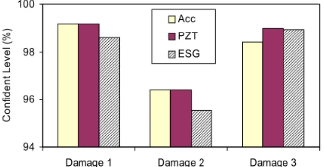
94 96 98 100
Damage 1 Damage 2 Damage 3
Confident Level (%) Acc
PZT ESG
Fig. 10 MSE-based damage detectability for three sensor types
are well localized as shown in Fig. 7~9. The confidence levels were up to 96%. As shown in Fig. 10, for damage cases 1 and 2, the confidence levels in case of using electrical strain gage are relative lower than those in case of using accelerometer and PZT sensor.
As also shown in Fig. 10, for cantilever beam, it is easier to detect the damage near fix-end location than mid-span location. As a result, the fix-end location is more critical than mid-span location for cantilever beam. Compared to the results by the accelerometer and the electrical strain gage, the damage localization results by the PZT sensor were accurate with high confidence level for all damage cases.
4. Conclusions
In this paper, the feasibility of using lead zirconate titanate (PZT)'s direct piezoelectric response as vibrational feature for damage monitoring in beam structures was examined. First, the theoretical background of PZT's direct piezoelectric effect for dynamic strain response was presented. Next, the damage monitoring method that utilizes the change in modal strain energy (MSE) to locate the severity of damage in beam structures was outlined. For validation, experiments were carried out on lab-scale aluminum cantilever beam. For several damage scenarios, dynamic responses were measured by three different sensor types (i.e., accelerometer, PZT sensor and electrical strain gage) and damage monitoring tasks were performed thereafter. The vibration responses showed good agreement for three sensor
types. The performance of PZT's direct piezoelectric response for MSE-based damage monitoring was successfully evaluated by comparing the damage localization results from the three sensor types. The damage locations were well localized with high confidence level.
Acknowledgements
This work was supported by the Innovations in Nuclear Power Technology of the Korea Institute of Energy Technology Evaluation and Planning (KETEP) grant funded by the Korea government Ministry of Knowledge Economy (2010T100101077). Also, the authors would like to thank the support of the Second Stage Brain Korea 21 (BK21) Program of Korean Government.
References
Bhalla, S., Praveen, K., Gupta A., Datta T.K.
(2009) Simplified Impedance Model for Adhesively Bonded Piezo-Impedance Transducers, Journal of Aerospace Engineering, 22(4), pp.373~382.
Brincker, R., Zhang. L., Andersen, P. (2001) Modal Identification of Output-only using Frequency Domain Decomposition, Smart Materials and Structures, 10, pp.441~445.
Cristides, S., Barrs, A.D.S. (1990) On-orbit Damage Assessment for Large Space Structures, AIAA Journal, 26, pp.1119~1126.
Farrar, C.R. (2001) Historical Overview of Structural Health Monitoring, Lecture Notes on Structural Health Monitoring Using Statistical Pattern Recognition, Los Alamos Dynamics, Los Alamos, NM.
Gudmunson, P. (1982) Eigenfrequency Changes of Structures Due to Cracks, Notches or other Geometric Changes, Journal of the Mechanics and Physics of Solids, 30, pp.339~353.
Kim, J.T., Stubbs, N. (1995) Model-Uncertainty Impact and Damage-Detection Accuracy in Plate Girder, Journal of Structural Engineering, 121(10), pp.1409~1417.
Kim, J.T., Park, J.H., Hong, D.S., Ho, D.D. (2011) Hybrid Acceleration-Impedance Sensor Nodes on
Imote2-platform for Damage Monitoring in Steel Girder Connections, Smart Structures and Systems, 7(5), pp.393~416.
Kim, J.T., Ryu, Y.S., Cho, H.M., Stubbs, N. (2003) Damage Identification in Beam-Type Structures:
Frequency-Based Method vs Mode-Shape-Based Method, Engineering Structures, 25, pp.57~67.
Liang, C., Sun, F.P., Rogers, C.A. (1996) Electro- Mechanical Impedance Modeling of Active Material Systems, Smart Materials and Structures, 5(2), pp.171~186.
Lynch J.P., Wang, W., Loh, K.J., Yi, J.H., Yun, C.B.
(2006) Performance Monitoring of the Geumdang Bridge using a Dense Network of High-Resolution Wireless Sensors, Smart Materials and Structures, 15, pp.1561~1575.
Mascarenas, D.L., Todd, M.D., Park, G., Farrar, C.R. (2007) Development of an Impedance-Based Wireless Sensor Node for Structural Health Monitoring, Smart Materials and Structures, 16, pp.2137~2145.
Rice, J.A., Mechitov, K., Sim, S.H., Nagayama, T., Jang, S., Kim, R., Spencer, Jr, B.F., Agha, G., Fujino, Y. (2010) Flexible Smart Sensor Framework for Autonomous Structural Health Monitoring, Smart Structures and Systems, 6(5~
6), pp.423~438.
Sirohi, J., Chopra, I. (2000) Fundamental Unders- tanding of Piezoelectric Strain Sensors, Journal of Intelligent Material Systems and Structures, 11, pp.246~257.
Yi, J.H., Yun, C.B. (2004) Comparative Study on Modal Identification Methods using Output-Only Information, Structural Engineering and Mechanics, 17(7), pp.927~944.
논문접수일 2011년 10월 20일 논문심사일 2011년 11월 8일 게재확정일 2012년 1월 6일