1
LRIT DESIGN OF COMS
In-Hoi KOO
†, Durk-Jong PARK, Seok-Bae SEO, Sang-Il AHN, and Eun-Kyou KIM
Satellite Mission Operation Department, Korea Aerospace Research Institute P.O. Box 113 Yuseong-gu, Daejeon, Korea
ABSTRACT:
The COMS, Korea's first geostationary multipurpose satellite program will accommodate 3 kind of payloads; Ka-Band communication transponder, GOCI (Geostationary Ocean Color Imager), and MI (Meteorological Imager). MI raw data will be transferred to ground station via L-band link. The ground station will perform image data processing for raw data, generate them into the LRIT/HRIT format, the user dissemination data recommended by the CGMS. The LRIT/HRIT are disseminated via satellite to user stations. This paper shows the COMS LRIT data generation procedure based on COMS LRIT specification and its verification results using the LRIT user station.
KEY WORDS: COMS, MI, LRIT, SDUS, Ground Station, Specification
1. INTRUDUCTION
The Communications, Ocean and Meteorological Satellite(COMS), which is planned for launch in 2008, will be the first meteorological satellite located on geostationary orbit in Korea.
Earth image and ancillary data observed by MI will be transmitted to ground station. The COMS ground station will perform image processing into received raw data and generate them into LRIT(Low Rate Information Trans- mission)/HRIT(High Rate Information Transmission) data format. The LRIT/HRIT data are transmitted to user stations via the satellite.
KARI has defined the draft version of COMS LRIT Specification[2] for MI data user dissemination via the satellite. This paper presents the LRIT trial data generation procedure based on the COMS LRIT Specification and simulation result using the LRIT user station, SDUS(Small scale Data Utilization System), to verify the generated LRIT trial data.
2. COMS LRIT SPECIFICATION
The LRIT Global Specification published by CGMS (Coordination Group for Meteorological Satellites) defines the structure and the formatting of the LRIT/HRIT files, the processing and the transport protocols of all OSI layers applicable to all geostationary meteorological satellite[1]. In compliance with the CGMS Global Specification, KARI has defined the COMS LRIT Specification by adding the detailed mission specific communication structure information applied to the user dissemination service of the COMS. KARI is responsible
for developing LRIT/HRIT generation subsystem in COMS project.
According to the COMS LRIT Specification, the LRIT generation subsystem can perform compression and encryption to the image data with a size of 2200 lines x 2200 pixels of VIS 1 and IR 4 channel for distribution to the user station. The meteorological data and ancillary data will be disseminated in the spare time of trans- mission of the image data.
2.1 OSI Reference Model
The LRIT Global Specification is based on the ISO standard 7498 (OSI Reference Model) [3] and the CCSDS recommendations of Advanced Orbiting Systems (AOS) [4].
In conjunction with the Global Specification, the COMS LRIT communication model is also based on the OSI 7 layers shown as next table.
Table 1. LRIT OSI Layer Functionality[1]
OSI Layer Layer Functionality Application
Layer
- Acquisition of application data Presentation
Layer
- Image segmentation
- Formatting to LRIT file structure Session Layer - Compression (if required)
- Encryption (if required) Transport
Layer - Determination of APID - Split of files into source packets Network
Layer
- Determination of VC-ID Data Link
Layer
- Aassembly of source packets into MPDUs
- Multiplexing - Assembly of VCDUs - Generation of ‘ idle frame’
2 - Reed-Solomon coding
- Randomization
- Attachment of sync marker Physical
Layer
- Serialization - Viterbi coding - Modulation
2.2 Communication Data For Each OSI Layer Fig. 1 shows the data unit generated for each OSI layer in the COMS LRIT Specification[2].
Figure 1. Definition for communication data unit in OSI layers for LRIT Service
3. GENERATION OF COMS LRIT TRIAL DATA 3.1 The LRIT Trial Data Generation Software
Figure 2 shows the GUI of software which generates the COMS LRIT trail data. The input data is the GOES-9 GVAR data observed by ITT imager.
The software generates the image data with the size of 2200 lines x 2200 pixels for the VIS 1 and IR 4 channels.
The operator can select the compression and encryption option in this software. In this test, the encryption was not performed but the JPEG Lossy Compression was used.
The data processing for each layer are displayed on the screen and the generated data for each layer are saved to verify the test procedure and result data.
Figure 2. COMS LRIT trial data generation software 3.2 LRIT Trail Data Generation
The image data of GOES-9 GVAR data was used as the image data of LRIT trial data. GOES-9 has become the operational meteorological satellite over the Western Pacific and Eastern Asia, positioned at 155 degrees East,
by replacing the Japan Meteorological Agency's GMS-5 since 22 May 2003.
Since the COMS will be located at 128.2 degrees East (TBD), the GVAR image observed at 155 degree degrees should be projected to the image data observed at 128.2 degrees East. Figure 3 shows the projected GVAR image data into the mission orbit of COMS.
Figure 3. Projected image data for COMS LRIT data 3.3 Data Generation For Each OSI Layer
3.3.1 Application Layer: The GVAR image data for LRIT trial data is projected shown as Figure 3 and the size for VIS channel is 10832 lines x 10832 pixels and the size for IR channel is 2708 lines x 2708 pixels.
In application layer, the image sampling is performed to get image data with the size of 2200 lines x 2200 pixels.
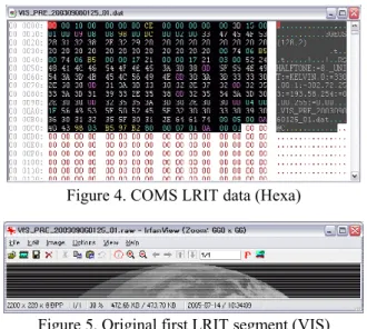
3.3.2 Presentation Layer: The data stream from application layer are divided into 10 image segments with an image segmentation size of 220 lines (current baseline).
The insertion of header records is also performed in presentation layer. The output of presentation layer is called as LRIT_Data and these are transferred into session layer.
Figure 4. COMS LRIT data (Hexa)
Figure 5. Original first LRIT segment (VIS) Figure 4 shows the first image segment of 10 segments divided from VIS channel data. The part in black box are indicating header data and remained part are image data
3 in hexa format. Figure 5 shows the first image segment of
VIS channel generated at the presentation layer.
3.3.3 Session Layer: The session layer includes the definition of the compression and encryption to LRIT _Data files.In this test, the JPEG lossy compression was performed to the LRIT_Data with a rate of 30%.
Figure 6. Compressed LRIT segment (VIS) The result image data are shown in Figure 6 and seems to be very close with the original data. The output data of session layer is called as S_PDU and this data unit are transferred into the transport layer.
3.3.4 Transport Layer: The transport layer performs the TP Header generation for each S_PDU received from session layer as shown in Figure 7. The transport files are split into one or more blocks with a size of 8190 bytes.
The final result, TP_PDU, is generated by adding a 6 byte TP_Header and a 2 byte Cyclic Redundancy Check (CRC) into each transport data block.
TP_Header(6 bytes) Data(8190 bytes) CRC(2 bytes)
· Version(3 bits): 0 - Fixed
· Type(1 bits): 0 - Fixed
· Secondary Header Flag(1bit) 1: Header used 0 : Header not used
· APID (11bits)
· Sequence Flag(2 bits) 11: Single data 01 : First segment 00 : Continued segment 10 : Last segement
· Packet Sequence Counter(14 bits)
· Packet Length (16 bits)
Figure 7. TP_PDU format
3.3.5 Network Layer: The functionality of network layer is the generation of a Virtual Channel Identifier (VCID). The VCID is included in VCDU header information at data link and decided by following equation.
VCID = APID / 32 (1) The Application Identifier(APID) is the header infor- mation included in TP_PDU transferred from transport layer and can be defined for COMS LRIT service as following table.
Table 2. APID definition for COMS LRIT service
APID Application 1056 : VIS
1088 : IR2 1120 : IR3 1152 : IR4 1184 : IR5
LRIT application data
1216 : Alpha-numeric text 1248 : Encryption key message 1280 : NWP data
1312 : Binary data
1313 – 2015 Reserved for LRIT
application data 2016 – 2046 Reserved by CCSDS
(not used for LRIT)
2047 Fill packets
3.3.6 Data Link Layer: The data link layer generates the virtual channel data units (VCDU), performs Reed- Solomon coding, data randomization and attachment of synchronisation markers for generating continuous 1024 byte Channel Access Data Unit (CADU).
The 886 byte M_PDU is generated by splitting the TP_PDU from network layer with a size of 884 bytes, attachment of 2 byte M_Header. The M_Header is used to indicate the header position of TP_PDU as shown in Figure 8.
Figure 8. M_PDU Format
The 892 byte VCDU is generated by attaching 6 bytes VC_Header into M_PDU as following.
Figure 9. VCDU Format
For error control, the VCDUs will be attached by 128 byte Reed-Solomon check symbols to form a coded VCDU (CVCDU). The randomization and attachment of synchronization marker (0x1ACFFC1D) together with the CVCDU create the final data format, channel access data unit (CADU) of 1024 bytes length as shown in Figure 9.
Figure 10. CADU Format
Figure 11 shows the CADU, final result data of data link layer.
Figure 11. CADU data (Hexa)
4 4. VERIFICATION OF COMS LRIT TRIAL DATA
The LRIT user reception station, Small scale Data Utilization System(SDUS), was used to verify the generated COMS LRIT trail data.
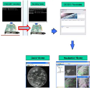
For this test, one sending system performs the generation of LRIT trail data and transmits them into the SDUS instead of the COMS ground station as shown in Figure 12. The SDUS, one receiving system, process received LRIT to restore image data using process referred in section 3 in the reverse direction.
Figure 12 shows the processing diagram for LRIT trial data and result image data. We could verify the COMS LRIT trial data generation and restoration procedure with this simulation test.
Figure 12. The processing diagram to restore the image data from COMS LRIT trail data
5. CONCLUSION
This paper described the COMS LRIT trail data generation procedure at sending system and verification test at receiving system for COMS user dissemination service of MI observation data.
With developing the COMS LRIT trial data generation and restoration software, we could acquire large experience in developing meteorological observation data processing system and user data generation system which are necessary for meteorological satellite systems. These experiences will be beneficial for further developing image data receiving and processing system of meteorological satellite systems.
References from Literature:
[1] CGSM, August 1999. LRIT/HRIT Global Specific- ation, Rev 2.6.
[2] KARI, April 2005, COMS LRIT Specification.
[3] ISO. Information processing systems - open systems interconnection - basic reference model, ISO standard
7498-1.
References from websites:
[4] CCSDS. Advanced Orbiting Systems, Networks and Data Links: Architectural Specification, CCSDS recom- mendation 701.0-B2, Blue Book.
http://ccsds.org/blue_books.html
![Table 1. LRIT OSI Layer Functionality[1]](https://thumb-ap.123doks.com/thumbv2/123dokinfo/5197898.604971/1.892.461.805.881.1149/table-lrit-osi-layer-functionality.webp)