상사 모델과 전산 수치 해석을 이용한 diffuser/nozzle pump 의 정상 상태에 대한 연구
박 성 훈
†
· 고 상 근*
Analysis of the micro diffuser/nozzle pump performance of steady states using similitude model and simulations
Sung Hoon, Park and Kauh, S. Ken
Key Words :
Valve-less pump(밸브리스 펌프), computational fluid dynamics(전산수치해석), similarity model(상사모델), orthogonal array(직교배열표)Abstract
Recently, as the semiconductor production technology develops, there has been growing interest in the cooling system using micro fluid pump. Among the various types of micro fluid pump, the valve-less diffuser/nozzle has been extensively studied in recent years. However, the flat-walled diffuser/nozzle flow has not been clearly looked into due to its non-linear characteristics. In this paper, the flow characteristics of the flat-walled diffuser/nozzle have been analyzed using similitude model and simulations. Similitude models are designed so that the flow pattern is same as that of 1/10 scale flow by using high viscous fluid as working fluid. The results are compared to the simulations. It is shown that the flow characteristics of 2D simulation are different from 3D simulations at high Re region, and the measured pump efficiency is highly dependent on the pressure difference as well as the channel geometry. From these results, the desirable conditions for the efficient pump is discussed.
1. Introduction
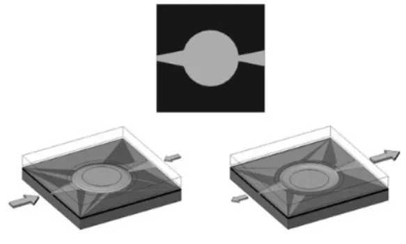
Recently, various kinds of the micro fluid pumps have been proposed. As the micro fluid actuator can control the fluid flow that macro scale pump cannot control, the applications to a various kinds of areas – electronics, mechanics, biology, etc. - are expected. Diffuser/nozzle fluid pump is one of them and has been studied by many articles [5, 7, 10, 12], where the differences in the flow resistance between diffuser and nozzle as a flow generation force have been used (Fig. 1). As this type of fluid pump does not have a mechanically moving valve, it has advantages compared to the other fluid pump methods.
Several types of the diffuser pump designs have been
experimented. For the actuation force of fluid, electrostatic force [10], electro-magnetic force [18], piezoelectric force [19] and thermally expanding bubble [14] has been used. The structure is mainly micro- machined, but the other materials –such as Printed Circuit Board - based pump [11, 17] also has been presented. The analysis of diffuser and nozzle pump using numerical simulations also has been made for different geometries and dimensions [7.12.16]
To understand and improve the diffuser/nozzle pump system, it is important to analyze the flow characteristics of diffuser/nozzle channel flow at different conditions.
The efficiency of diffuser/nozzle fluid pump is highly dependent on geometry which includes not only the diffuser/nozzle channel angle, but also the shape of the channel inlet region and the length of the diffuser element. As the flow boundary conditions change, the operation of the pump becomes significantly different.
As it is difficult to express the performance of diffuser by a simple analytic solution, the design relies on the experimental results, simplified theories and numerical simulations. The difficulty is that the information about diffuser is mainly conical and pyramidal shape, [1] and that the data about plat-walled diffuser which are of
† Department of Mechanical and Aerospace Engineering, Seoul National University
E-mail : [email protected]
TEL : (02)880-1650 FAX : (02)883-0179
*
Department of Mechanical and Aerospace Engineering, Seoul National Universityconcern in this work are not well known at other literatures. [7]
In this paper, the characteristics of the diffuser flow and the nozzle flow is analyzed using Navier-Stokes equation in divergent/convergent channel, and compared with the simulation and experiment results. Two-dimensional simulations of the diffuser element with flipped inlet are conducted changing the diffuser length and the opening angle, according to the pressure boundary condition
∆P=1~105 Pa. Then the results are compared with three- dimensional simulation in which various diffuser designs are compared according to the simple form of an orthogonal array. The pressure boundary condition was used because the diffuser and the nozzle channel are under same pressure difference, not under velocity conditions during pump operation. The ratio of the mass flow rate of the diffuser and nozzle was used as the parameter of the diffuser efficiency, and the feasibility of using this is showed by the formulas and the comparison with the other experiment. The velocity profiles at different pressure boundary condition were calculated and the existence of the asymmetric stall region at the diffuser flow is observed.
Beyond the analysis of the mass flow rate, the unsteady property of diffuser was also studied using velocity profiles and the entrance length. The known characteristics about the entry channel flow were considered with the velocity profile along the channel length direction. From these considerations and the criterion of the exact solution, the range of unsteady region at the diffuser channel and its effect to the performance of diffuser elements is discussed.
Fig. 1
The operation principle of the diffuser/nozzle pump
2. The analysis of the flow in divergent and convergent flow
A flow in diffuser channel is divided by four regions according to its characteristics, which are steady viscous flow, transitory stall flow, steady bi-stable stall flow and jet flow as the flow velocity increases [4]. If the stall occurs, the pressure recovery of diffuser reduces, due to the adverse pressure gradient at the wall boundary region, and that makes flow resistance increase. In nozzle flow, the velocity gradient at wall increases monotonously.
From these change of the velocity gradient at wall, it is
predicted that the difference in flow resistance at the wall between diffuser and nozzle flow will be maximized around the region where the stall at wall occurs in steady viscous flow region. As can be seen by the numerical simulation results, stall at a diffuser wall does not always occur in the same pattern. It may appear asymmetrically at rear part of the channel, due to the unsteadiness of flow.
By solving continuity and Navier-Stokes equation of steady two-dimensional flow in a convergent and divergent channel, the flow pattern of diffuser/nozzle flow is studied. Using the velocity profile obtained here the condition of stall occurrence can be estimated approximately. The velocity profile in diffuser channel shows that the adverse velocity profile and the asymmetric stall occur at different conditions. [2, 3] The governing equations in the divegent/convergent channel are summarized like
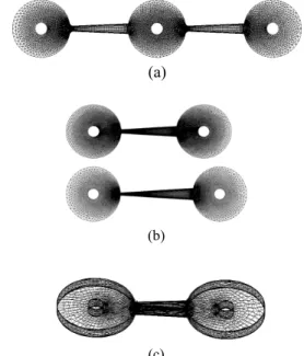
Fig. 2
The velocity profile of divergent and convergent channel flow
Solving (2) using elliptic integral form of differential equation, f distribution for both divergent and convergent channel is obtained. [Fig. 2] In a convergent flow, the f gradient at wall increases as f(0) increases. While in a divergent flow, the f gradient at the wall decreases as f(0) or α increases, until it becomes zero. When f(0) becomes larger, purely divergent flow is impossible and an adverse velocity gradient occurs at some point of the diffuser wall. If f(0) is larger than this value, at certain value of f(0), it does not converge and have more than two solutions. This agrees with the pressure recovery profile which decreases at stall region [4]. The criterions for the purely divergent flow (4), and for the only one solution of the velocity profile (5) in the diverging flow channel is expressed as follows. [3]
It is thought that when the separation occurs the criterion (5) is no longer valid. As the symmetry of the velocity profile, the asymmetric stall cannot be expressed by this solution. But this criterion can still be used as a parameter to predict the region where the asymmetrical stall may occur in two-dimensional diffuser geometry.
3. Simulations and Diffuser Efficiency
In a diffuser/nozzle fluid pump which generates one- way direction fluid flow, the entrance region and the exit region is generally inevitable due to its geometry restriction. To analyze both the diffuser/nozzle effect and the entrance/exit effects, the pressure loss coefficients have been used in the previous studies [7, 12]. But because the known loss coefficients are most for three- dimensional conical & flat-walled diffusers, and the values are highly dependent on the diffuser shape(including inlet/outlet area ratio, divergence angle, slenderness, Reynolds number, inlet boundary-layer blockage factor, aspect ratio, etc[1]), it is difficult to find appropriate coefficients. [7] In this study, the two- dimensional and three-dimensional numerical simulations were conducted in both the entrance and the exit regions by changing diffuser/nozzle shapes and pressure difference between inlet and outlet boundary region to understand the flow in the diffuser/nozzle pair.
3.1 The geometry for simulations
The diffuser geometry for simulation is designed considering the limit of the length and the width of a diffuser element. When the average width of the diffuser element is fixed, the opening angle α has to be smaller than , where d is the average width and L is the length of diffuser. And widening the outlet width may generate a flow separation at the low pressure difference, which reduces the pressure recovery coefficients, and cause the flow resistance to increase [1]. The diffuser elements of the average channel width d=200µm, the channel length L=1500µm and the opening angle α=5°, 7°, 9° are designed. The flip of the inlet can reduce flow resistance remarkably, while the flip of the exit does not.
The flip of r=2d, which is known to be the most efficient at the diffuser flow [1], is made at the inlet region.
The diffuser/nozzle pump is simplified to a two- dimensional geometry [Fig. 3]. The center circle represents the fluid chamber which gives force to working fluid, the left small circle is flow inlet and right small circle flow outlet. By setting the pressure difference boundary condition between the center small circle and the flow inlet/outlet, it can represent the operation of the diffuser/nozzle pump flow. It is thought that the center circle radius can affect the flow. However, we found that changing the radius does not show much difference on the channel flow characteristics. This is because the pressure in center chamber remains almost constant compared to the pressure variation at the
diffuser channel. The diffusers are simulated using the geometry like [Fig. 4]. This geometry shows almost same flow rate as that of diffuser/nozzle pair shape.
The grid size is fine near the entry and exit region and the wall of the channel because the velocity gradient is large at these regions. The meshed diffuser element contains 37826 cells, 62154 interior faces and 25247 nodes when α=7° and L=1500µm. Numerical simulations are done using Computational Fluid Dynamics program Fluent 6.1.22 on the two-dimensional, double-precision, segregated, laminar condition.
In this study, the mass flow rate was calculated according to the pressure difference, ∆P=1~105Pa, and the opening angle α. The velocity profiles according to the pressure difference and the location of diffuser were also calculated and compared with analytic solutions.
(a)
(b)
(c)
Fig. 3 (a)
Diffuser/Nozzle pump geometry for 2D simulation (b) Diffuser element geometry for simulation for channel length
L=1500µm, 2000µm (c) Diffuser element geometry for 3D simulation for channel length L=1500µm, α=5°, height=100µm
3.2 Efficiency of Diffuser element
In the previous researches, the loss coefficient was used to estimate the efficiency of the diffuser element [6, 12, 16]. In this study, the ratio of the mass flow rate was used as the parameter of the diffuser efficiency, for the simplicity of the calculation. When ξ is the pressure loss coefficient and is the mean velocity in the diffuser inlet, the relation between ∆P and ξ is expressed as
And the diffuser element efficiency η is defined as
When is the area of throat, the relation between and is
From (7) and (8), the relation between mass flow rate and diffuser efficiency η is obtained.
is the ratio of diffuser/nozzle flow mass rate.
It is shown that this value also can be used as a parameter of the efficiency of the diffuser element. By comparing with previously measured diffuser efficiency with the ratio of flow rate at the simulation results, the relation (9) proved to be feasible [Fig. 6].
4. Experiment
The experiments was done using the similarity analysis. To make similar velocity profile at macro scale channel, high viscous fluid KF-96-100CS is used as a working fluid. KF-96-100CS has a kinematic viscosity 100times, and similar density compared to the liquid- water. With 10 times large-sized channel and 100 times larger pressure difference, the similar profile of velocity can be obtained. In this experiment, micro channel characteristics which are important at some circumstances [20] are neglected.
The test part channels are made using acrylic plate which is easily fabricated by laser. The dimensional parameters of the diffuser channel are channel opening angle α=7°, channel length L=15mm, channel height h=1.3mm and average channel width d=2mm. The pressure difference ∆P which is applied between the pressure vessel and the free air is 20~300kPa, which is thought to be similar to the 1/10 scale micro channel flow at ∆P=200~3kPa.
Fig. 4
Experiment Setting
5. Results
5.1 Two-dimensional simulation
The steady state mass flow rate of the diffuse/nozzle element and its ratio was calculated at the pressure difference boundary conditions, ∆P=1~105 Pa. The diffuser geometry has a flipped inlet and a sharp outlet, with the average diffuser width d=200µm, angle α=5°, 7°, 9° [Fig. 5(a)] and diffuser length L=1500µm, 2000µm. [Fig.5(b)]
The calculated results show that, at the low pressure difference region the flow rate of diffuser and nozzle are similar (
)
. As the pressure difference increases, the ratio of mass flow rate begins to increase (A) and at a certain ∆P, it decreases (B). Before region A, it seems as if the flow velocity is too slow to have some different velocity gradient between the diffuser and the nozzle.Between A and B, the flow rate of the diffuser increases more rapidly than at the nozzle flow. It agrees with the velocity gradient of the exact solution in a diverging/converging channel (chap. 2), which indicates that as the flow rate increases, the difference in velocity gradient at the diverging/converging channel wall increases rapidly. In region B, the slope of the diffuser mass flow does not increase as much as the other regions, this makes the diffuser efficiency drop below one. At this region, the asymmetric stall is observed at velocity profile. This implies that asymmetric stall is the main reason for the efficiency decrease at 2D diffuser flow.
(a)
(b)
Fig. 5
Comparison of the diffuser and nozzle flow rate ratio at (a) different opening angle α=5˚, 7˚, 9˚ and (b)
different channel length L=1500µm, 2000µm at α=7˚
Fig. 6
Comparison of the diffuser efficiency between the other paper [12] and this work, at ∆P=10
4~10
6Pa. when
symmetrical velocity profile is assumed
5.2 Three-dimensional simulation
The asymmetric stall – this may be interpreted as a turbulent flow - which causes diffuser efficiency drop at 2D simulation does not dominant at 3D simulation.
Instead, the efficiency begins to decrease slowly and unstably at the region where the unsteady turbulent flow is thought to be dominant. Turbulent flow region in diffuser flow is researched by many articles but the exact criterion of the transition cannot be found. Owing to this reason, the diffuser efficiencies were calculated at the maximum pressure difference
∆P=10
3Pa
where the laminar flow is reasonably dominant for test diffuser dimensions.The following components represent the diffuser geometry [Fig. 3(c)] – which include diffuser channel length L, opening angle α, channel depth h and average channel width d. Because of the geometrical restriction, the levels of each geometry can be reduced like [Table.
1] at d=200µm. As can be seen from the results of [Table.
2], channel depth h has dominant effect on the diffuser efficiency. And in this region of levels, the short diffuser with wide angle seems to be more efficient.
L α h
Level 1 1000µm 5° 100µm
Level 2 2000µm 9° 200µm
Table. 1
Definition of levels when d=200µm
no L α h Efficiency
1
1 1 1 1.031
2
1 2 2 1.142
3
2 1 2 1.133
4
2 2 1 1.033
Level L α h
1 2.173 2.164 2.064
2 2.166 2.174 2.274
Effect 0.007 -0.011 -0.210
Table. 2Orthogonal Array for ∆P=1000Pa and the
effects of diffuser dimensions according to different levels
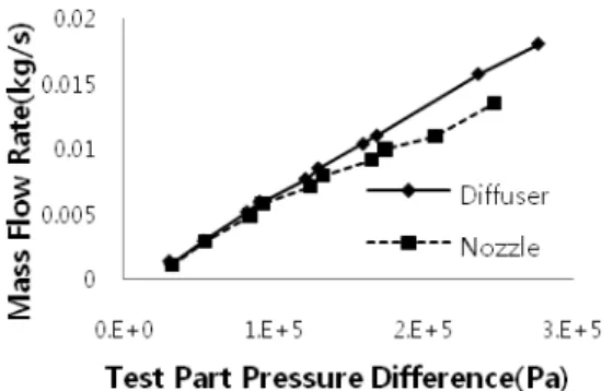
5.3 Experiment
The experiment at the diffuser shows that the efficiency at low Re region is relatively small but does exists, and increases as the pressure difference increases.
It can be seen that the pressure differences where the efficiency increases and where it becomes unstable is almost 100times of 2D simulation results.[Fig. 7]
Fig. 7
Diffuser/nozzle mass flow rate at 100times large similitude model experiment
6. Discussion
The 2D and 3D diffuser/nozzle pump model was simulated and experimented using similitude model at several geometries and different pressure difference.
1. As a parameter of the efficiency of a diffuser element, the ratio of the mass flow rate between the diffuser and the nozzle at same pressure difference was used.
2. From the solutions of the continuity equation and Navier-Stokes equation in the diverging/converging channel flow, the diffuser efficiency according to the flow rate was roughly predicted, which shows the similar tendencies with the results of the numerical simulations and experiments.
3. Using the results of the numerical simulations, it is shown that the diffuser efficiency has different characteristics according to the opening angle, diffuser length and the different pressure inputs. The efficiency of the diffuser element was not large at low pressure differences, and decreased at high pressure differences [Fig. 5]. As α or d is large, the flow unsteadiness is likely to occur at the lower pressure difference.
4. Without regarding the effect of unsteadiness flow, the influence of diffuser geometry to the efficiency was evaluated at the presumably laminar region using orthogonal array. This results shows that the large channel depth, the large opening angle and the short channel length improves the diffuser efficiency. Among them the channel depth shows important effect.
Orthogonal Array with more components like the scale of the diffusers will be researched, and the similitude experiment will be executed at the several regions and geometries.
Reference
[1] Fran M. White., 1994, “Fluid Mechanics 3rd ed.”
McGRAW-HILL International Editions
[2] I.G. Currie., 1993, “Fundamental Mechanics of Fluids 2nd ed.” McGRAW-HILL International Editions, p236-239
[3] G.K.Batchelor, F.R.S., 1967, “An Introduction to Fluid Dynamics”, Cambridge University Press, p294- 302
[4] E.M. Greitzer, C.S. Tan, M.B. Graf., 2004,
“Internal Flow, Concepts and Applications”, Cambridge University Press, p166-170
[5] E. Stemme and G. Stemme, 1993, “A Valveless Diffuser/Nozzle-Based Fluid Pumps”, Sensors and Actuators A, Vol. 39, pp.159-167
[6] A. Olsson, G. Stemme, and E. Stemme, 1996,
“Micromachined Diffuser/Nozzle Elements for Valve- Less Pumps”, IEEE MEMS ’96, pp. 378-383
[7] T. Gerlach, 1996, “Fundamentals of Dynamic Flux Rectification as the Basis of Valve-Less Dynamic Micropumps”, Micro System Technologies’96, pp.445- 450
[8] A. Olsson, G. Stemme and E. Stemme, 1996,
“Micromachined diffuser/nozzle elements for valve-less pumps”, Proceedings of the IEEE Micro Electro Mechanical Systems (MEMS), p378-383
[9] A. Olsson, P. Enoksson, G. Stemme, and E.
Stemme, 1997, “Micromachined Flat-Walled Valveless Diffuser Pumps”, Journal of microelectromechanical systems, vol. 6, no. 2
[10] Popescu, Dan S.; Lerch, Philippe; Dunare, Camelia; Dascalu, Dan, 1997, “Modelling and optimization for an electrostatic actuation of a valveless micropump using a silicon buckled membrane”, Proceedings of the International Semiconductor Conference, CAS, v 1, p 157-160
[11] Tobias Merkel, Michael Graeber, Lienhard Pagel., 1999, ”A new technology for fluidic micorsystems based on PCB technology”, Sensor and Actuators 77, 98-105
[12] A. Olsson, G. Stemme, and E. Stemme, 2000,
“Numerical and experimental studies of flat-walled diffuser elements for valve-less micropumps”, Sensors and Actuators, A:Physical, v 84, n 1, p165-175
[13] Ansgar Wego, Stefan Fichter and Liehard Pagel, 2001, “Fluidic Microsystems based on printed circuit board technology”, Journal of Micromechanics and microengineering, 11, 528-531
[14] Jr-Hung Tsai and Liwei Lin, 2001, “A Thermal Bubble Actuated Micro Nozzle-Diffuser Pump”, Proceedings of the IEEE Micro Electro Mechanical Systems (MEMS), p409-412
[15] R. M. Sadri, J. M. Floryam.,2002, ”Accurate Evaluation of the Loss Coefficient and the Entrance Length of the Inlet Region of a Channel”, Journal of Fluids Engineering, Transactions of the ASME, v 124, p 685-693
[16] Vishal Singhal, Suresh V. Garimella and Jayathi Y. Murthy, 2004, “Low Reynolds number flow through nozzle-diffuser elements in valveless micropumps”, Sensors and Actuators A: Physical, p226-235
[17] Eniko T. Enikov, Kalin Lazrov, 2003, “PCB- integrated metallic thermal micro-actuators”, Sensors and Actuators A 105, p76-82
[18] Y Su, W Chen, F Cui and W Zhang, 2005,
“Analysis and Fabrication Process of an Electro- Magnetically Actuated Valveless Micropump With Two Parallel Flexible Diaphragms”, Proceedings of the Institution of Mechanical Engineers, Part C: Journal of Mechanical Engineering Science, Volume 219, Number 9, p1007-1014
[19] Nguyen, Thanh-Tung; Goo, Nam Seo, 2006, “A novel PDMS valveless micropump with a circular lightweight piezo-composite actuator”, Key Engineering Materials, v 326-328 I, p 245-248
[20] G.Hetsroni, A. Mosyak, E. Pogrebnyak, L.P.
Yarin, 2005, “Fluid flow in micro-channels”, International Journal of Heat and Mass Transfer 48 1982-1998
![Fig. 6 Comparison of the diffuser efficiency between the other paper [12] and this work, at ∆P=10 4 ~10 6 Pa](https://thumb-ap.123doks.com/thumbv2/123dokinfo/5201310.353071/4.892.504.780.956.1115/fig-comparison-diffuser-efficiency-paper-work-p-pa.webp)