Two-pupil 광학 스캐닝 기술과 PAL-공간변조기를 이용한 패턴 인식
Pattern Recognition using Two-pupil Optical Scanning Technique and PAL-Spatial Light Modulator
도규봉*, 김관인*, 김명수*
Kyu-Bong Doh*, Kwan-In Kim* and Myeong-Soo Kim*
요 약
본 논문에서 우리는 PAL-공간변조기를 사용한 Two-pupil 광학 스캐닝 기술에 의하여 실시간 JTC 상관 광 시스템을 수행할 수 있음을 보여주고자 한다. 광학적 addressing(Optical addressing)은 빛에 민감한
층, 즉 액체 크리스털을 따라 전기장을 조절하는 얍은 층에 의하여 성취되었다. 제안된 기술은 광학적 Twin-pupil 헤테로다인 스캐닝(heterodyne scanning)에 근거하고 있으며, 이 기법은 Fourier 평면에 위치한 광 공간변조기와는 독립적으로 작용한다. 우리는 본 기술의 이론적 근거를 개발하고, 목표이미지와 참조이미지 사이의 상관관계를 실험적으로 평가함으로서 본 기술의 성능을 평가하였다.
Abstract
We demonstrate experimentally that the method of Two-pupil optical scanning technique with PAL-spatial light modulator is capable of performing real-time joint transform correlation(JTC) optical system. Optical addressing is achieved by the use of a photosensitive layer of which controls the electric field across the liquid crystal. The demonstrated technique is based on two-pupil optical heterodyne scanning. The method is independent of a spatial light modulator (SLM) in the Fourier plane. We develop the theory of the technique and evaluate a performance of the method by experimentally estimating the correlation between the target image and the reference image.
Key words : Spatial light modulator, Joint transform correlation, Two-pupil, Pattern recognition.
* 한국항공대학교 항공전자및정보통신공학부(School of Electronics and Telecommunication Engineering, Korea Aerospace University) ‧ 제1저자 (First Author) : 도규봉
‧ 투고일자 : 2008년 10월 1일
‧ 심사(수정)일자 : 2008년 10월 2일 (수정일자 : 2008년 10월 24일) ‧ 게재일자 : 2008년 12월 30일
I. Introduction
The main objective of this paper is to experiment two-pupil scanning technique for optical image recognition of the object using Parallel Aligned Liquid crystal Spatial Light Modulator (PAL-SLM). The
correlation of two images is one of the most important mathematical operations in image processing and pattern recognitions. As the image become more and more complex and large in size, the calculation becomes time consuming for a digital computer. Optical processing is an alternative to digital processing because it offers
in the areas of medical imaging and recognition, robotic visions, data acquisition and processing, and optical remote sensing.
A key operation to the achievement of optical image recognition is optical correlation, i.e., an optical technique capable of performing correlation of a reference object and a target object to be recognized. Research in pattern recognition has its root in the 1960’s and it has been rejuvenated in past decades because of the advancement of the development of the display devices[1-3, 4-6].
Optical image processors have attracted considerable attention because of their ability to perform a large number of valuable operations at extremely high speeds.
Optical correlation-based recognition algorithms have been proposed for use in a wide range of application [7-16]. One of the most important function of an optical processor is the detection of a given reference pattern within the input data. The implementation of a real-time joint transform image correlators generally requires two spatial light modulators. One is employed at the input plane through which the input and reference image are entered. The other is inserted at the Fourier plane to read out the intensity of the interference between the Fourier transform of two signals. Parallel optical processing by use of frequency domain architecture is faster, but often lacks flexibility and accuracy. Scanning optical processing is fast, accurate, and flexible [17].
The paper is organized as follow. In section II we briefly review the background and the principles of two-pupil optical scanning technique. A simplified theory of its proposed implementation is also given in Section II. In section III. we give technical details of the experimental setup, and the experimental results are discussed, followed by summary and concluding remarks in section IV.
Scanning Technique
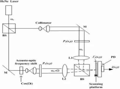
We briefly review the theory of two-pupil optical scanning technique [18-19] and its system used to perform a real-time correlation operation. In incoherent image processing, intensity quantities are manipulated, hence the most severe limitation of incoherent image processing has been its inability to synthesize bipolar point-spread function (PSF’s). The important development of incoherent image processing has therefore been the introduction of dual-channel processing has been its inability to synthesize bipolar point-spread function (PSF’s). The important development of incoherent image processing has therefore been the introduction of dual-channel processing, commonly known as two-pupil processing. The methods of two-pupil synthesis utilize two parallel channels and realize the negative part of the PSF either by a direct difference of illumination or by an interferometric interaction of two pupils. Two-pupil heterodyne scanning technique has been used in a wide range of application such as incoherent image processing [18,20,21], complex holographic recording[22], 3-D microscopy[23,24], optical remote sensing[25], and optical cryptography[26]. A typical two-pupil heterodyne optical scanning system is shown in Figure 1. Beam splitters BS and mirrors M form a Mach-Zehnder interferometer. A collimated laser at a temporal frequency
is used to illuminate the pupil . The other pupil, , is illuminated by a laser of temporal frequency . The laser’s temporal frequency offset of is introduced by an acousto-optic frequency shifter, as shown in Figure 1. The two pupils are located at the front focal planes of lenses L1 and L2, both with a focal length . The two pupils are then combined by beam splitter BS to focus the light onto the 2D x-y scanning platform, which are located on the back focal plane of lenses L1 and L2. The combined optical scanning field is used to 2-D raster scan over an object of amplitude distribution , located at scanning
Fig. 1. Two-pupil optical heterodyne scanning system.
platform. Photo-detector collect all the transmitted light and an electronic bandpass filter tuned at the heterodyne frequency gives a scanned and processed current as output. The beam splitter BS1, as shown in Fig. 1, combines the fields from the two arms of the interferometer to give the total field distribution given by:
exp
exp
(1)
In Equation (1), is the field distribution in the back focal plane of lenses L1 and L2 and is given, aside from some nonessential constants and a phase factor, by
′′exp
′ ′′′
(2)
where denotes the optical Fourier transform
operation and is defined as
exp
with and denoting the spatial frequencies and with the uppercase function U denoting the transform of the lowercase function u. The combined total optical field (Equation (1)), or scanning pattern, is used to scan an object amplitude transparency as shown in Fig. 1. The photo-detector, which responds to the incident intensity of the optical transmitted field or scattered field, generates a current that is given by
exp
exp
× ′ ′′
(3)
Note that the integration is over the area A of the
the instantaneous position of the scanning pattern, and that the shifted coordinates of represent the action of scanning. The heterodyne current at the temporal frequency , after a band-pass filter tuned at the frequency , becomes
Ω
′
′
′
′
(4)
× ′ ′′′exp
Where we adopted the convention for phasors as
exp. Equation (4) can be written as
exp (5)
Where
Ω
′
′
′
′
× ′ ′′′
is the output phasor and denotes the amplitude and the phase information of the heterodyne current.
The amplitude and the phase information constitute the scanned and the processed version of the object . Defining the correlation operation as
⊗
′′ ′ ′′′(6)
We can now rewrite the output phasor as
⊗
(7)
Note that the optical scanning system under consideration can process the intensity distribution of the object being scanned.
Fig. 2 Block diagram of Real-time two-pupil heterodyning JTC system with PAL-SLM.
(a) (b) Fig. 3 Fingerprints used in the tests:
(a) The authorized fingerprint.
(b) The unauthorized finger print.
(a)
(b)
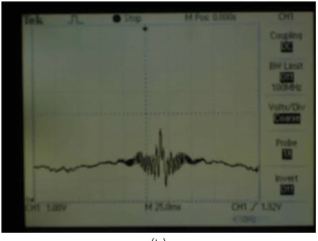
Fig. 4 Correlation results for the verification.
(a) Correlation result for authorized input.
(b) Correlation result for unauthorized input.
Ⅲ. Experimental Setup and Results
Fig. 2 is a block diagram of the real-time joint-transform correlators. A laser beam
generated by a He-Ne laser entered acousto-optic frequency shifter to produce two beams (the zeroth-order beam and the first-order beam) operating at frequencies and , respectively, where is the frequency of the laser light. The acousto-optic frequency modulator operates in the Bragg regime at sound frequency 40 MHz. After a 3× beam expender, these beams are then collimated by lens L1 with 5㎝ focal length. The zeroth-order beam and first-order beam are incident on the liquid crystal side of PAL-SLM through the beam splitter. The PAL-SLM has a structure in which amorphous silicon, a dielectric mirror, and liquid crystal are enclosed by two glass substrates with transparent electrodes. A write light is irradiated on the amorphous silicon side, and a readout light is irradiated on the liquid crystal side. The input images (target and reference images) are placed in the amorphous silicon side. When a write light is applied, the readout light is modulated by movement of the liquid crystal molecules. Now the readout light of the zeroth-order and first-order beams which contains information of and respectively are
reentered into beam splitter and then combined at the beam splitter 2 projected through the 1-d scanner along the x direction. The combined beams are focused onto the chirp grating located at the back focal plane of lens L2. Lens L3 is used to collect all the light onto the photo-detector. The output of the photo-detector is then sent to the lock-in amplifier to give the rock-in current.
The correlation of the two input pattern will be displayed on the real-time display. The goal of the experiment is to illustrate the correlation of between the target and reference images discussed in Section 2. Experiments with different reference objects and target objects have been performed. There are two possible ways to demonstrate the signal. The first is to use a lock-in amplifier and the second is to collect the entire signal and filter it in Fourier space. The first method was chosen for the results shown in this section. To compare the results between different experiments, all the system parameters, such as the power of the laser source, the scan speed of x scanner, the time constant and sensitivity of the lock-in amplifier, and the voltage scale and time scale of the oscilloscope are set to the same values throughout these experiments. Fig. 3 shows fingerprints of dimensions of approximately 8 mm × 8 mm to be used in the experiment. The fingerprint shown in Fig.
3(a) is chosen to be authentic, and the fingerprint shown in Fig. 3(b) is considered to be unauthorized biometric image to be rejected. The front focal plane of lens L2 is 100 centimeters. The two patterns are separated by
≈ millimeters, which gives ≈
cycle/mm. Experiment with different input images and reference image have been implemented. In Fig. 4, the cross correlation between input images and reference image are presented. Fig. 4 (a) illustrates the output correlation intensity for verification when an authentic reference fingerprint and an authorized fingerprint are used. A sharp and strong output peak for the input is obtained. Fig.4 (b) shows the output correlation for verification when an authentic reference fingerprint and an unauthorized fingerprint are used. Time scale is 25.0
Fig. 6 shows the pattern of the chirp grating used, it is basically a function of cos, that is, a set of dark lines of varying separations printed on a glass substrate.
The grating frequency ranges from 1 cycle/mm to 25 cycle/mm.
Ⅳ. Concluding Remarks
We have experimented optical scanning technique for optical image recognition of the object using Parallel-Aligned-nematic-Liquid- crystal Spatial Light Modulator (PAL-SLM). An optically addressed PAL-SLM is developed for applications in optical information processing and interferometry. The device uses the electro-optical characteristics of a parallel-aligned nematic liquid-crystal layer to give a large phase-dynamic range with minimal effect on polarization or intensity. Optical addressing is achieved by the use of a photosensitive layer of , which controls the electric field across the liquid crystal. Optical Scanning Technique was invented as an application of the two-pupil interaction schemes, which are unique in extending the incoherent optical processing realm to operations requiring bipolar, complex, point-spread functions. We have also shown that the method of Two-pupil optical scanning technique is capable of performing real-time joint transform correlation (JTC) optical system. The demonstrated technique is based on two-pupil optical heterodyne scanning. We also show that it is possible to achieve real-time JTC in which the system does not require an SLM at the Fourier plane as in other real-time JTC systems. The potential advantages of the method include the independence of a spatial light modulator (SLM) in the Fourier plane which has limitations for applying to robust systems and the capture of correlation for 3D objects by using 2D scan method instead of 1D scan which used in this experiment. The system is a hybrid processing combined of optical and
we have shown that real-time joint-transform correlators without the use of any two-dimensional spatial light modulator located at the Fourier plane. It does not suffer from the drawbacks with the conventional real-time system. The principles of the method have been described, and its feasibility has been experiment.
References
[1] A. VanderLufg, “Signal detection by complex spatial filter,” IEEE Trans. Inf. Theory IT-10, 139-146, 1964.
[2] C. S. Weaver and J. W. Goodman, “A technique for optically convolving two functions,” Appl. Opt. 5, 1248-1249, 1966
[3] J. E. Rau, “Detection of Differences in Real Distributions,” J. Opt. Soc. Am. 56, 1490, 1966.
[4] Special issue on Advances in Recognition Technique, Opt Eng 37(1), 1998.
[5] Special issue on Spatial Light Modulators, Research Development and Application, Appl. Opt. 37(32), 1998
[6] N. Mukohzaka, N. Yosha, H. Toyoda, Y. Kobayashi, and T. Hara, “Diffraction efficiency analysis of a parallel-aligned nematic-liquid-crystal spatial light modulator,” Appl. Opt. 33, 2804-2811, 1994 [7] B. Javidi, “Nonlinear joint power spectrum based
optical correlation,” Appl. Opt. 28, 2358-2367, 1989 [8] W. Hahn and D. Flannery, “Basic design elements
of the binary joint transform correlator and selected optimization technique,” Opt. Eng. 31, 896-905, 1992 [9] J. Horner, “Metrics for assessing pattern-recognition
performance,” Appl. Opt. 31, 165-166, 1992 [10] R. Kuranov, V. Sapozhnikova, D. Prough, I.
Cicenaite, and R. Esenaliev, “Correlation between optical coherence tomography images and histology of pigskin,” Appl. Opt. 46, 1782-1786, 2007 [11] M. Alkanhal and B. Kumarn, “Polynomial distance
classifier correlation filter for pattern recognition,”
Appl. Opt. 42, 4688-4708, 2003
[12] B. Kumar, A. Mahalanobis, and A. Takessian,
“Optimal tradeoff circular harmonic function correlation filter methods providing controlled in-plane rotation,” IEEE Trans. Image Process. 9, 1025-1034, 2000
[13] P. Nisenson and R. A. Sprague, “Real-time optical correlation,” Appl. Opt. 14, 2602-2606, 1975 [14] F. T. Yu, S. Jutamulia, T. Lin, and D. Gregory,
“Adaptive real-time pattern recognition using a liquid crystal TV based joint transform correlator,” Appl.
Opt. 26, 1370-1372, 1987
[15] G. Lu, Z. Zang, S. Wu, and F. T. Yu,
“Implementation of a non-zero-order joint-transform correlator by use of phase-shifting techniques,”
Appl. Opt. 38, 470-483, 1995
[16] A. Matwyschuk, P. Ambs, and F. Christnacher,
“Targer tracking correlator assisted by a snake-based optical segmentation method,” Opt. Commun. 219, 125-137, 2003
[17] G. Indebetouw, “Scanning optical correlators,” Opt.
Lett. 6,10-12, 1981
[18] T.-C. Poon, “Scanning holography and two- dimensional image processing by acousto-optic two-pupil synthesis,” J. Opt. Soc. Am. A2, 621-627, 1985
[19] T.-C. Poon and Y. Qi, “Novel real-time joint- transform correlation by use of acousto-optic heterodyning,” Appl. Opt. 42, 4663-4669, 2003 [20] A. Lohmann, W. Rhodes, “Two-pupil synthesis of
optical transfer functions,” Appl. Opt. 17, 1145-1151, 1978
[21] J. Mait, “Pupil-function design for complex incoherent spatial filtering,” J. Opt. Soc. Am A 4, 1185-1193, 1987
[22] Kyu. Doh, T.-C. Poon, and G. Indebetouw, “Twin- image noise in optical scanning holography,” Opt.
Eng. 35, 1550-1555, 1996
[23] J. Swoger, M. Martinez-Corral, J. Huisken, and E.
Stelzer, “Optical scanning holography as a technique
for high-resolution three-dimensional biological microscopy,” J. Opt. Soc. Am A, 19, 1910-1918, 2002
[24] G. Indebetouw, A. Maghnouji, and R. Foster,
“Scanning holographic microscopy with transverse resolution exceeding the Rayleigh limit and extended depth of focus,” J. Opt. Soc. Am A, 22, 892-898, 2005
[25] B. Schilling and G. Templeton, “Three-dimensional remote sensing by optical scanning holography,”
Appl. Opt. 40, 5474-5481, 2001
[26] T.-C. Poon, T. Kim, and Kyu Doh, “Optical scanning cryptography for secure wireless transmission,” Appl.
Opt. 42, 6496-6503, 2003
도 규 봉 (都圭峯)
1989년 12월 : Virginia Tech 전기공학 과(학사)
1992년 12월 : Virginia Tech 전기공학 과(석사)
1996년 12월 : Virginia Tech 전기공학 과(박사)
1997년 3월~현재 : 한국항공대학교 항 공전자 및 정보통신공학부 교수
관심분야 : Optical information /image Processing, Optical Security, Optical Fiber Sensor
김 관 인 (金寬仁)
2008년 9월 : 한국항공대학교 정보통신 공학과 학사과정
관심분야 :광통신, 광정보처리
김 명 수 (金明秀)
2008년 9월 : 한국항공대학교 정보통신공 학과 학사과정
관심분야 :광통신, 광정보처리