Journal of Navigation and Port Research International Edition Vol.35, No.4 pp. 299~302, 2011 (ISSN-1598-5725)
DOI : 10.5394/KINPR.2011.35.4.299
- 299 -
Effect of Center Frequency Deviation in Miniaturized CMOS Bandpass Filter
In-Ho Kang*․Shang-Ming Li**․Xin Guan***
* Radio Dept. Korea Maritime University
**,*** Radio Dept. Korea Maritime University
Abstract : In this letter, the effect of quality factor on center frequency deviation in miniaturized coupled line bandpass filter (BPF) with diagonally end-shorted at their opposite sides and lumped capacitors is theoretically analyzed. The miniaturized BPF of a two-stage structure with two types of quality factors in standard CMOS process was designed and manufactured at 5.5 GHz. The die area of BPF was 1.44 × 0.41 mm2. The measured center frequency of BPF with a quality factor of 4.9 was deviated from 5.5 GHz to 4.7 GHz. The one with 14.8 was shifted to 5GHz. The theoretical and measured results validate that quality factor influences the center frequency shift of BPF.
Key words : Center frequency shifts, Quality factor, Shunt resonator, Substrate loss, Bandpass filter, CMOS
* [email protected] 051)410-4422 ** [email protected] 051)410-4919
*** [email protected] 010)5879-0755
1. Introduction
Bandpass filters are essential components in wireless communication circuits. RF transceiver development has been moving toward single-chip implementation, eliminating the discrete elements. Many BPFs have been published by CMOS technology, which has emerged as a viable system-on-a-chip technology that enables the full integration of RF integrated circuits. However, these filters have suffered from inherent losses with silicon substrate and low quality factor [7], [2], [6] (Soorapanth & Wong, 2002 ; Georgescu & Finvers, 2006 ; Mohieldin & Sinencio, 2003).
The miniaturized bandpass filter using diagonally end-shorted at their opposite sides and lumped capacitors showed more promise and a relatively higher quality factor than filters with the spiral inductors [5] (Kang & Zhang, 2009). However, the center frequencies of these filters are inclined to shift to the lower frequency. The greater difference in the center frequency of these filters between simulation and measurement in CMOS fabrication has not been analyzed until now.
In this letter, miniaturized coupled line BPF with a two-stage structure by standard silicon integrated circuits was designed and manufactured at 5.5 GHz. One-layer and six-layer BPFs were implemented for the comparison. The center frequency shifts will be theoretically proven to be caused by transmission losses and quality factors in the lossy distributed inductor of the shunt resonator. These
approaches will be verified by the measurements of BPFs with two types of quality factors.
2. Technology Description
L
0L
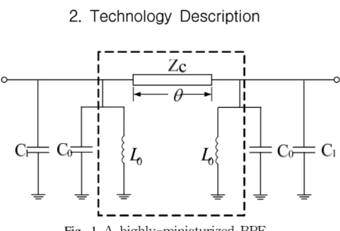
0Fig. 1 A highly-miniaturized BPF
A highly-miniaturized BPF can be implemented using a shunt resonator and a section of high- impedance transmission line [4] (Kang & Shan, 2007), and the structure is shown in Fig. 1. For the ideal BPF, we can set the conductivity of the substrate to zero and transmission line to lossless.
ZC,C1andθ in Fig. 1 are the characteristic impedance of the shortened transmission line, the lumped capacitor, and the electrical length of the shortened line defined in Hitota’s size reduction method [3] (Hirota & Minakawa, 1990). C0andL0are the capacitor and the inductor for the resonance. The resonator in Fig. 1 has a resonance frequency as follows:
Effect of Center Frequency Deviation in Miniaturized CMOS Bandpass Filter
- 300 -
0 0 0
1
wr w
= L C =
(1)
where wo is the center frequency.
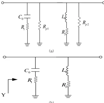
However, the substrate’s loss effect is actually too severe to be ignored as the silicon substrate is inherently lossy and the electrical field which exists in the coupled line circuit on the top plates tends to leak into it. Although the exact equivalent circuit of the distributed inductor is complicated, we assume that the distributed inductor loss of coupled line is mainly due to the series resistance R2,as shown in Fig. 2 (a), the equivalent circuit of the resonator. Because the resistance Rp1 and Rp2 of the parallel part do not change the resonant frequency of shunt resonance, Fig. 2 (b) is the simplified circuit of Fig. 2 (a) for modeling the resonance frequency deviation. For the MIM capacitor, an equivalent series resistance R1exists in the MIM circuit model and a maximum Q of about 80 was reported [1] (Burghartz &
Soyuer, 1996).
C0
(a)
L0
R1
R2
C0
(b)
Fig. 2 Equivalent circuit of the resonator
The resonator in Fig. 2 (b) has the following Y admittance:
( )
( )
2 0
1 0
0 1 0
2 0
2
2 2
2 0 1 0
1 1
1
1
( ) 1
Y R jwL R
jwC
jwC jwR C R jwL
R wL wR C
= +
+ +
− −
= +
+ + (2)
The imaginary part of Eq. (2) equals to zero for resonance,
( )
0 0
2 2 2
2 0 1 0
( ) 1 0
jwL jwC
R wL wR C
− + =
+ + (3)
The resonance frequency is derived from Eq. (3)
2 1
2 2
) ( 1
o o
o o o
r L C RC
L R C
w −
−
= (4)
From Eq. (4), the resonance frequency of the circuit in Fig. 2 (b) using the quality factors is expressed as follows:
2 0
2
1 1
1 1
L r
C
w w Q
Q
−
=
− (5)
where QLis the quality factor of the distributed inductor,
0 0 2 L
Q w L
= R
(6)
QCisthequalityfactoroftheMIMcapacitor,
0 1 0
1 QC
w R C
=
(7)
The corresponding operating resonance frequency ωr in Eq.(5) will be smaller than the center frequency ω0 of the lossless circuit. The deviation of center frequency assumes to be expressed as Δω= ω0- ωr. In Fig. 3, the logarithm of Δω/ω0
versus QL factor is plotted. Three kinds of curves are shown for the case of QC= 40, 60, and 80 as the parameter, respectively. As QC increases, as shown in Fig3, log(Δω/ω0) increases. Usually the deviation of center frequency improves as Q increases. In contrast, this trend is to be notable as not
0 5 10 15 20 25 30 35 40 45 50
-5.0 -4.5 -4.0 -3.5 -3.0 -2.5 -2.0 -1.5 -1.0 -0.5
0
log w w Δ
QL factor Qc=40
Qc=60 Qc=80
Fig. 3 The logarithm of Δω/ω0versus the QLfactor
In-Ho Kang․Shang-Ming Li․Xin Guan
- 301 - to be expected. When QCis equal to QL in Fig. 3, ωr becomes ω0 and log(Δω/ω0) is zero. In case of the QC being lager than QL, ωr becomes larger than ω0. It means that the center frequency starts to be shifted to the higher frequency.
3. Results
To verify the approaches, two kinds of cascade miniaturized coupled line BPFs with one and six layers were considered. First, a one-stage bandpass filter was designed at 5.5 GHz. For the BPF with one layer, a coupled line of 70 electrical length was used. The coupled line width was 20 μ m, the transmission line length was 570 μm and the separation between the two coupled lines of 140 μm was used to provide input/output impedance matching the system impedance Z0 = 50 Ω. The six-layer filter also had a 20 μm line width, 570 μm line length, and 140 μm coupled line separation. Then, two similar one-stage filters with one and six layers were cascaded, respectively. This technology is well explained by [5](Kang & Zhang, 2009). The conductivity of the coupled lines is assumed by 2.4×10⁷Siemens/mand the substrate is lossless for the simulation process.
These filters were fabricated using Magnachips 0.18 μm process with 10 Ω cm bulk silicon substrate and aluminum metal layers. The total die area, including the ground plane surrounding the integrated BPF, was 1440 μm ´ 410 μm. A photograph of the layout is shown in Fig. 4.
Fig. 4 Photograph of the fabricated bandpass filter.
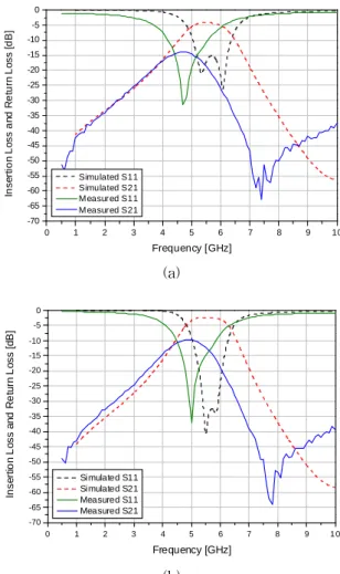
In Fig. 5, the simulated and measured results of the circuit with one-layer and six-layer coupled lines are plotted. The QL of the BPF were found to be 4.9 and 14.8 for the one-layer and six-layer filters, respectively. The QL factor of the six-layer BPF circuit was better than that of the one-layer circuit. The dotted line was electro- magnetically simulated by HFSS (Ansoft). The measured center frequency of the one-layer coupled lines BPF was deviated from 5.5 GHz to 4.7 GHz with 0.8 GHz shift as shown in Fig. 5 (a), whereas in Fig. 5 (b), the measured center frequency of the
six-layer circuit moved from 5.5 GHz to 5 GHz with 0.5 GHz shift. Both of them have the center frequency shifting to the lower frequency after fabrication. According to the simulation and measured results, the higher the QL factor, the less the center frequency shifts.
0 1 2 3 4 5 6 7 8 9 10
-70 -65 -60 -55 -50 -45 -40 -35 -30 -25 -20 -15 -10 -5 0
Insertion Loss and Return Loss [dB]
Frequency [GHz]
Simulated S11 Simulated S21 Measured S11 Measured S21
(a)
0 1 2 3 4 5 6 7 8 9 1 0
-70 -65 -60 -55 -50 -45 -40 -35 -30 -25 -20 -15 -10 -5 0
Insertion Loss and Return Loss [dB]
Frequency [GHz]
Simulated S11 Simulated S21 Measured S11
Measured S21
(b)
Fig. 5 (a) Simulated and measured results of the circuit with one-layer coupled lines, (b) six-layer coupled lines
4. Conclusion
In this paper, the greater difference between simulation and measurement of the miniaturized bandpass filter using diagonally end-shorted at their opposite sides and lumped capacitors in CMOS fabrication has been analyzed. The filters have suffered from inherent losses with silicon substrate and conductor losses. These losses are inclined to cause the center frequency to shift to the lower frequency. It is theoretically proven that the center frequency shifts are mainly caused by transmission losses and quality factors in the lossy distributed inductor of shunt resonator of the coupled lines BPF.
Effect of Center Frequency Deviation in Miniaturized CMOS Bandpass Filter
- 302 - Acknowledgement
This work was supported by the Ministry of Education, Science & Technology (MEST) and the National Research Foundation of Korea (NRF) and IC Design Education Center (IDEC).
Reference
[1] Burghartz, J. N., Soyuer, M., Jenkins, K. A. (1996),
"Microwave inductors and capacitors in standard multilevel interconnect silicon technology", IEEE Microwave Theory and Technologies, vol. 44, No 1, pp.
100-104
[2] Georgescu, B., Finvers, I. G., Ghannouchi, F. (2006), "2 GHz Q enhancement active filter with low passband distortion and high dynamic range", IEEE J. Solid-State Circuits, vol. 41, No. 9, pp. 2029-2039
[3] Hirota, T., Minakawa, A., Muraguchi, M. (1990),
"Reduced size branch line and rat race hybrids for uniplanar MMIC’s", IEEE Trans. Microwave Theory Tech., vol. 38, no.3, pp. 270-275
[4] Kang, I., Shan, S., Wang, X., Yun, Y., Kim, J., Park, C.
(2007), "A miniaturized GaAs MMIC filter for the 5GHz band", Microwave Journal, vol. 50, pp. 88–94
[5] Kang, I., Zhang, H., Yun, Y., Tasker, P., Benedikt, J., Porch, A. (2009), "High Quality Factor Extraction of Miniaturized Coupled Line Bandpass Filters Implemented Using RF Silicon Integrated Circuits", EuMC
[6] Mohieldin, A. N., Sinencio, E. S., Martinez, J. S. (2003),
"A 2.7 V 1.8 GHz fourth order tunable LC bandpass filter based on emulation of magnetically coupled resonators", IEEE J. Solid-State Circuits, vol. 38, No. 7 pp. 1172-1181 [7] Soorapanth, T., Wong, S. S. (2002), "A 0dB IL ± 30MHz bandpass filter utilizing Q enhanced spiral inductors in standard CMOS", IEEE J. Solid-State Circuits, vol. 37, No. 5, pp. 579-586
Received 15 March 2011 Revised 26 April 2011 Accepted 29 April 2011