1) Graduate Student, Department of Civil and Environmental Engineering, Hanyang University
Nonlinear Seismic Analysis of U-Shaped Cantilever Retaining Structures
Shamsher Sadiq 1) ・ Duhee Park † ・ Jinkwon Yoo 2) ・ Jinam Yoon 1) ・ Juhyung Kim 3) Received: September 20
th, 2017; Revised: September 26
th, 2017; Accepted: October 26
th, 2017
ABSTRACT : Nonlinear dynamic analysis is performed to calculate the response of U-shaped cantilever retaining structure under seismic loading using the finite element (FE) analysis program OpenSees. A particular interest of the study is to evaluate whether the moment demand in the cantilever can be accurately predicted, because it is an important component in the seismic design. The numerical model is validated against a centrifuge test that was performed on cantilever walls with dry medium dense sand in backfill.
Seismic analysis is performed using the pressure-dependent, multi-yield-surface, plasticity based soil constitutive model implemented in OpenSees. Normal springs are used to simulate the soil-structure interface. Comparison with centrifuge show that FE analysis provides good estimates of both the acceleration response and bending moment. The lateral earth pressure near the bottom of the wall is overestimated in the numerical model, but this does not contribute to a higher prediction of the moment.
Keywords : Seismic pressure, Retaining structure, Numerical simulation, Dynamic analysis Journal of the Korean Geo-Environmental Society
18(11): 27~33. (November 2017) http://www.kges.or.kr
ISSN 1598-0820 DOI https://doi.org/10.14481/jkges.2017.18.11.27
1. Introduction
Seismic response of underground retaining structures is complex soil structure interaction, that includes several factors such as frequency contents of input motion, the dynamic response of backfill soil and flexural response of retaining structure. Observations of performance of retaining structures in recent earthquake show that failures of walls in earthquakes are rare. For instance, no major damage or failure of retaining structure reported in recent Wenchuan earthquake in China (2008) and the subduction earthquakes in Chile (2010) and Japan (2011).
Numerical studies have been conducted to provide new insights in the seismic design of retaining structures. These studies have used various codes (PLAXIS, FLAC, SASSI, OpenSees) based on numerous assumptions to solve complex dynamic soil structure interaction problem of retaining structures. While elaborate finite element techniques and constitutive models are available in the literature to obtain the soil pressure for design, simple methods for quick prediction of the maximum soil pressure are rare. Moreover, while some of the numerical studies reproduced experi-
mental data quite successfully, independent predictions of the performance of retaining walls are not available. Hence, the predictive capability of the various approaches is not clear.
Wood (1973) simulated rigid wall soil interaction using
linear plane strain conditions. He found a good agreement
between results and analytical results. Aggour (1972)
simulated 20ft high retaining wall dynamic response using
2-D plane-strain analyses to investigate the effects of wall
flexibility and backfill height on the dynamic lateral earth
pressure distribution. Siddharthan & Maragakis (1989)
performed finite element analyses to simulate the seismic
response of a flexible retaining wall supporting dry cohe-
sionless soil. They used an incrementally elastic approach
to model soil nonlinear hysteretic behavior and validated
their model by comparing its results to recorded responses
from a dynamic centrifuge experiment. To simulate soil
nonlinear hysteretic behavior, incrementally elastic approach
was used and model was validated using results of centrifuge
tests. Steedman & Zeng (1990) considered dynamic
amplification and phase shifting to calculate dynamic earth
pressure and proposed a pseudo-dynamic model, which
was validated with results from a centrifuge experiment.
Green & Ebeling (2003) performed nonlinear response analyses of a cantilever retaining soil structure interaction using the FLAC software, and concluded that for low level of earthquake intensity, dynamic earth pressure agreed with analytical prediction using M-O as level of intensity increases, predicted dynamic earth pressure was larger than the M-O method. Gazetas et al. (2004) simulated behavior of different type of flexible retaining structures subjected to short duration, moderately strong excitation using finite element analyses. Ostadan (2005) performed a series of analyses considering soil structure interaction using SASSI to study the characteristics of seismic earth pressure on building walls. He used the concept of a single degree- of-freedom to propose a simplified method which can predict maximum seismic earth pressures for building walls resting on firm foundation material. This proposed method resulted in seismic earth pressure profiles comparable to the Wood (1973) solution. Al Atik & Sitar (2010) and Sitar & Al Atik (2008) performed a 2D nonlinear finite element analysis using OpenSees to investigate the response of retaining walls under dynamic loading. Numerical model was validated with results of centrifuge experiments. They concluded that well calibrated FEM model against recorded data was able to capture the main response features of retaining wall system. Perez-Rivera & Montejo (2017) performed finite element analysis using OpenSees to capture the response of a rigid retaining wall and the surrounding soil with assumption of perfect bond between soil and wall during an earthquake event. The model was developed aiming to recreate embedded walls found in nuclear power plant structures. In these structures, the soil is typically excavated until the rock elevation is reached, and a con- crete mat (unreinforced) is then placed as a construction aid to construct the reinforced concrete basemat and walls.
For practical purposes, the mat and basemat were not modeled and the fixed walls considered at the base.
Numerically predicted results were in between Seed &
Whitman (1970) and Wood (1973) methodologies as lower and upper bounds respectively. Also, they concluded Ostadan (2005) simplified equation predicted relatively close results
to numerical model.
Despite of the above-mentioned efforts to numerically simulate the seismic earth pressure in retaining structures have no procedures to fully assess the applicability of their proposed solutions. Well documented case histories are required to fully assess the range of potential problems and their solutions. Due to lack of recorded case histories of retaining structure, Sitar & Al Atik (2008) retaining wall centrifuge data is the good available option to study the nonlinear dynamic retaining structure under seismic loading.
In this study, two-dimensional plane strain finite analysis was performed on U-shaped retaining structures using nonlinear soil constitutive model for soil implemented in OpenSees. Numerically predicted seismic response in terms of dynamic earth pressure, bending moment and response spectra are compared to centrifuge experimental results of Sitar & Al Atik (2008). The purpose of this study is to evaluate the capability of finite element analysis in capturing the essential dynamic features of cantilever retaining walls.
2. Overview of Centrifuge tests
Sitar & Al Atik (2008) performed centrifuge tests on U-shaped cantilever walls, stiff and flexible connected with stiff floor slab. Stiffness, mass and natural period of prototype structure represents typical reinforced cement concrete structures. Schematic illustration of LAA02 centri- fuge test plan and profile views are shown in Fig. 1. Sand used in LAA02 model was fine and uniform Nevada sand, with grain size of 0.14-0.17 mm and specific gravity of 2.67. The initial friction angle value for Nevada sand was estimated to be 33
o. Model was instrumented to record acceleration, bending moment and earth pressure. Tactile pressure sensors were equally spaced over the depth of retaining walls. At 36 g centrifuge acceleration Fifteen shaking events were applied to the base of LAA02 model.
Corresponding input motions applied to centrifuge tests
were different from original motions obtained the source.
Fig. 1. (a) Schematic profile view of centrifuge test model LAA02 in prototype scale (Al Atik & Sitar, 2010)
Fig. 1. (b) Schematic plan view of centrifuge test model LAA02 in prototype scale (Al Atik & Sitar, 2010)
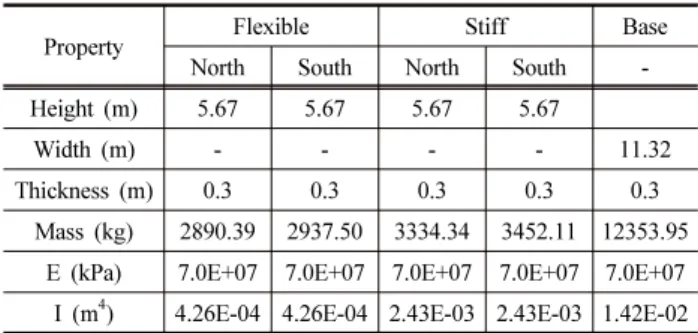
Table 1. Prototype properties of retaining structure considered in numerical simulation (Al Atik & Sitar, 2010)
Property Flexible Stiff Base
North South North South -
Height (m) 5.67 5.67 5.67 5.67
Width (m) - - - - 11.32
Thickness (m) 0.3 0.3 0.3 0.3 0.3
Mass (kg) 2890.39 2937.50 3334.34 3452.11 12353.95 E (kPa) 7.0E+07 7.0E+07 7.0E+07 7.0E+07 7.0E+07 I (m
4) 4.26E-04 4.26E-04 2.43E-03 2.43E-03 1.42E-02
3. Numerical Simulation
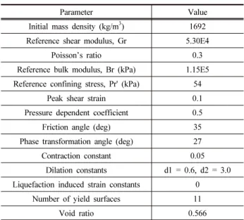
Centrifuge tests described in previous section was numerically simulated using pressure-dependent, multi yield surface, plasticity based soil model (PDMY) implemented in OpenSees by Yang et al. (2008). The numerical analysis was performed in prototype scale with 2D assuming plane strain. Prototype properties of retaining structures are presented in Table 1. PDMY02 calibration parameters are presented in Table 2.
Soil was represented by 2D mesh of two degree of freedoms (DOFs) nodes that form quad element. SSPquad
elements (McGann et al., 2012) were used to model soil.
Both stiff and flexible U-shaped cantilever structures are
modeled using beam-column element with each node of
Table 2. PDMY02 modeling parameters considered in numerical simulation (Al Atik & Sitar, 2010)
Parameter Value
Initial mass density (kg/m
3) 1692 Reference shear modulus, Gr 5.30E4
Poisson’s ratio 0.3
Reference bulk modulus, Br (kPa) 1.15E5 Reference confining stress, Pr' (kPa) 54
Peak shear strain 0.1
Pressure dependent coefficient 0.5
Friction angle (deg) 35
Phase transformation angle (deg) 27
Contraction constant 0.05
Dilation constants d1 = 0.6, d2 = 3.0 Liquefaction induced strain constants 0
Number of yield surfaces 11
Void ratio 0.566
Fig. 2. Two-dimensional plane strain computation model domain
Fig. 3. Soil-wall interface configuration
3DOFs. A linear elastic material was adopted to simulate response of U-shaped retaining structures. Fig. 2 shows the computational model, newly developed graphical user interface for OpenSees (Papanikolaou et al., 2017) is used for mesh generation. Soil structure interaction between wall and soil was modeled using zero-length springs implemented in OpenSees. Horizontal and vertical springs were used to connect backfill soil with wall and base slab with base soil respectively. Soil structure interaction configuration is shown in Fig. 3. Stiffness for springs is in normal
direction is calculated using
min