Crack Propagation at Boundary Face of Composite Compact Tension Specimen
Jae-Ung Cho
1and Moon-Sik Han
2,#1 Department of Mechanical Engineering, Kongju National University, 275, Budae-dong, Seobuk-gu, Cheonan-si, Chungnam, Republic of Korea, 331-717 2 Department of Mechanical and Automotive Engineering, Keimyung University, 2800 Dalgubeoldaero, Dalseo-Gu, Daegu, Republic of Korea, 704-701
# Corresponding Author / E-mail: [email protected], TEL: +82-53-580-5255 (Manuscript received: Nov, 2, 2012 / Revised: Feb, 4, 2013 / Accepted: Feb, 5, 2013)
In this study, fatigue crack propagation in composite material under fatigue is investigated by simulation result.
When another material on the specimen exists vertically to the crack line, the phenomena that crack may go straight or propagate along the boundary face according to the elastic modulus ratio of another material to matrix are investigated with compact tension specimen by compliance method. Crack propagation direction is evaluated by compliance method. By arranging this study result systematically about the crack propagation behavior due to the stiffness of inhomogeneous material, high-tech material (automobile, aircraft and steel industry) can be improved.
The estimation of safety design and life (construction & nuclear power station, etc.) will be of great value industrially.
KEYWORDS: Fatigue crack propagation, Composite, Compact tension specimen, Matrix, Inhomogeneous material, Elastic modulus, Compliance method
1. Introduction
The study investigates the behaviour of a main crack, propagating toward boundary face by simulation. The simulation results show that debonded boundary face changes the crack growth path during some phase of a crack tip passage toward boundary face. A material stiffness ratio between matrix and another material also tends to change crack growth path. As the presence of inhomogeneities was shown to influence the crack growth considerably, inhomogeneity in engineering material is known to influence the strength properties significantly. This study aims towards numerical simulation on the behavior of fatigue defect travelling toward inhomogeneous material
(1~10). The simulation geometry of composite compact tension
specimen (C. T.) is investigated(11~12). The objective of this study is to examine the effect of the fatigue properties due to the inhomogeneous materials and the stiffness ratio between matrix and another material by using analytical results. By arranging this study result system- atically about the crack propagation behavior due to the stiffness of inhomogeneous material, high-tech material (automobile, aircraft and steel industry) can be improved. The estimation of safety design and life (construction & nuclear power station, etc.) will be of great value industrially.
2. Study Result
2.1 Model of compact tension(C-T) specimen
As the model at this study, C-T specimen is selected as shown by Fig. 1. In this analysis, the matrix is brass and the right side at the boundary face is mild steel or tungsten carbide as another material.
The matrix and another material is bonded at this boundary. The materials of specimen models are homogeneous brass(brass+brass), brass+mild steel and brass+tungsten carbide. The material properties are shown by Table 1. As this model becomes symmetrical up and down, the constraint condition is shown by Fig. 2 The analytical condition is plane strain and load(P) is applied with 490 N. Fig. 3 shows finite element model for compact tension specimen. The number of elements and nodes are 1599 and 854 respectively.
Stress intensity factor is obtained by total energy method as the case of a single material. By the formula at ASTM E-399(13), stress intensity factor about C-T specimen with only matrix is as follows;
(Useful range: ≤
≤ ) (1)
As the error between calculatedK1value andK1value by formula (1) as ASTM E-399 becomes below 0.3% as shown by Table 2, there ICMTE
Fig. 1 Simulation model for composite compact tension specimen
Table 1 Material property
Material Elastic modulus(GPa) Poisson’s ratio
Brass 100.6 0.35
Mild steel 205.8 0.31
Tungsten carbide 534.4 0.22
Fig. 2 Constraint condition for simulation model
Fig. 3 Finite element model for numerical analysis (compact tension specimen)
Table 2 Calculated K1value by Total Energy method compact tension specimen
a Calculated
K1value
K1value by
ASTM E-399 Error(%)
23.5 1.92881 1.93068 -0.0972
24.5 2.04465 2.04398 0.0330
25.5 2.17235 2.16958 0.1279
26.5 2.31489 2.31003 0.2103
27.5 2.47436 2.46843 0.2403
28.5 2.65274 2.64840 0.1636
(Units : a = mm, K1 = MPa・m1/2)
Fig. 4 Comparison of compliance VS. crack length for brass, brass+
steel compact tension specimens
is no objection at comparison analyses about inhomogeneous composites.
2.2 Simulation analysis result
As crack propagates as the length(a) of 23.5 to 29.5 mm as shown by Fig. 4, the value of compliance changes. The crack propagates slowly in case of homogeneous brass(brass+brass). But the crack propagates more slowly than homogeneous brass (brass+brass) in case of inhomogeneous brass+ mild steel.
This phenomenon is due to the influence of stiff steel with the elastic modulus larger 2 times than the mild brass matrix. By the result of fatigue test, crack propagates with another direction instead of progressing vertically on boundary face when crack propagates from matrix material to another material.
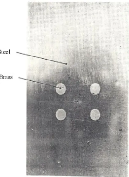
Photo 1 and 2 show the specimens before and after fatigue fracture in case of center cracked specimen with another material. During fatigue process, main crack propagates and stops. And the small crack initiated from holes is propagated due to final fracture(14).
Photo 1. Specimen before fatigue fracture in case of center cracked specimen with another material
Photo 2. Specimen after fatigue fracture in case of center cracked specimen with another material
Photo 3. Specimen before fatigue fracture in case of compact tension specimen bonded with another material
Photo 4. Specimen after fatigue fracture in case of compact tension specimen bonded with another material
Fig. 5 Change of compliance per unit of crack growth (a) Only the main crack is growing. (b) Only the secondary cracks are growing
Photo 3 and 4 show the specimens before fatigue fracture in case of compact tension specimen bonded with another material(14).
In case of Photos 1 and 2, a crack advance of 1 mm (one element length) is assumed on the calculation. The situation shown in Fig. 5 is simulated: here the main crack is stationary and the secondary crack is advanced. In this case the compliance change per unit of crack growth is 2.61 × 10⁻⁷ N -1, but because there are two particles and the FEM calculations assume symmetry, this is equivalent to a compliance change per unit of crack growth of about 1.32 × 10⁻⁷ N -1 caused by advance (one secondary crack, only, i.e. about the same change as for advance of the main crack, only. Also here a crack advance of 1mm was assumed. Due to the sensitivity of the compliance change to the crack length one can expect a higher compliance change for the next crack advance.
During fatigue process, main crack propagates. In addition to main crack propagation, the round crack initiated along the hole boundary from the lower left to the upper right near bonded hole from holes is propagated due to final fracture. To examine the phenomenon, the
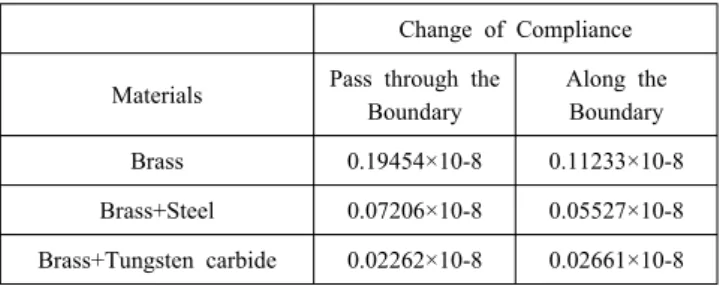
Table 3 Comparison about the Changes of Compliance ∆λ(C. T.
Specimens with inhomogeneous composites)
Change of Compliance
Materials Pass through the Boundary
Along the Boundary
Brass 0.19454×10⁻⁸ 0.11233×10⁻⁸
Brass+Steel 0.07206×10⁻⁸ 0.05527×10⁻⁸ Brass+Tungsten carbide 0.02262×10⁻⁸ 0.02661×10⁻⁸ (Unit : m/N)
value of compliance change is calculated in case that main crack near boundary face propagates along the face. Table 3 shows comparison about the changes of compliance at C. T. specimens with homogeneous and inhomogeneous composites. When crack on matrix propagates horizontally on boundary face in case of homogeneous (brass+brass) specimen, the compliance change becomes 17.7 times as much as the case that crack propagates vertically. When crack propagates and pass through boundary face in case that steel with the elastic modulus of two times as large as brass is bonded with brass matrix, the value of compliance change becomes 1.3 times as much as the case that crack is bent along the boundary face. When crack propagates and pass through boundary face in case that tungsten carbide with the elastic modulus of five times as large as brass is bonded with brass matrix, the value of compliance change becomes 0.85 times as much as the case that crack is bent along the boundary face. When there is harder material in front of main crack, the compliance change becomes smaller by comparing the case that there is only matrix and the crack propagates more slowly. As another material in front of main crack becomes harder, crack propagates more slowly. In case that the elastic modulus of another material becomes 5 times as much as matrix, main crack does not pass through the another material. After the crack is bent, it propagates along the boundary face. When another material on the specimen exists vertically to the defect line, the phenomena that defect may go straight or propagate along the boundary face according to the elastic modulus ratio of another material to matrix are investigated by compliance method. The propagation of main crack changes according to the ratio of elastic modulus under the condition of the existence of another material perpendicular on the front of main crack.
3. Conclusion
In this study, fatigue defect propagation in composite material under fatigue is investigated by simulation result.
(1) When another material on the specimen exists vertically to the defect line, the phenomena that defect may go straight or propagate along the boundary face according to the elastic
modulus ratio of another material to matrix are investigated by compliance method.
(2) Crack propagation direction is evaluated by compliance method.
By arranging this study result systematically about the crack propagation behavior due to the stiffness of inhomogeneous material, high-tech material (automobile, aircraft and steel industry) can be improved.
(3) The estimation of safety design and life (construction & nuclear power station, etc.) will be of great value industrially.
ACKNOWLEDGEMENT
This research was supported by Basic Science Research Program through the National Research Foundation of Korea (NRF) funded by the Ministry of Education, Science and Technology (2011-0006548).
REFERENCES
1. Cho, J. U., Xie, L., Cho, C. and Lee, S. K., 2012, “Crack propagation of CCT foam specimen under low strain rate fatigue,” Int. J. Fatigue, Vol. 35, pp. 23~30.
2. Norman, E.D., 1999, “Engineering method for deformation, fracture, and fatigue,” Mech. Behav. Mater., Vol. 2, pp. 357~ 558.
3. Sugimura, Y., Meyer, J, He, M.Y., Bart-Smith, H., Grenestedt, J.
and Evans, A.G., 1997, “On the mechanical performance of closed cell Al alloy foams,” Acta Mater., Vol. 45, pp. 5245~5259.
4. Grenestedt, J. L., 1998, “Influence of wavy imperfections in cell walls on elastic stiffness of cellular solids,” J. Mech. Phys. Solids, Vol. 46, pp. 29~50.
5. Anderson, T. L., 1995, Fracture Mechanics: Fundamentals and applications, CRC Press, USA.
6. Bannantine, J. A. and Come,r J. J., Handrock, J., 1989, Fundamentals of metal fatigue analysis, Prentice Hall, USA.
7. Kwak, D. S., Kim, S. H. and Oh, T. Y., 2006, “Effect of a single applied overload on fatigue crack growth behavior in laser-welded sheet metal,” Int. J. Precis. Eng. Manuf., Vol. 7, No.
3, pp. 30~34.
8. Liu, J., Wang, Y. and Li, W., 2010, “Simplified fatigue durability assessment for rear suspension structure,” Int. J. Auto. Tech., Vol.
11, No. 5, pp. 659~664.
9. Yongming, L. and Sankaran, M., 2009, “Fatigue Limit Prediction of notched Components using Short Crack Growth Theory and an Asymptotic Interpolation Method,” Engineering Fracture Mechanics, Vol. 76, No. 15, pp. 2317~2331.
10. Paul, A., Seshacharyulu, T. and Ramamurty, U., 1999, “Tensile strength of a closed-cell Al foam in the presence of notches and holes,” Scripta Mater., Vol. 40, No. 7, pp. 809~814.
11. Choi, B. K. and Jang, K. C., 2005, “Fatigue Characteristics and FEM Analysis of 18%Ni(200) Maraging Steel,” Trans. of
Korean Soc. of Mach. Tool Eng., Vol.14, No.2, pp. 75~82.
12. Kim, K. S., Jung, H. C., Kim, K. S., Park, C. J. and Jang, H. S., 2010, “A Study on a Relationship Between the Surface Roughness of Fracture CT Specimen Broken By Fatigue Crack Growth and the Moments,” Trans. of Korean Soc. of Mach. Tool Eng., Vol. 19, No. 4, pp. 462~468.
13. Srawley, J. E., 1976, “Wide Range stress intensity Factor expressions for ASTM E-399 Standard Fracture toughness specimens,” Int. J. Fract., Vol. 12, pp. 475~476.
14. Cho, J. U., Lee, O. S., and Kim, S. C., 1992, “Fatigue crack propagation between holes and particles,” Int. J. Fract., Vol. 56, pp. 299~316.