• 검색 결과가 없습니다.

Radiation Shielding Property of Concrete Using the Rapidly Cooled Steel Slag from Oxidizing Process in the Converter Furnace as Fine Aggregate

N/A
N/A
Protected

Academic year: 2021

Share "Radiation Shielding Property of Concrete Using the Rapidly Cooled Steel Slag from Oxidizing Process in the Converter Furnace as Fine Aggregate"

Copied!
12
0
0

로드 중.... (전체 텍스트 보기)

전체 글

(1)

pISSN 1598-2033 eISSN 2233-5706

Journal of the Korea Institute of Building Construction, Vol. 12, No. 5

http://dx.doi.org/10.5345/JKIBC.2012.12.5.478 www.jkibc.org

Radiation Shielding Property of Concrete Using the Rapidly Cooled Steel Slag from Oxidizing Process in the Converter Furnace as Fine Aggregate

Kim, Jin-Man

1

Cho, Sung-Hyun

2

Kwak, Eun-Gu

3*1)

Department of Architectural Engineering, Kongju National University, Cheon-an, ChungNam, 330-717, Korea

1

Hanil Cement technical center, DaeJeon, 306020, Korea

2

Environment-Friendly Concrete center, Kongju National University, Cheon-an, ChungNam, 330-717, Korea

3

Abstract

Each year, about four million tons of steel slag, a by-product produced during the manufacture of steel by refining pig iron in the converter furnace, is generated. It is difficult to recycle this steel slag as aggregate for concrete because the reaction with water and free-CaO in steel slag results in a volume expansion that leads to cracking. However, the steel slag used in this study is atomized using an air-jet method, which rapidly changes the melting substance at high temperature into a solid at a room temperature and prevents free-CaO from being generated in steel slag. This rapidly-cooled steel slag has a spherical shape and is even heavier than natural aggregate, making it suitable for the aggregate of radiation shielding concrete. This study deals with the radiation shielding property of concrete that uses the rapidly-cooled steel slag from the oxidizing process in the converter furnace as fine aggregate. It was shown that the radiation shielding performance of concrete mixed with rapidly-cooled steel slag is even more superior than that of ordinary concrete.

Keywords : rapid-cooled steel slag, radiation shielding concrete, analysis of radiation shielding

1. Introduction

The construction plan for the Shin-wooljin nuclear power plant and a number of contracts of nuclear power plant construction planned have recently been in issue. In general, of the radiation shielding technologies for structures, heavy weight concrete that contains metal aggregate, including magnetite and hematite with high content of iron(Fe), and that makes the concrete heavier in weight is typically used, or the walls are built thicker with OPC. However, it is difficult to

Received : November 30, 2011 Revision received : June 27, 2012 Accepted : July 15, 2012

* Corresponding author : Kwak, Eun-gu

[Tel: 82-41-566-8651, E-mail: [email protected]]

ⓒ2012 The Korea Institute of Building Construction, All rights reserved.

smoothly supply the metal aggregate such as magnetite or hematite, bringing about an increase in construction cost, and it presents a high risk of cracks on concrete caused by heat of hydration due to the increased wall thickness[1,2]

Korea is the world’s 5

th

largest producer of iron, and the production quantity is increasing annually, which means that the quantity of by-products is also increasing. By-products made in the process of iron production can be broadly classified into blast furnace slag and steel slag.

Blast furnace slag is widely used as raw material

for cement, concrete aggregate and recycled

aggregate for road, while steel slag cannot be

widely used because of its volume expansion and

subsequent collapse by free lime(CaO), which

means that there are limitations in terms of its

use as construction material[3,4,5].

(2)

Recently a technique for manufacturing stable aggregate for concrete was developed that uses rapid cooling of the fused steel slag to prevent free CaO from being generated. Studies have been actively conducted to find more appropriate usages of the aggregate[6,7]. When the slag is rapidly cooled, the content of free CaO that could cause a volume expansion and subsequent collapse is 0.15%, and the rapidly cooled steel slag was reported to be stable in the situation of volume expansion and collapse[8]. The particle shape of rapidly cooled steel slag aggregate has high roundness or sphericity, which leads to high solid volume and unit volume weight. The steel slag is characterized to have high density due to there being about 40% of iron(FeO) in chemical property. Studies have been actively performed on the physical characteristics of rapidly cooled steel slag aggregate to use the aggregate for high density concrete and for polymer concrete with the utilization of high solid volume.

However, there have been few studies done on the characteristics of its high density. It is believed the rapidly cooled steel slag can be used in place of the existing metal aggregate such as magnetite or hematite with high density[9].

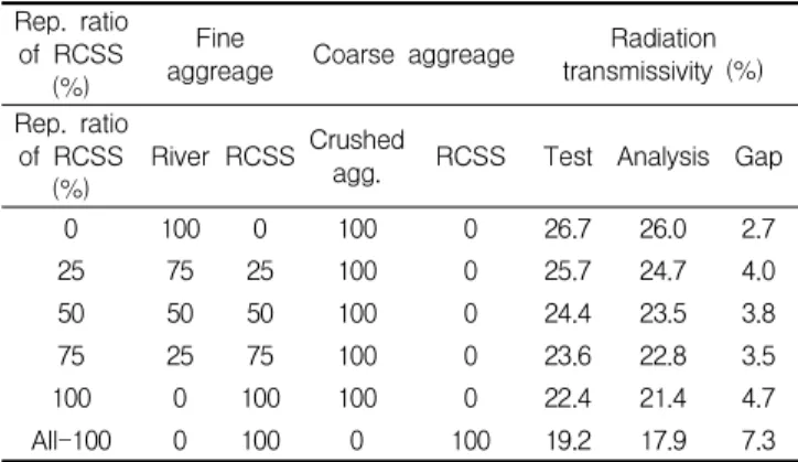
Accordingly, the radiation shielding characteristics of the concrete with rapidly cooled steel slag were tested to determine whether or not the rapidly cooled steel slag could be utilized as aggregate for radiation shielding concrete. To do this, the replacement ratio of the rapidly cooled steel slag was set differently to manufacture the radiation shielding concrete specimen. Specimens were then tested to determine their radiation shielding ability.

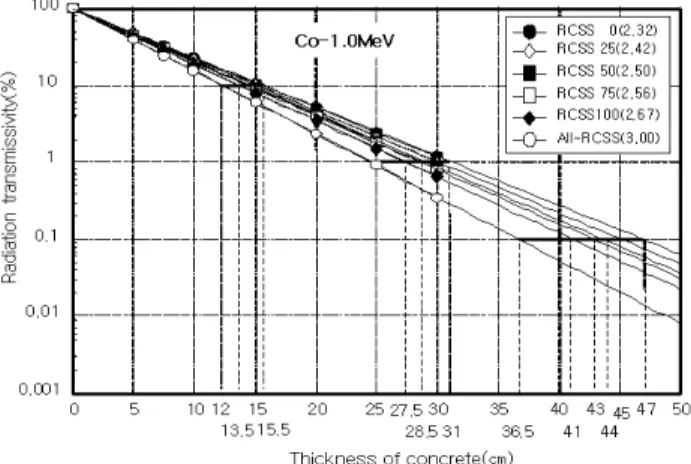
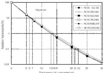
Radiation shielding by thickness was evaluated using the Monte Carlo method based on the measurement result of radiation shielding to conduct a quantitative analysis of the reduction in thickness of a shielding body when using the

rapidly-cooled steel slag instead of natural aggregate.

1.2 Research method and scope

This study aims to determine the possibility of using, as aggregate for radiation shielding concrete, the steel slag generated by rapidly cooling the converter slag obtained in the process of iron production using an air-jet method. For the experiment and analysis, the previous studies related to radiation shielding analysis and the shielding analysis using source term were reviewed. Based on the review, concrete specimens were manufactured using the rapidly-cooled steel slag as aggregate. A gamma ray spectrometer was used to analyze the radiation shielding ability.

2. Literature review

2.1 Principles of shielding analysis

The basic principle of radiation shielding analysis is to obtain the solution of the transport equation.

Known as the Boltzmann transport equation, the transport equation can be largely divided into two approaches.

One is the deterministic approach, which expresses the radiation field using the equation that shows energy and transport direction, and distribution of number density at a given point. Distribution of number density was determined by a mathematical transport equation.

The other is the probability approach, a simulation of particle trajectory according to reaction probability, using probability distribution function. The probability approach is called the Monte Carlo method, which is a class of computational algorithms that can calculate the average value of repeated random behaviors of particles as a deterministic value.

The Monte Carlo method has been used widely

(3)

not only because the cross-section of continuous has recently been used to resolve the fundamental problem with the solution, but also because it provides an accurate 3D simulation of the transport process in the given structure. The Monte Carlo method takes considerable time to simulate the actual behaviors of particles as they are. With the rapid advancement of computing technologies in recent years, the problems caused by computer performance have been gradually resolved. Therefore, the system given in terms of radiation shielding analysis is considerably complex, and it is better to employ the Monte Carlo method that performs a statistical analysis compared with numerical approximation. The Monte Carlo method is based on statistic characteristics, and its drawback is that a numerically analyzed solution cannot be obtained.

In addition, there is some statistical uncertainty in the result obtained though the Monte Carlo method. In other words, the deterministic approach gives an accurate true value of quantity through simplification and approximation of a given problem, while the Monte Carlo method gives all the approximate solutions through an accurate simulation of a given problem[10].

There are diverse Monte Carlo radiation transport codes, including MCNP, MORSE, EGS, and ETRAN. Of these, MCNP code has a long history, having been developed since the 1970s with massive investments of manpower and time, including more than 500 researchers. The MCNP is the most widely used Monte Carlo radiation transport code in the world. The reliability of MCNP was proven for its use in diverse radiation-related fields.

The MCNP code was first introduced in 1983, and MCNP3 was distributed throughout the world.

Since then it has been improved to have electrical

transport function in MCNP4A(1990), and continued to be developed into MCNP4B(1997) and MCNP4C(2000). In addition, the recent release of MCNPX 2.4 has improved to expand the radiation energy range up to 150 MeV from the previous model MCNP4C. It is designed to transport a total of 34 particles including proton, helium nucleus, and other elementary particles. The radiation analysis was extended to apply to the following fields:

·Research of radioactive isotope production using an particle accelerator, including transmutation of radioactive waste

·Studies of cosmic-ray radiation shielding for high-altitude airliners and space shuttles

·Neutron and proton therapy

·Accelerator-based imaging using neutron and proton

·Neutrino experiment

·Radiation protection and shielding

·Radiation shielding design for particle accelerator

·Safety analysis of nuclear criticality, etc.

2.2 Radiation shielding analysis by source item The radiation shielding analysis is divided into three or four steps. First, the source term is analyzed. Second, the distribution and intensity of radiation, which is the most fundamental element in the radiation shielding, is evaluated at a point after radiation was put.

The most basic question in the design and analysis of radiation shielding is whether or not the wall is sufficiently thick to protect people or living creatures from gamma rays or neutrons.

These two rays penetrate more than other types of

radioactive rays, and it is difficult to lessen their

intensity. In a nuclear power plant, a variety of

gamma rays are generally emitted. Gamma rays

(4)

W/C (%)

ratio of RCSS*

(%)

Target slump (㎝)

Agg. Fine ration

(%) water Unit (kg/㎥)

Unit volume (l/㎥) Unit weight (kg/㎥)

Test items Cemen

t

Fine agg. Coarse agg.

Cemen t

Fine agg. Coarse agg.

RCSS River sand RCSS Crush

agg. RCSS River sand RCSS Crushed agg.

35 0

18±2.5 46 175

159 288 0 0 338 500 743 0 0 872

· Radiation shielding

· Atom and density

25 159 216 72 0 338 500 557 257 0 872

50 159 144 144 0 338 500 371 514 0 872

75 159 72 216 0 338 500 186 771 0 872

100 159 0 288 0 338 500 0 1028 0 875

All-100** 159 0 288 338 0 500 0 1028 1166 0

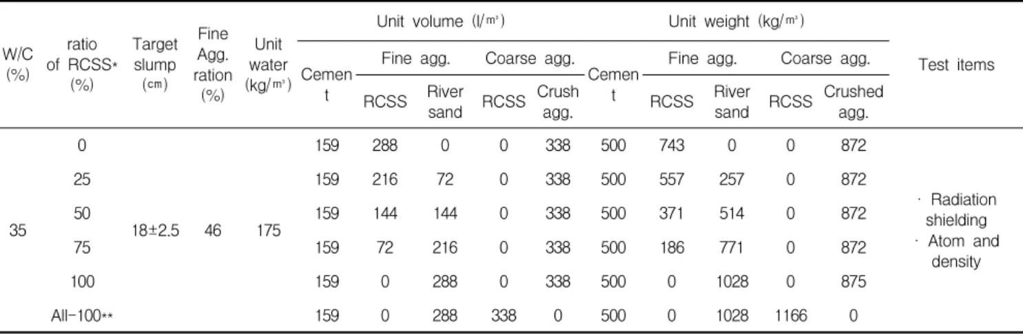
* RCSS : rapid-cooled steel slag

** All-100 : All aggregate uses rapid-cooled steel slag.

Table 1. Mix plan

strong enough to penetrate the shielding body of the nuclear reactor are radiation generated through reaction with neutrons around the pressure vessel.

o Fission gamma rays

o Fission-product-decay gamma ray o Capture gamma ray

o Inelastic-scattering gamma ray o Reaction-product gamma ray o Activation-product gamma ray o Annihilation radiation

o Bremsstrahlung

In addition, the neutrons generated in the process of operating a nuclear power plant are created in the course of nuclear decay itself.

o Fission neutrons o Activation neutrons o Photo-neutrons

o Particle-reaction neutrons

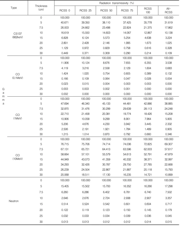
To apply the shielding analysis and result, the energy of gamma ray equivalent to total energy was selected, and the neutron was classified into thermal neutron and fast neutron to analyze radiation shielding by dividing into sections depending on energy level.

3. Experiment plan

3.1 Concrete mixture of specimens for shielding performance test

Table 1 indicates the concrete mixture for specimen manufacture and radiation shielding analysis. The concrete specimen was mixed to have a water to cement ratio of 35%, unit volume of cement of 500kg/m

3

, and fine aggregate ratio of 46%.

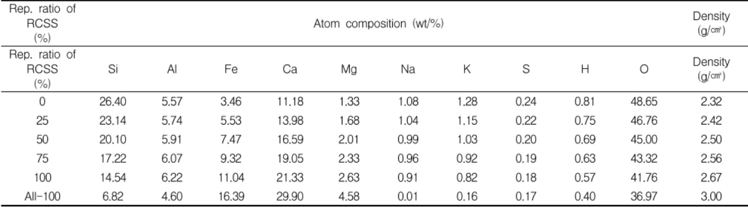
The replacement ratio of rapidly-cooled steel slag was set as 0%, 25%, 50%, 75%, and 100% against river sand. In addition, a mixture with rapidly-cooled steel slag in place of fine and coarse aggregate was considered.

3.2 Materials

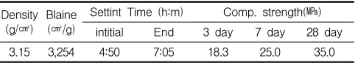
Ordinary Portland cement with a density of 3.15 g/㎤ was used. The physical properties of OPC are indicated in Table 2. River sand and rapidly-cooled steel slag were used as fine aggregate, and 19 mm crushed gravel and rapidly-cooled steel slag was used as coarse aggregate. The physical properties of aggregate are indicated in Table 3.

Polycarbonate super-plasticizer (brown liquid,

specific gravity 1) was used.

(5)

Table 2. The physical properties of cement Density

(g/㎤) Blaine (㎤/g)

Settint Time (h:m) Comp. strength(㎫) intitial End 3 day 7 day 28 day

3.15 3,254 4:50 7:05 18.3 25.0 35.0

Table 3. The physical properties of aggregate

Type Max

(mm) size Density

(g/㎤) Absor

ption

(%) F.M. Unit weight (kg/m3) Solid ratio (%) Fine agg.

RCSS 5 3.57 0.42 3.10 2.263 63.75

River 5 2.58 1.19 3.30 1.575 63.40

Coarse agg.

RCSS 19 3.48 0.90 7.41 1,908 55.23

Crush 19 2.58 0.99 6.96 1,507 58.93

3.3 Test specimen for radiation shielding

7.5cm

10cm

10cm

Gamma rays

7.5cm

10cm

10cm

Gamma rays

Figure 1. Size of Test specimen

As shown in Figure 1, the test specimen for radiation shielding was made to 7.5cm×10cm×

10cm in size and wet cured for 28 days at 20±

3℃. The radiation shielding was measured at 28 days of curing after the unit volume weight was measured using a test system for gamma ray illustrated in Figure 1. Cs 137-662keV gamma ray was used for the test.

Figure 2. Test system of gamma

3.4 A model for shielding calculation

MCNPX 2.4 was used, which was designed to set the radiation transportable energy range at up to 150MeV applicable to the high-energy particle accelerator. In addition, the radioactive source was designed to be incident at the point 1m away from the infinite slab, and the detector used in the test was made to be a volume of 30cm sphere identical to the size of the measure.

In the test radiation beam was measured at 5, 10, 15, 20, 25 and 30cm of shielding body, respectively not to mention 7.5cm of wall thickness basically included in the test. The photon beam of 0.1, 1 and 10 MeV and gamma ray of 662keV(Cs 137) were selected for the source term to verify the test, and the pressurized water reactor (PWR) spectrum presented in the IAEA Technical Report 403 was used for the neutron source.

As the source term has the greatest impact on

the shielding calculation, the accuracy of the

description of the source term is an important

factor that determines the reliability of code

calculation. However, the object to be protected

was not specifically selected in this study, and

production evaluation of the neutron source term

was done by computation for the protection to be

employed for general use. IAEA Technical Report

403 “Compendium of neutron spectra and detector

responses for radiation protection purposes” was

referred to for the neutron source. The spectrum

actually measured at the test room outside the

reactor-pressured vessel now operated in the

Czech Republic was entered directly on MCNPX to

perform the computation[8]. IAEA Technical Report

403 presents in the tables and graphs typical

neutron spectrums actually measured or computed

at diverse facilities where neutron is detected, and

it is expected that the technical report will be

widely utilized when performing the shielding

(6)

Rep. ratio of

RCSS (%) Atom composition (wt/%) Density

(g/㎤) Rep. ratio of

RCSS (%) Si Al Fe Ca Mg Na K S H O Density

(g/㎤)

0 26.40 5.57 3.46 11.18 1.33 1.08 1.28 0.24 0.81 48.65 2.32

25 23.14 5.74 5.53 13.98 1.68 1.04 1.15 0.22 0.75 46.76 2.42

50 20.10 5.91 7.47 16.59 2.01 0.99 1.03 0.20 0.69 45.00 2.50

75 17.22 6.07 9.32 19.05 2.33 0.96 0.92 0.19 0.63 43.32 2.56

100 14.54 6.22 11.04 21.33 2.63 0.91 0.82 0.18 0.57 41.76 2.67

All-100 6.82 4.60 16.39 29.90 4.58 0.01 0.16 0.17 0.40 36.97 3.00

Table 4. Atom analysis according concrete mix ratio

calculation for neutron flux, particularly in the fields in which information of the neutron source term is insufficient or unavailable. It provides a wide range of detailed neutron spectrums including typical PWR, BWR, particle accelerator for medical treatment, high-energy particle accelerator, cosmic-ray, nuclear fuel cycle facilities, various neutron sources, and Boron neutron capture therapy. The gamma energy used in this shielding analysis is the nuclide generally emitted from the nuclear power plant, which basically includes Cs 137 gamma ray that can be analyzed and evaluated in a laboratory. The shielding performance was evaluated according to energy level, and Co was selected as the gamma source that can be represented as a general photon beam because of its applicability from low-energy photon(0.1MeV) to high-energy photon(10MeV). In addition, it can be applied not only to a nuclear power plant but also to a general company.

3.5 Geometric model and does conversion method The ultimate purpose of radiation shielding is to minimize radiation exposure of a human body. For this reason, to evaluate the shielding body containing the rapidly-cooled steel slag, a radiation shielding transport model was selected, and could be applicable to any of the shielding

designs by assuming an infinite slab, which provides protection from a point source and the entire source. Infinite slab was assumed to minimize the uncertainty, since a geometric model is usually complex due to the high uncertainty caused by modeling. To concentrate the analysis on the shielding performance of the body, the parameters for the geometric model were used at the minimum.

In addition, by expressing the shielding performance in a percentile of radiation beam, the source can be applied regardless of beam and dose rate. Thus, when the effective beam was evaluated using ICRP74 or another method, it can be converted into dose rate by applying the shielding ratio.

3.6 Verification of the evaluation method

To verify the results of the analysis of shielding

performance, the measurement values were

obtained by measuring radiation transmissivity

using a gamma spectrometer. In the test, the

shielding concrete specimen made to the size of

7.5cm×10cm×10cm and the test source of Cs

137-662kev was used. The shielding concrete used

to make the specimen was analyzed in terms of

element and density, and the analysis results are

indicated in Table 4. Analysis values were obtained

(7)

through an analysis using the MCNPX 2.4 code by assuming that the specimen was 7.5cm thick and had an identical composition of elements and density to those shown in Table 4, and the source term of Cs 137-622kev was used. The validity was verified by comparing the measurement values with the analysis values.

4. Analysis results and consideration

4.1 Verification of the shielding analysis

Table 5 indicates the measurement values and the analysis values obtained through the aforementioned process. The values were determined through analysis to have been matched within up to 7.3%. The difference is believed to be reasonable considering that the concrete specimen was heterogeneous and that a simple structure that could be generally used was considered, rather than reflecting the identical geometric structure to that in the measuring condition in consideration of the general use of the analysis values.

Rep. ratio of RCSS

(%)

aggreage Fine Coarse aggreage Radiation transmissivity (%) Rep. ratio

of RCSS

(%) River RCSS Crushed agg. RCSS Test Analysis Gap

0 100 0 100 0 26.7 26.0 2.7

25 75 25 100 0 25.7 24.7 4.0

50 50 50 100 0 24.4 23.5 3.8

75 25 75 100 0 23.6 22.8 3.5

100 0 100 100 0 22.4 21.4 4.7

All-100 0 100 0 100 19.2 17.9 7.3

* Test date is used specimen thickness 75㎜

Analysis date is a date of simulation

Table 5. Test and analysis according replacement ratio RCSS

Through this verification, it was proven that the source term and the geometric structure for computation was performed appropriately. The computation process was applied to all the energies

to be analyzed in this study and the computation was performed.

4.2 Evaluation and review of radiation shielding

4.2.1 Gamma ray of Cs137 - 662 keV

Table 6 indicates the analysis results by radiation transmissivity and shielding thickness according to the replacement ratio of the rapidly-cooled steel slag. Figure 3 illustrates the analysis results of Cs137-662KeV by replacement ratio and radiation transmissibility in a semi log plot.

Figure 3 . Correlation on the gamma transmissivity according to specimen thickness(662keV)

It was shown that the higher the replacement

rate of rapidly-cooled steel slag as fine aggregate,

the lower the gamma transmissivity. The intensity

of Cs 137-622keV gamma ray was reduced by 1/10,

the thickness of 12.7cm was needed when using

river sand as aggregate while the thickness of

11.2cm was needed when the aggregate was

replaced 100% with the rapidly-cooled steel slag,

from which it was proven to reduce by about 1.5cm

in thickness. In addition, when using fine and

coarse aggregates together with rapidly-cooled steel

slag, the thickness of 10cm was needed, which was

proven to reduce by about 2.7cm in thickness

compared with the wall using river sand and

(8)

Type Thickness (cm)

Radiation transmissivity (%)

RCSS 0 RCSS 25 RCSS 50 RCSS 75 RCSS

100 All-

RCSS

G a m m a

CS137 (662keV)

0 100.000 100.000 100.000 100.000 100.000 100.000

5 40.671 39.350 38.110 37.425 35.778 31.619

7.5 26.003 24.662 23.498 22.824 21.375 17.862

10 16.619 15.550 14.603 14.067 12.867 10.138

15 6.828 6.124 5.573 5.254 4.638 3.224

20 2.801 2.428 2.146 1.995 1.673 1.025

25 1.129 0.972 0.829 0.758 0.616 0.328

30 0.449 0.371 0.309 0.290 0.214 0.109

(0.1MeV) CO

0 100.000 100.000 100.000 100.000 100.000 100.000

5 11.906 10.124 8.676 7.655 6.355 3.538

7.5 4.119 3.216 2.558 2.129 1.604 0.683

10 1.424 1.020 0.754 0.605 0.389 0.132

15 0.166 0.109 0.064 0.047 0.028 0.004

20 0.023 0.015 0.004 0.003 0.003 0.000

25 0.003 0.003 0.002 0.001 0.000 0.000

30 0.002 0.000 0.000 0.000 0.000 0.000

(1MeV) CO

0 100.000 100.000 100.000 100.000 100.000 100.000

5 47.694 46.340 45.133 44.481 42.886 38.885

7.5 32.870 31.476 30.299 29.639 28.113 24.248

10 22.710 21.458 20.381 19.774 18.426 15.208

15 10.906 10.058 9.299 8.901 7.964 5.905

20 5.206 4.676 4.230 3.942 3.445 2.332

25 2.506 2.191 1.921 1.784 1.489 0.905

30 1.215 1.014 0.870 0.792 0.660 0.346

(10MeV) CO

0 100.000 100.000 100.000 100.000 100.000 100.000

5 76.715 75.706 74.714 74.036 72.825 69.307

7.5 67.131 65.721 64.413 63.596 62.003 57.617

10 58.664 57.101 55.579 54.613 52.791 47.879

15 44.949 43.073 41.359 40.332 38.371 32.997

20 34.293 32.426 30.787 29.750 27.785 22.668

25 26.239 24.504 22.867 21.887 20.118 15.793

30 20.068 18.511 17.130 16.235 14.721 10.899

Neutron

0 100.000 100.000 100.000 100.000 100.000 100.000

5 15.405 15.502 15.700 16.352 16.266 17.298

7.5 6.260 6.286 6.402 6.781 6.740 7.502

10 2.646 2.676 2.724 2.938 2.907 3.357

15 0.514 0.524 0.542 0.601 0.604 0.717

20 0.122 0.119 0.123 0.150 0.145 0.179

25 0.032 0.033 0.034 0.039 0.036 0.045

30 0.013 0.013 0.012 0.012 0.014 0.015

Table 6. Result of radiation Shielding

(9)

crushed gravel as aggregate. When the intensity of the gamma ray was reduced to 1/100, the thickness of 26cm was needed when using river sand as aggregate, while the thickness of 22.5cm was needed when the aggregate was replaced 100% with rapidly-cooled steel slag, which proved that it could be reduced in thickness by about 4.5cm. When using fine and coarse aggregates together with rapidly-cooled steel slag, the thickness of 20cm was needed, which was proven to have a reduction of about 6cm in thickness compared with the wall using river sand and crushed gravel as aggregate.

When the intensity of gamma ray was reduced to 1/1000, the thickness of 38.5cm was needed when using river sand as aggregate, while the thickness of 33.5cm was needed when the aggregate was replaced 100% with rapidly-cooled steel slag, a reduction of about 5cm in thickness. When using fine and coarse aggregates together with rapidly-cooled steel slag, the thickness of 30cm was needed, which was a reduction of about 8.5cm in thickness compared with the wall using river sand and crushed gravel as aggregate.

4.2.2 Gamma ray of Co- 0.1 MeV

Figure 4 illustrates the results of an analysis of Co-0.1 MeV by replacement rate and gamma transmissivity in a semi log plot.

Figure 4. Correlation on the gamma transmissivity according to specimen thickness(0.1MeV)

When the intensity of gamma ray of Co-0.1 MeV was reduced by 1/10, the thickness of 5.5cm was needed when using river sand as aggregate while the thickness of 4cm needed when the aggregate was replaced 100% with the rapidly-cooled steel slag, which was proven to reduce by about 1.5cm in thickness. In addition, when using fine and coarse aggregates together with rapidly-cooled steel slag, the thickness of 3.5cm was needed, which was proven to reduce by about 2cm in thickness compared with the wall using river sand and crushed gravel as aggregate.

When the intensity of gamma ray was reduced to 1/100, the thickness of 11cm was needed when using river sand as aggregate while the thickness of 8.5cm was needed when the aggregate was replaced 100% with the rapidly-cooled steel slag, which was proven to reduce by about 2.5cm in thickness compared with the wall using river sand crushed gravel as aggregate. When using fine and coarse aggregates together with rapidly-cooled steel slag, the thickness of 7cm was needed, which was proven to reduce by about 4cm in thickness compared with the wall using river sand and crushed gravel.

When the intensity of gamma ray was reduced

to 1/1000, the thickness of 16.5cm was needed

when using river sand as aggregate while the

thickness of 13.5cm was needed when the

aggregate was replaced 100% with the

rapidly-cooled steel slag, which was proven to

reduce by about 3cm in thickness compared with

the wall using river sand crushed gravel as

aggregate. When using fine and coarse aggregates

together with rapidly-cooled steel slag, the

thickness of 10.5cm was needed, which was proven

to reduce by about 6.5cm in thickness compared

with the wall using river sand and crushed gravel.

(10)

4.2.3 Gamma ray of Co-1.0Mev

Figure 5 illustrates the results of an analysis of Co-1.0 MeV by replacement rate and gamma transmissivity in a semi log plot.

Figure 5. Correlation on the gamma transmissivity according to specimen thickness(1.0 MeV)

When the intensity of gamma ray of Co-1.0 MeV was reduced by 1/10, the thickness of 15.5cm was needed when using river sand as aggregate while the thickness of 13.5cm needed when the aggregate was replaced 100% with the rapidly-cooled steel slag, which was proven to reduce by about 2cm in thickness. In addition, when using fine and coarse aggregates together with rapidly-cooled steel slag, the thickness of 12cm was needed, which was proven to reduce by about 3.5cm in thickness compared with the wall using river sand and crushed gravel as aggregate.

When the intensity of gamma ray was reduced to 1/100, the thickness of 31cm was needed when using river sand as aggregate while the thickness of 27.5cm was needed when the aggregate was replaced 100% with the rapidly-cooled steel slag, which was proven to reduce by about 3.5cm in thickness compared with the wall using river sand crushed gravel as aggregate. When using fine and coarse aggregates together with rapidly-cooled

steel slag, the thickness of 25cm was needed, which was proven to reduce by about 6cm in thickness compared with the wall using river sand and crushed gravel.

When the intensity of gamma ray was reduced to 1/1000, the thickness of 47cm was needed when using river sand as aggregate while the thickness of 41cm was needed when the aggregate was replaced 100% with the rapidly-cooled steel slag, which was proven to reduce by about 6cm in thickness compared with the wall using river sand crushed gravel as aggregate. When using fine and coarse aggregates together with rapidly-cooled steel slag, the thickness of 36.5cm was needed, which was proven to reduce by about 10.5cm in thickness compared with the wall using river sand and crushed gravel.

4.2.4 Gamma ray of Co - 10 MeV

Figure 6 illustrates the results of an analysis by replacement rate and gamma transmissivity at Co-10 MeV in a semi log plot.

Figure 6. Correlation on the gamma transmissivity according to specimen thickness(10 MeV)

When the intensity of gamma ray of Co-10 MeV

was reduced by 1/10, the thickness of 42cm was

needed when using river sand as aggregate while

(11)

the thickness of 36cm needed when the aggregate was replaced 100% with the rapidly-cooled steel slag, which was proven to reduce by about 6cm in thickness. In addition, when using fine and coarse aggregates together with rapidly-cooled steel slag, the thickness of 31cm was needed, which was proven to reduce by about 9cm in thickness compared with the wall using river sand and crushed gravel as aggregate. When the intensity of gamma ray was reduced to 1/100, the thickness of 88cm was needed when using river sand as aggregate while the thickness of 75cm was needed when the aggregate was replaced 100% with the rapidly-cooled steel slag, which was proven to reduce by about 13cm in thickness compared with the wall using river sand crushed gravel as aggregate. When using fine and coarse aggregates together with rapidly-cooled steel slag, the thickness of 62cm was needed, which was proven to reduce by about 26cm in thickness compared with the wall using river sand and crushed gravel.

When the intensity of gamma ray was reduced to 1/1000, the thickness of 129cm was needed when using river sand as aggregate while the thickness of 108cm was needed when the aggregate was replaced 100% with the rapidly-cooled steel slag, which was proven to reduce by about 21cm in thickness compared with the wall using river sand crushed gravel as aggregate. When using fine and coarse aggregates together with rapidly-cooled steel slag, the thickness of 94cm was needed, which was proven to reduce by about 35cm in thickness compared with the wall using river sand and crushed gravel.

4.2.5 Neutron beam

Figure 7 illustrates the results of an analysis of neutron beam by replacement rate and gamma transmissivity a semi log plot.

Figure 7· Correlation on the gamma transmissivity according to specimen thickness(Neutron)

The gamma transmissity of neutron beam was decreased slightly according to the replacement ratio of rapidly-cooled steel slag, but there were no great differences. When the intensity of neutron beam was reduced by 1/10, about 0.5 cm difference was found in thickness depending on replacement ratio of rapidly-cooled steel slag.

When reduced by 1/100 and 1/1000, differences in thickness of about 1cm and 1.2cm, respectively, were found. The transmissivity of general neutron beam was decreased as the specific gravity increased, but although the aggregate with high specific gravity was used in the test, there were no great differences found.

Through the test analysis, it was found that the higher the density, the lower the intensity of gamma ray, from which it is concluded that the density had an impact on gamma ray. In addition, it is believed that the increase range of density of concrete has a linear relationship with the decrease ratio of intensity of gamma ray.

5. Conclusion

The research findings of shielding concrete

(12)

analysis depending on thickness and replacement ratio of rapidly-cooled steel slag can be summarized as follows:

1) Through the analysis of shielding performance, it was found that for the gamma ray, the higher the replacement ratio of rapidly-cooled steel slag, the better the shielding performance. For the neutron beam, the shielding performance was slightly deteriorated when rapidly-cooled steel slag was used as aggregate.

2) It was found that for the gamma ray, the higher the replacement ratio of rapidly-cooled steel slag, the lower the transmissivity, and when the rapidly-cooled steel slag is used as aggregate, the wall thickness is expected to be decreased. In addition, when fine and coarse aggregates are used with rapidly-cooled steel slag, the wall thickness will be decreased more than when only fine and coarse aggregates are used.

Acknowledgement

This study was supported by the Regional Cooperation Project of Ministry of Knowledge Economy(R0000621) and R&D Center for Valuable Recycling(Global-Top Environmental Technology Development Program) funded by the Ministry of Environment.(Project No: 11-C21-ID)

References

1. Boo CY, Jang CI. A Study on the Radiation Shielding of Heavyweight Concrete using Metal Aggregate. Journal of Architectural Institute of Korea. 1998 June;14(4):361-8.

2. Han CG, Baeg YG, Ban HY, Kim EE. The Radiation Shield Properties of High Density Concrete Using Magnetite Aggregate. Journal of Architectural Institute of Korea. 1998

Dec;6(6):309-15.

3. Moon HY, Yoo JH, Chaen SH, Baeg EY. The Properties of Steel Slag Aggregate Treated with Aging Process in Concrete.

Journal of Concrete Institute of Korea. 2001 Nov;1(1):105-9.

4. Tamura M. Study about Apply of Concrete Materials used industrial waste. Journal of Concrete Institute of Japan. 2000 Nov;11(1):41-71.

5. Moli NG. Composition of Concrete used Electric Arc Furnace Oxidizing slag aggregate. Journal of Concrete Institute of Japan 1994;16(1):319-24.

6. Kim JM, Cho SH, Oh SG, Kwak EG. Properties of Rapidly-Cooled Steel Slag by Atomizing Process. Journal of Concrete Institute of Korea. 2007 Oct;19(6):39-45.

7. Cho SH, Han GS, Park SE, Oh SG, Kwon GJ, Kim JM.

Properties of Mortar Using Steel Slag Fine Aggregate. Journal of Concrete Institute of Korea. 2003 Nov;1(1):217-22.

8. Kim JM, Cho SH, Kwon GJ, Kim MH. An Experimental Study on the Engineering Properties of Radiation Shielding Concrete According to the Replacement Ratio of Rapid-Chilled Steel Slag Fine Aggregate. Journal of Architectural Institute of Korea. 2005 Oct;121(3):121-8.

9. Moli NG. Commercialization of Special Concrete used Electric Arc Furnace Oxidizing slag aggregate. Journal of Concrete Institute of Japan 1998;20(2):319-24.

10. Kim DS, Cho NJ. Calculation of Gamma streaming on the

Cylinder used Monte-carlo method. Journal of Korea

Nuclear Society. 1993;25(1):80-90.

수치

Table 1. Mix plan
Table 2. The physical properties of cement Density
Table 4. Atom analysis according concrete mix ratio
Table 5. Test and analysis according replacement ratio RCSS
+5

참조

관련 문서