I. Introduction
In recent years, the introduction of new indoor communication wireless protocols such as Bluetooth, IEEE 802.11b, and wireless local area networks (WLANs) has led to enormous challenges with respect to antenna designs for wireless
communications. The newer WLANs, however, have to provide high-speed wireless connectivity between PCs, laptops, and other equipment in corporate, public, and home environments. As such, the IEEE 802.11a network was created that can be applied to WLANs and provides up to 6-54-Mbps data rates in 5 GHz. HIPERLAN 2 was also established through a similar physiotherapy hierarchy in the European Standards Organization's standards proposal for high-speed WLANs. In the near future, HIPERLAN 2 and IEEE 802.11a will have dramatic effects. The required frequency for 5-GHz WLANs is 5.15-5.35 GHz / 5.725-5.825 GHz for IEEE 802.11a and 5.15-5.35 GHz / 5.470-5.725 GHz / 5.725-5.925 GHz for HIPERLAN 2. Therefore, WLANs need small and broadband antennasin
Fabrication and Measurement of a Compact Half-bowtie-shaped Meander Microstrip Patch
Antenna for the 5-GHz Band
5-GHz 대역용 1/2 보우타이형 미앤더 마이크로스트립패치 안테나의 설계 및 제작
안규철
*
, 김흥수**
, 이상목***
, 윤중한**
Gyoo-chul An
*
, Heung-su Kim**
, Sang-mok Lee***
, Chung-han Yun**
Abstract
This paper presents the characteristics of a half-bowtie-shaped meander-type antenna for the 5-GHz band.
Its design is based on a modified meander line width and bowtie shape with coaxial feeding. Its maximum measured impedance bandwidth (-10 dB below) is approximately 1.055 GHz (5.01-6.065 GHz) or 19.05%.
Radiation patterns at different frequencies are presented. The measured gain was 2.26-8.86 dBi.
요 약
본 논문에서는 5-GHz 대역용 1/2 보우타이형 미앤더 안테나를 구현하였다. 본 안테나 설계의 근거는 동축급전을 가지는 수정된 미앤더 선로 폭과 보우타이 형태이다. 10 dB 이하 최대 임피던스 대역폭은 1.055 GHz(5.01-6.065 GHz), 19.05%로 측정되었다. 몇 가지 주파수에서 방사패턴을 측정하였으며, 이득은 2.26-8.86 dBi로 측정되었다.
Key words: microstrip antenna, meander-type, 5-GHz band, bowtie-shaped
*
안산1대학 디지털정보통신과(Dept. of Digital Information and Communication Engineering, Ansan 1 College
** 인하대
학교 전자공학과(Dept. of Electronic Engineering, Inha University
***
재능대학 정보통신과(Dept. of Information and Communication Engineering, JaiNeung College)
接受日:2005年 2月 10日, 修正完了日: 2006年 5月 8日
multimedia systems to transfer a number of data.
Due to its compact size for a fixed operating frequency and its radiation pattern characteristics that are similar to those of a conventional rectangular patch antenna, the bowtie antenna has been proposed and studied [1]. After this, many other researches have been conducted [2-8].
Dual-frequency operation of the bowtie microstrip antenna with the spur-line filter technique [2], a shorting pin [3], and a pair of narrow slots close to the radiating edges [4] has been demonstrated.
Moreover, the bowtie slot microstrip antenna is fed by CPW [5-6], a tapered CPW feeding transition [7], and an orthogonal feed arrangement [8]. On the other hand, the bowtie-shaped meander slot antenna that is fed by a microstripline is proposed [9-10]. A wide operating bandwidth is achieved with a bowtie-shaped outline of the patch, and the size reduction is realized by meandered lines. Although this antenna is smaller by 65.5% than the conventional bowtie mictrostrip antenna, its 10-dB impedance bandwidth is approximately 2.25%
narrower than usual [10].
In this paper, we propose a half-bowtie-shaped meander-type patch antenna for the 5-GHz band in the operation band. The geometrical advantages of each antenna are combined in theproposed design.
Details of the design considerations for the proposed designs and the experimental results of the constructed prototype for broad impedance bandwidth performance and the radiation pattern are presented and discussed.
II. Antenna Design
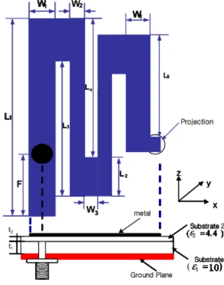
Fig. 1 shows the geometry of the proposed antenna. The proposed antenna was based on modified meander-line techniques and the bowtie-shaped model, which resulted in a wide bandwidth that covered the 5-GHz band. L and W are the length and the width of the proposed model, respectively. t1 and t2 are the thicknesses of the board and the air gap, while F is the distance from the starting point to the feed point on the meander-line.We inserted the projection in a half-bowtie-shaped meander patch model for impedance matching. The width and length of the
projection were 2 mm and 2.3 mm, respectively.
Owing to the use of a coaxial feed line and the narrow width (11 mm in this study) of the meander patch, the proposed antenna could easily fit into any narrow space within a communications device, as, for example, the narrow space between the liquid crystal display panel and the housing of a laptop.
The proposed antenna was constructed by making a meander patch in a perfectly conducting plane, supported by a dielectric substrate with a thickness of 0.8 mm and a relative dielectric constant of 4.4.
The antenna was excited by means of a 50-coaxial feed. An air-layer substrate, with a thickness of 4.8 mm, existed between the FR4 substrate and the ground plane. A grounded conducting plate with dimensions of 40 40 mm2 was used in the experiment to approximate the infinite ground plane.
An antenna's structure is generally based on the optimized values derived from a simulation, with the required characteristics obtained bytuning. This paper conducted standard simulation, production, and measurement, with the optimized values were attained by trading off various parameters. To prove that the values were the optimized values, the paper presented the results according to thechanges of the various parameters with figures. The antenna was then designed using optimal conditions.
2
Substrate
) 4 . 4 ( ε =
1.0 ) ε =
) 4 . 4
( =
1.0 )
=
t1
) 4 . 4 (
2=
1.0 )
=
Substrate
) 4 . 4
( =
1.0 )
1
= L
1L
3L
4L
2L
5W
13
W
21
x z
y
Substrate
) 4 . 4 ( ε =
1.0 ) ε =
) 4 . 4
( =
1.0 )
= ) 4 . 4 (
2=
1.0 )
=
metal
Substrate
Ground Plane
) 4 . 4
( =
1.0 ) (
1= L
1L
3L
4L
2L
5W
1W
32
x z
y x z
y
t2
W
1W
1Projection
F
Fig. 1. Configuration of the modified bowtie-shaped
meander-type patch antenna
그림 1. 수정된 보우타이형 미앤더 패치 안테나
2.1 Width of W1
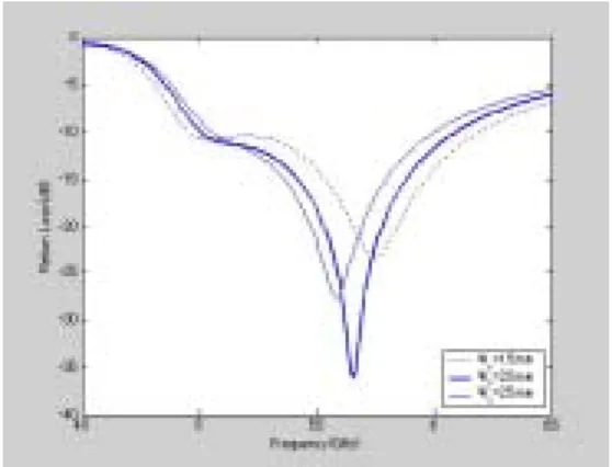
According to the variations of W1, the width of the meander line was from 1.5 mm to 2.5 mm and the return loss is analyzed in Fig. 2. It can be seen that with an increase in W1, the operating frequency of the proposed antenna shifted to lower frequencies. When the W1 was equal to 1.5 mm, the bandwidth of the proposed antenna was its best characteristic but its return loss was its worst characteristic. The good characteristic of return loss as a compromise between bandwidth and matching was obtained at W1 = 2.0 mm.
Fig. 2. Influence of the width of W1 on the return loss of the proposed antenna (L1 = 20.6 mm, L2 = 4.3 mm, L3 = 14.3 mm, L4 = 12.8 mm, L5 = 12.3 mm, W2 = 1.0 mm, W3 = 1.0 mm, other meander line widths = 1.0 mm, and
F = 5.2 mm, t1 = 4.3 mm)
그림 2. W1 에 따른 제안된 안테나의 반사손실(L1 = 20.6 mm, L2 = 4.3 mm, L3 = 14.3 mm, L4 = 12.8 mm, L5 = 12.3 mm, W2 = 1.0 mm, W3 = 1.0 mm, other meander line widths = 1.0 mm, and F = 5.2 mm, t1 = 4.3 mm)
2.2 Width of W2
Fig. 3 shows the simulation results of W2, the width of the lines. According to the variation of W2from 0.5 mm to 1.5 mm, the return loss was transferred to lower frequencies. When W2 was equal to 2.0 mm, the characteristic of the return loss was the best but the characteristic of the bandwidth did notcover the 5.2-GHz band. The optimum value of W2 appeared to be 4.5 mm at the desired operational frequency.
Fig. 3. Influence of the width of W2 on the return loss of the proposed antenna (L1 = 20.6 mm, L2 = 4.3 mm, L3 = 14.3 mm, L4 = 12.8 mm, L5 = 12.3 mm, W2 = 1.0 mm, W3 = 1.0 mm, other meander line widths = 1.0 mm, and
F = 5.2 mm, t1 = 4.3 mm)
그림 3. W2 에 따른 제안된 안테나의 반사손실 (L1 = 20.6 mm, L2 = 4.3 mm, L3 = 14.3 mm, L4 = 12.8 mm, L5 = 12.3 mm, W2 = 1.0 mm, W3 = 1.0 mm, other meander line widths = 1.0 mm, and F = 5.2 mm, t1 = 4.3 mm)
2.3 Width of W3
Fig. 4 shows the simulation results of W3, the width of the lines. According to the variation of W3 from 0.5 mm to 1.5 mm, the return loss was transferred to lower frequencies. When W3 was equal to 1.5 mm, the characteristic of the return loss was the best characteristic but the characteristic of the bandwidth did not cover the 5.2-GHz band. The optimum value of W3 appeared to be1.0 mm at the desired operational frequency.
Fig. 4. Influence of the width of W3 on the return loss of
the proposed antenna (L1 = 20.6 mm, L2 = 4.3 mm, L3 = 14.3 mm, L4 = 12.8 mm, L5 = 12.3 mm, W1 = 2.0 mm, W2 = 1.0 mm, other meander line widths = 1.0 mm, and
F = 5.2 mm, t1 = 4.3 mm)
그림 4. W3 에 따른 제안된 안테나의 반사손실(L1 = 20.6 mm, L2 = 4.3 mm, L3 = 14.3 mm, L4 = 12.8 mm, L5 = 12.3 mm, W1 = 2.0 mm, W2 = 1.0 mm, other meander line widths = 1.0 mm, and F = 5.2 mm, t1 = 4.3 mm)
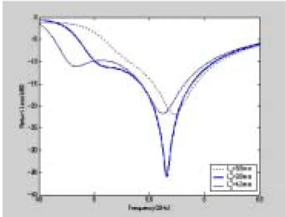
2.4 Length of L1
Fig. 5 shows the simulation results of L1, the length of the lines. According to the variation of L1 from 19.6 mm to 21.6 mm, the characteristic of the return loss was transferred to lower frequencies.
The best characteristic of the return loss was obtained at L1 = 20.6 mm
Fig. 5. Influence of the width of L1 on the return loss of the proposed antenna (L2 = 4.3 mm, L3 = 14.3 mm, L4 = 12.8 mm, L5 = 12.3 mm, W1 = 2.0 mm, W2 = 1.0 mm, W3 = 1.0 mm, other meander line widths = 1.0 mm, and
F = 5.2 mm, t1 = 4.3 mm)
그림 5. L1 에 따른 제안된 안테나의 반사손실(L2 = 4.3 mm, L3 = 14.3 mm, L4 = 12.8 mm, L5 = 12.3 mm, W1 = 2.0 mm, W2 = 1.0 mm, W3 = 1.0 mm, other meander line
widths = 1.0 mm, and F = 5.2 mm, t1 = 4.3 mm)
2.5 Length of L2
Fig. 6 shows the simulation results of L2, the length of the lines. According to the variation of L2 from 3.3 mm to 4.3 mm, the return loss was transferred to lower frequencies. When L2 was equal to 4.3 mm, the characteristic of the bandwidth did not cover the 5.2-GHz band. The best characteristic of the return loss was obtained at L3
= 3.8 mm.
Fig. 6. Influence of the length of L2 on the return loss of the proposed antenna (L1 = 20.6 mm, L3 = 14.3 mm, L4
= 12.8 mm, L5 = 12.3 mm, W1 = 2.0 mm, W2 = 1.0 mm, W3 = 1.0 mm, other meander line widths = 1.0 mm, and
F = 5.2 mm, t1 = 4.3 mm)
그림 6. L2 에 따른 제안된 안테나의 반사손실(L1 = 20.6 mm, L3 = 14.3 mm, L4 = 12.8 mm, L5 = 12.3 mm, W1 = 2.0 mm, W2 = 1.0 mm, W3 = 1.0 mm, other meander line
widths = 1.0 mm, and F = 5.2 mm, t1 = 4.3 mm)
2.6 Length of L3
Fig. 6 shows the simulation results of L3,the length of the lines. According to the variation of L2 from 13.3 mm to 15.3 mm, there was a slight change in the resonant frequencies, but the return loss was transferred to lower frequencies. When L3 was equal to 15.3 mm, the characteristic bandwidth was the best characteristic but the characteristic of the bandwidth did not cover the 5.8-GHz band. The best characteristic of the return loss was obtained at L3 = 14.3 mm.
Fig. 7. Influence of the width of L3 on the return loss of
the proposed antenna (L1 = 20.6 mm, L2 = 4.3 mm, L4 = 12.8 mm, L5 = 12.3 mm, W1 = 2.0 mm, W2 = 1.0 mm, W3 = 1.0 mm, other meander line widths = 1.0 mm, and
F = 5.2 mm, t1 = 4.3 mm)
그림 6. L3에 따른 제안된 안테나의 반사손실(L1 = 20.6 mm, L2 = 4.3 mm, L4 = 12.8 mm, L5 = 12.3 mm, W1 = 2.0 mm, W2 = 1.0 mm, W3 = 1.0 mm, other meander line
widths = 1.0 mm, and F = 5.2 mm, t1 = 4.3 mm)
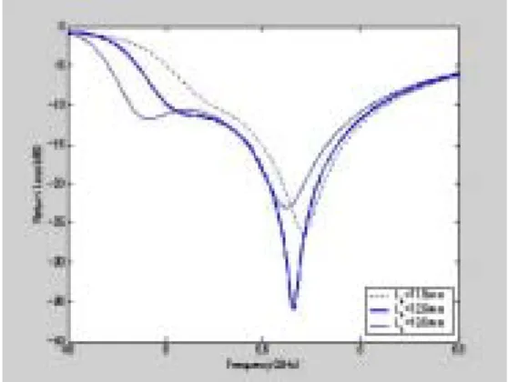
2.7 Length of L4
Fig. 8 shows the simulation results of L4, the length of the lines. According to the variation of L4from 11.8 mm to 13.8 mm, there was a slight change in the resonant frequencies, but the amplitude of the return loss changed sharply with the variation in the length of L4. When L4 was equal to 12.8 mm, the characteristic of the bandwidth was the best characteristic but it did not cover the 5.8-GHz band. The best characteristic of the return loss was obtained at L4 = 12.8 mm
Fig. 8. Influence of the length of L4 on the return loss of the proposed antenna (L1 = 20.6 mm, L2 = 4.3 mm, L3 = 14.3 mm, L4 = 12.8 mm, L5 = 12.3 mm, W1 = 2.0 mm, W2 = 1.0 mm, W3 = 1.0 mm, other meander line widths
= 1.0 mm, and F = 5.2 mm, t1 = 4.3 mm) 그림 8. L4에 따른 제안된 안테나의 반사손실(L1 = 20.6 mm, L2 = 4.3 mm, L3 = 14.3 mm, L4 = 12.8 mm, L5 =
12.3 mm, W1 = 2.0 mm, W2 = 1.0 mm, W3 = 1.0 mm, other meander line widths = 1.0 mm, and F = 5.2 mm, t1
= 4.3 mm)
2.8 Position of F
The correct position of the feed connection is obviously important, but is difficult to predict a
priori. Therefore, the simulation tool is used to determine the optimum feed position, as shown in Fig. 9. According to the variation of F from 4.7 mm to 5.7 mm, the return loss was transferred to lower frequencies. When F was equal to 4.7 mm, the characteristic of the bandwidth was the best characteristic but the characteristic of the return loss was not good. It was found that the good characteristic (as a compromise between bandwidth and match) is obtained when the feed is placed at a position of 5.2 mm.
2.9 Thickness of t1
Fig. 6 shows the simulation results of the thickness of t1,the height of the foam layer. As shown in Fig. 10, this parameter had a strong influence on the bandwidth and the band match of the antenna. The intermediate value of 4.3 mm was used as the best compromise to producing a 10-dB bandwidth of 19.05%.
Fig. 10. Influence of the width of t1 on the return loss of the proposed antenna (L1 = 20.6 mm, L2 = 4.3 mm, L3 = 14.3 mm, L4 = 12.8 mm, L5 = 12.3 mm, W1 = 2.0 mm, W2 = 1.0 mm, W3 = 1.0 mm, other meander line widths
= 1.0 mm, and F = 5.2 mm, t1 = 4.3 mm) 그림. 10. t1에 따른 제안된 안테나의 반사손실(L1 = 20.6 mm, L2 = 4.3 mm, L3 = 14.3 mm, L4 = 12.8 mm, L5 = 12.3 mm, W1 = 2.0 mm, W2 = 1.0 mm, W3 = 1.0 mm, other meander line widths = 1.0 mm, and F = 5.2 mm, t1
= 4.3 mm
2.10 Matching Projection
The last parameter to be explored using the
simulation is the size of the projection. As shown in
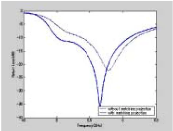
Fig. 11, although the total size of the patch increased, the characteristic of the return loss was good. A projection of the patch with dimensions of 2 2.3 mm2 was used in the experiment to match the impedance and produce a 10-dB bandwidth of 19.05%.
Fig. 11. Influence of the matching projection on the return loss of the proposed antenna
그림 11. 임피던스 정합기 설치에 따른 제안된 안테나의 반사손실
III. Experimental Results and Discussion
By using the described design procedure, a proposed antenna was constructed and tested to operate at the range of a 5-GHz WLAN system.
The simulated results were obtained with Ensemble 5.0, based on the methodof moment in the frequency domain. The line width, line length, gap of the lines, thickness of the foam, and position of the feeding point varied in steps, with the bandwidth calculated at each step until the maximum bandwidth was obtained and optimized for the WLAN system in the 5-GHz band. The optimum design parameters of the proposed antenna were set as follows: L1 = 20.6 mm, L2 = 4.3 mm, L3 = 14.3 mm, L4 = 12.8 mm, L5 = 12.3 mm, W1 = 2.0 mm, W2 = 1.0 mm, W3 = 1.0 mm, other meander line widths = 1.0 mm, and F
= 5.2 mm. An air layer with a spacing of t1 = 4.3 mm between the dielectric substrate and the ground plane was chosen for the experiment in order to minimize the return loss. After achieving the optimum design, the antenna was fabricated on Du-San Cooperation's DS-7408 T/C H/H substrate
with an 0.8-mm thickness and . Fig. 12 shows the fabricated bowtie-shaped meander-type patch antenna for the 5-GHz band. Fig. 13 shows the measured and simulated return losses. The return loss of the proposed antenna was measured with an HP8510 network analyzer from Inha University, with far-field patterns and gain measured inside a compact range available from the TIC of Incheon University. It was seen that the measured data agreed with thesimulated results obtained from the Ensemble 5.0 simulation software [11]. Two adjacent resonant frequencies, at 5.17 and 5.68 GHz, were observed, which were so close to each other that the overall impedance bandwidth (return loss < -10 dB) was markedly broadened.
The measured impedance bandwidth, defined by S11
= -10 dB, reached 1.055 GHz (5.01-6.065 GHz), thus covering the 5.2-GHz (5.15-5.35-GHz) and 5.8-GHz (5.725-5.875-GHz) bands for WLAN operation.
Regarding factors that caused discrepancies in the results of the simulation as compared with those of the measurement: first, the simulation confirmed that foam thickness greatly influences the characteristics of the antenna proposed in this paper, and it is believed that any minute difference in the foam thickness between the simulation and the actual production may have created such errors;
second, although Ensemble 5.0, a simulation tool
used in this paper, calculates the size of ground as
infinity, the size of the actual antenna ground is
finite, which may have caused errors; and third, the
position of the feed point plays a considerable role
in the characteristics of the antenna, and the error
between the feed point in the simulation and that in
the actual production may therefore have created
errors between the simulation results and the
measurement results. To reduce such errors,
therefore, it is advised to use a commercial tool that
offers a simulation mode with a finite ground
surface and/or to design a production process that
approaches the simulation values as close as
possible and is highly accurate and precise.
(a) top view
(b) side view
Fig. 12. Fabrication of a half-bowtie-shaped meander-type patch antenna for the 5-GHz band
그림 12. 제안된 안테나의 제작 형태 (a)정면도, (b)측면도
Fig. 13. Simulated and measured results of return loss against frequency for the proposed antenna 그림 13. 제안된 안테나의 반사손실에 대한 시뮬레이션 값과
측정값
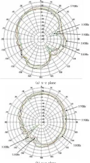
The radiation characteristics of the proposed antenna were also studied. Fig. 14 presents the measured radiation patterns for the free spaces at
5.2, 5.3, 5.5, 5.7, and 5.8 GHz in the x-z plane and the y-z plane, respectively. The red line represents the radiation pattern at 5.2 GHz, and the green, purple, black, and orange lines represent the radiation pattern at 5.3, 5.5, 5.7 and 5.8 GHz, respectively. The 3-dB beam-width (HPBW) in the x-z plane and the y-z plane were 66.70°and 68.18at 5.3 GHz, respectively. In the 5.8-GHz case, the 3-dB beam-width (HPBW) in the x-z plane and the y-z plane were 54.91?and 66.00? respectivel
(a) x-z plane
(b) y-z plane
Fig. 14. Radiation patterns of the proposed antenna at different frequencies in the operating band at the (a) x-z
plane and the (b) y-z plane
그림 14. 동작 주파수에서 몇 가지 주파수에 대한 제안된
안테나의 방사패턴 (a) x-z평면, (b) y-z 평면
Fig. 15 shows the simulated and measured antenna gains against the frequency for the proposed antenna. The antenna gain had a peak value of 8.86 dBi at 5.7 GHz. For the 5.3-GHz case, the maximum gain at the x-z plane was 5.37 dBi and at the y-z plane, 5.63 dBi. Also, for the 5.8-GHz case, the maximum gain at the x-z plane was 7.61 dBi and at the y-z plane, 7.46 dBi. It is generally acceptable to expect some discrepancies between the measurement and the simulation results, as each case's test conditions cannot be exactly identical. In particular, the ground condition in the simulation mode is based on the assumption that it is infinite,whereas the actual production uses a finite ground surface, resulting in different antenna characteristics when measured. In terms of the antenna's gains, the measurement results on the actual production show lower gains than those in the simulation results. Although the gain errors in this paper showed that the VSWR value went up thanks to the VSWR errors in the 5.2-GHz band, it is believed that the gain was merely reduced because the antenna was out of phase. It is therefore necessary that the distribution of the surface current should factor into the gain errors in future studies.
Fig. 15. Simulated and measured antenna gains for operating frequencies across the 5-GHz band 그림 15. 5-GHz 대역에 대한 이득의 시뮬레이션 값과
측정값
IV. Conclusion
In this paper, a half-bowtie-shaped meander-type antenna for 5-GHz band operation in WLAN communications has been proposed. By varying the meander line's width and length, a number in the meander section, and the bowtie-shaped length and position of the feeding point, optimizing parameters can be obtained for a small antenna. The proposed antenna for the 5-GHz band was constructed and tested. A prototype with a wide impedance bandwidth (-10 dB and below) of about 1.055 GHz (5.01-6.065 GHz) covering the 5-GHz band was successfully implemented. Across the 5-GHz band, good broadside radiation patterns were also observed. The measured antenna gain ranged from about 2.26 to 8.86 dBi. The proposed antenna is very promising for application in a WLAN for operation in the 5-GHz band.
References
[1] J. George, M. Deepukumar, C. K. Aanandan, P.
Mohanan, and K. G. Nair, "New compact microstrip Antenna", Electronics Letters, Vol. 32, No. 6, pp.508-509, March 1996.
[2] A. SerranoVaello and D. Sanchez-Hernandesz,
"Printed antennas for dual-band GSM/DCS 1800 mobile handsets", Electronics Letters, Vol. 34, No. 2, pp.40-141, January 1998.
[3] J. George, K. Vasudevan, P. Mohanan, and K. G.
Nair, "Dual frequency miniature microstrip antenna", Electronics Letters, Vol. 34, No. 12, pp.1168-1170, June 1998.
[4] K. L. Wong and W. S. Chen, "Slot-loaded bow-tie microstrip antenna for dual frequency operation", Electronics Letters, Vol. 34, No. 18, pp.1713-1714, 1998.
[5] J. F. Huang, C. W. Kuo, "CPW-fed bow-tie slot antenna", Microwave and Optical Technology Letters, Vol. 19, No. 5, pp.358-360, Dec. 1998.
[6] E. A. Soliman, S. Brebels, P. Delmotte, G. A. E.
Vandenbosch, and E. Beyne, "Bow-tie slot antenna fed by CPW, " Electron Letter Vol. 35, No., 514-515, Oct. 1999.
[7] G. Zheng, A. A. Kishk, A. W. Glisson, and A. B.
Yakovlev, "Slot Antenna fed by a CPW line with
tapered Transition", Microwave and Optical
Technology Letters, Vol. 38, No. 6, pp.465-467, Sep.
20 2003.
[8] P. T. Teo, K. S. Lee, Y. B. Gan, C. K. Lee,
"Development of bow-tie antenna with an orthogonal feed", Microwave and Optical Technology Letters, Vol. 35, No. 4, pp.255-257, Nov. 20 2002.
[9] M. Ali and S. S. Stuckly, "A Meander-line Bow-tie Antenna", 1996 IEEE Antenna and Propagation Soc International Symposium, pp.
1566-1569, June 1996.
[10] S. H. Wi, J. M. Kim, T. H. Yoon, H. J. Lee, J.
Y. Park, J. G. Yook, and H. K. Park, "Bow-tie shaped Meander Slot Antenna for 5GHz Application
", 2002 IEEE Antenna and Propagation Soc International Symposium, Vol. 2 , pp. 456-459, June 2002.
[11] Ensemble, Design User's Guide, Ansoft, USA, 1998.
저 자 소 개
안규철 (正會員)
1988년 : 인하대학교 전자공학과 졸업 (공학사)
1990년 : 인하대학교 대학원 전자공학과 (공학석사) 1996년 : 인하대학교 대학원 전자공학과 박사수료
1990년 ~ 1993년 LG정보통신 연구소 연구원 1993년 ~ 1995년 한국체육과학 연구원 스포츠공학실 연구원
1996년 ~ 현재 안산1대학 디지털정보통신과 부교수 (산학협력단장)
<주관심분야>
광통신, 광전자공학, 전자장이론, 안테나공학
李相睦(正會員)
1984년 2월 한국항공대학교 항공전자공 학과 졸업(공학사)
1986년 2월 한국항공대학교 항공전자공 학과 대학원 졸업(공학석사)
2003년 2월 인하대학교 대학원 전자공 학과 졸업 (공학박사)
1990년 3월 ~ 현재 : 재능대학 정보통 신과 교수
<주관심분야> 안테나 설계, 전자파해석, 광통신
尹中漢 (正會員)
제 4권 제 1호 논문 00-01-10 참조
2003년 2월 인하대학교 대학원 전자공학과 졸업 (공학박사) 2005년 11월 ~ 현재 삼성전기 책임연구원
金興壽(正會員)
제 3권 제 2호 논문 99-02-12 참조