Vol. 18, No. 6, pp. 207-214, December 2014
Study of Mass and Flow Resistance in a Square Ribbed Microchannel using Lattice Boltzmann Method
Mohammad Abu Taher*, Heuy-Dong Kim** and Yeon-Won Lee*†
(Received 03 November 2014, Revised 01 December 2014, Accepted 02 December 2014)
Abstract: Mass and flow resistance in a square ribbed microchannel have been studied numerically using the Lattice Boltzmann Method. It has been build up on two dimensional nine velocity vectors model with single relaxation time method called the Lattice Bhatnagor-Gross-Krook model. To analyze the roughness effect on the flow resistance namely the friction factor and mass flow has been discussed at the slip flow regime, 0.01≤Kn≤0.10, where Kn is the Knudsen number. The wall roughness is considered by square microelements with a relative roughness height up to maximum 10% of channel height. The velocity profiles in terms of streamlines near the riblets are demonstrated to be responsible for the roughness effect. It is found that the roughness effect leads to increase the flow resistance with roughness height but it is decreased significantly with increasing the space between two roughness elements as well as the Knudsen number. In addition, the mass flow decreased linearly with increasing both roughness height and gap but significantly changed at the slip flow regime.
Key Words:Lattice-Boltzmann, Knudsen Number, Surface roughness, Friction, Mass flow
*†Yeon-Won Lee (corresponding author): Department of Mechanical and Automotive Engineering, Center for Marine-Integrated Biomedical Technology, Pukyong National University, Busan, Korea.
E-mail : [email protected], Tel : 051-629-6162
*Mohammad Abu Taher: Department of Mechanical and Automotive Engineering, Pukyong National University, Busan, Korea.
** Heuy-Dong Kim: Department of Mechanical Engineering, Andong National University, Andong, Korea.
― Nomenclature ―
D : Hydraulic diameter [m]
d : Roughness Height [m]
ei : Discrete particle velocity vector[m/s]
Fi : Discrete particle distribution function
ieq
F : Equilibrium particle distribution function H : Height of the microchannel[m]
Kn = Knudsen number
L=Length of the microchannel[m]
P=Pressure [pa]
Pn : Poiseuille number
s=Distance between centers of two consequent riblets[m]
Greek Symbols
ρ : Density [kg/m3]
ε : Relative roughness height(%) τ : Relaxation time for momentum ν : Kinematic viscosity[m2/s]
1. Introduction
The roughness effect is one of the most important
factors in micro fluidics systems, especially in microchannel. At the microscale level, it is very difficult to obtain a completely smooth wall surface.
So the effect of surface roughness may cause for different characteristics between fluid flow in microchannel and that of in conventional channel1). In modeling of the roughness effect on rarefied gas flow in microscale system, Rovenskaya et al.2) and Khadem et al.3) have studied the same over rough surfaces with different approaches. Actually, in microchannel, the main effects are rarefaction effects, essentially quantified by the Knudsen number Kn. According to the Rarefied Gas Dynamics (RGD), Knudsen number is defined as Kn=λ/L, where λ is the gas mean free path and L is the characteristic length. It is investigated by many researchers4, 5) that surface roughness may have a significant impact on microchannel performances, both in terms of pressure drop and heat transfer. In their investigation, they used different approaches as well as different numerical schemes considering various types of rough surfaces with different relative roughness heights.
Nowadays, the Lattice Boltzmann Method (LBM), based on Boltzmann equation (BE), provides a new effective way to study the micro-gas flow system.
But, it is well known that the Lattice Boltzmann method (LBM) can faithfully be used to simulate the Navier-Stokes (N-S) equations with high accuracy and this lattice BGK (LBGK) model recovers the N–S macroscopic equations6,7). Many researchers8,9) applied this method in micro flows due to rapid advancement of micro electro mechanical system (MEMS). But in micromachining technology, the flow resistance or friction on surface roughness cannot be ignored. Using LBM, the effects of surface roughness on friction and flow analysis in microchannel, considering a series of rectangular shape rough elements, are discussed by some researchers10-12). In the present study, different
type of roughness geometry is taken to be considered in order to investigate the mass, flow and fluid resistance in terms of Poiseuille number (Pn) at the slip flow regime, 0.001<Kn <0.10, with relative roughness height from ε=0% to 10% and gap between roughness elements varying from 2%-3% of channel height. A few investigations of this type of fluid flow problem using LBM are found in the literature, but to the author’s knowledge, the above mentioned problem has not been considered yet. All flow parameters like velocity profiles, mass flow rate, fluid resistance and flow field near rough surfaces affected by the surface roughness and spacing between roughness elements at the slip flow regime are presented in the present study.
2. Formulation of the problem
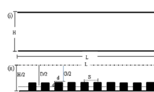
A schematic diagram of the rough microchannel with boundary conditions is shown in Fig. 1. The surface roughness is modeled by a series of square microelements that are distributed uniformly and symmetrically on the top and bottom walls boundary at a distance H=100μm from each other. The length L depends on the gap between two roughness elements.
Fig. 1 Schematic diagram of the simulation system (i) smooth channel and (ii) square ribbed rough microchannel.
The relative roughness, ε=d/H, varies from 0%
to10%, where d is the roughness height. The hydraulic diameter of the channel is defined by D
=(H+G)/2, G=H-2h, where G is the gap between pick position of two roughness elements at the top and bottom walls. Therefore, DH =H-h. S is the distance between centers of two consequent roughnesses. The gap ratios are considered S*=S/H=0.2 and 0.3, so the corresponding length became L=220 μm and 330 μm respectively. It is noted that, if the relative roughness height increased, the area of each roughness element also increased;
therefore the absolute gap between two riblets is decreased.
In micro-flow system, especially in the study of flow dependence on Knudesn number, including slip velocity, pressure drop in rough microchannel, the Lattice Boltzmann Method (LBM) can be effectively applied instead of conventional CFD method.
Because it is a kinetic method based on particle distribution functions,. Therefore, the Boltzmann Equation (BE) in terms of with BGK approximation can be defined as8):
) 1(
. i ieq
i i i
i F F
x e F t
F
, i=0,1,…,8 (1)
Where,is the discrete equilibrium distribution function at lattice position and time t discussed and defined by6-8). The total number of discrete velocities (ei) on each node in D2Q9 model is 9.
The form of this equilibrium distribution function must be chosen so that the fluid mass and momentum are conserved. For two dimensional D2Q9 model, the equilibrium distribution function is defined by6-8) as the following way:
2 ] 3
) . 2 ( . 9 1 3 [
2 2
2 4 2
eq i eq i eq
eq i i
c u
u c e u c e w F
(2)
Here c is known as CFL number. Therefore the discrete form of equation (1) is called the Lattice- Boltzmann equation (LBE) and can be defined as
) 1(
) , ( ) , (
ieq i
i i
i
F F
t x F t t e t x F
(3)
Here ω =1/τ is the relaxation parameter that depends on the local macroscopic variables ρ and .These variables should satisfy the following laws of conservation:
i
Fi
,
i i iF e u
(4)
The equation (4) describes the relationships between the microscaled quantities and the macro scaled physical quantities. The above equations (1)-(4) are the working horse of the lattice Boltzmann method.
In micro-flows, the local density variation is still relatively small, but the total density changes, for instance the density difference between the inlet and outlet of a very long channel could be quite large.
In order to account for this density variation and its effect on the kinematic viscosity ν, Niu et al.9) proposed a new relaxation timeτ’ in place of τ in equation (3) as:
2 1 2 1
1
(5)
In previous lattice-BGK models, the relaxation time τ was chosen to be a constant during the computational procedure. This is applicable only for nearly-incompressible fluids. To include the dependence of viscosity on density we replace τ by τ’ in Eq. (3) and it is very important to calculate the micro-scale fluid flow problems.
3. Results and discussion
3.1 Boundary conditions
The microscopic flows are usually characterized by the Knudsen number, Kn, defined as the ratio λ /H, where λ is the mean free path and H is the characteristics length.
Re Ma Kn 2
H (6)
Where is the specific heat ratio, Ma is the Mach number and Re is the Reynolds number. The Reynolds number is considered based on the characteristic length and the maximum incoming flow velocity as well as the nature of fluid transport properties. In order to simulate a fully developed laminar channel flow upstream of the main cylinder, a parabolic velocity profile can be used at the inlet and outlet with a maximum velocity U at the midpoint of the channel. A series of computations carried out at a pressure ratio Pi/Po =1.4, 1.3 and 1.2 for Kn= 0.02, 0.05 and 0.10 respectively, where Pi and Po are the inlet and out pressure respectively.
In LBM, it cannot be used macroscopic variables directly, so the inlet and exit pressure conditions are used with the help of very simple equilibrium rules to the particle distribution functions. At the top and bottom wall, slip velocity boundary conditions are imposed by the standard bounce back treatment in order to eliminate the effect of compressibility9-10). Throughout this study, the lattice units are considered. The computations were carried out with a code developed by the authors and written in FORTRAN language.
3.2 Validation of the method
To investigate the roughness effect on flow characteristics, it is very essential to calculate the flow resistance, especially for microchannel flow.
Actually, the flow resistance is defined of how flow
is related to pressure drop, viscosity, radius and length of the system. Therefore, the friction f is defined as an average value either over a portion of rough section of the channel or over a single geometrically periodic roughness element. The product of the friction factor f and the Reynolds number Re is often referred to as the flow resistance or friction constant, called Poiseuille number, Pn= f Re. The Poiseuille number Pn is then written in terms of local Re defined by12):
f u
D2
L P Re 2
Pn
(7)
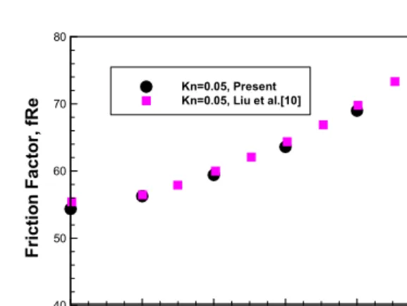
Where D is the hydraulic diameter, defined in section 3, the variations ∆P and ∆L are computed between the inlet and outlet section, and are the cross sectional average value. To verify our results with the conventional benchmark, the friction factor fRe in terms of Poiseuille number Pn at Kn=0.05 with relative roughness height as shown in Fig. 2.
For verification, it is considered that the rectangular shape roughness elements uniformly distributed at the top and bottom walls. A good agreement is seen between the present solution and bench mark solution of Liu et al.10).
0 2 4 6 8 10
40 50 60 70 80
Kn=0.05, Present Kn=0.05, Liu et al.[10]
Relative Roughness Height (%)
FrictionFactor,fRe
Fig. 2 Average fRe at Kn=0.05 for different relative roughness height for rectangular roughness microchannel.
3.3 Mass flow Analysis
Another important study of interest is the mass flow rate due to its applications in rough microchannel of gaseous flow. The average mass flow rate is calculated from numerical results using the following expressions by Chai et al.12).
H
dy H u
0
Q 1 (8)
It can be normalized by ρ0UH2, where ρ0, U and H are characteristics density, velocity and height respectively.
0 2 4 6 8 10
7.70E-04 7.80E-04 7.90E-04 8.00E-04
smooth(no riblets) square riblets
MassFlowRate
Roughness Height,
Fig. 3 Comparison of mass flow rate with smooth channel with relative roughness height.
0 0.02 0.04 0.06 0.08 0.1 0.12
6.00E-04 7.00E-04 8.00E-04 9.00E-04 1.00E-03
smooth
square riblets(4%)
Kn
MassFlowRate
Fig. 5 Comparison of mass flow rate with smooth channel at the slip flow regime.
0 2 4 6 8 10
6.00E-04 7.00E-04 8.00E-04 9.00E-04 1.00E-03
s=0.2H, Kn=0.02 s=0.3H, Kn=0.02 s=0.2H, Kn=0.05 s=0.3H, Kn=0.02 s=0.2H, Kn=0.10 s=0.3H, Kn=0.10
MassFlowRate
Roughness Height (%)
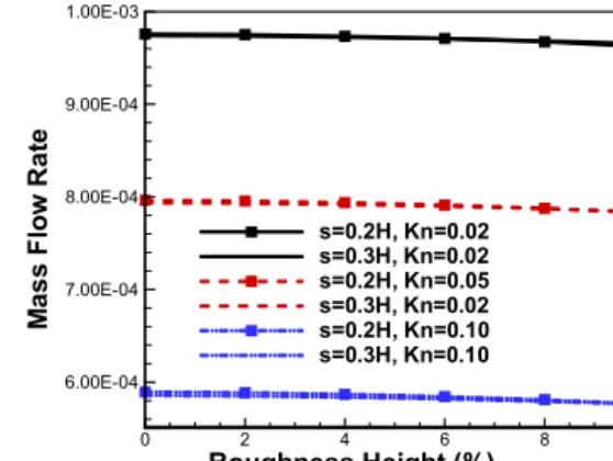
Fig. 4 Mass flow rate with roughness height for s=0.2H and s=0.3H.
The effect of surface roughness height, spacing of square microelements and Knudsen number on the average mass flow rate are is described in Figs.3-5.
It is seen from Fig.3 that the less mass flow occurred thorough rough microchannel compare to smooth channel. However, the mass flow rate decreased linearly and very slightly with increase the roughness height and gap as shown in Fig.4. It is remarkably changed at the slip flow regime as shown in Fig.5.
3.4 Friction or flow resistance effect
0 2 4 6 8 10
30 60 90 120 150 180 210 240
smooth,Kn=0.02 rough, Kn= 0.02 smooth,Kn=0.05 rough, Kn= 0.05 smooth,Kn=0.10 rough, Kn= 0.10
FrictionFactor,fRe
Roughness Height,
Fig. 6 Comparison of flow resistance with smooth channel for different relative roughness height at Kn=0.02, 0.05 and 0.10.
0 2 4 6 8 10 30
60 90 120 150 180
210 s=0.2H, Kn=0.02
s=0.3H, Kn=0.02 s=0.2H, Kn=0.05 s=0.3H, Kn=0.02 s=0.2H, Kn=0.10 s=0.3H, Kn=0.10
FrictionFactor,fRe
Roughness Height (%)
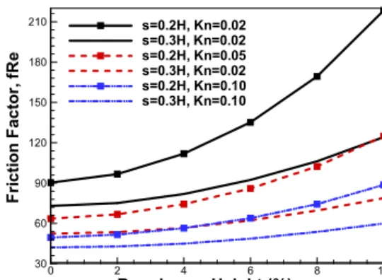
Fig. 7 Average flow resistance with roughness height for s=0.2H and 0.3H at Kn=0.02, 0.05 and 0.10.
0 0.02 0.04 0.06 0.08 0.1 0.12
40 60 80 100 120
smooth square riblets(2%) square riblets(4%)
Kn
FrictionFactor,fRe
Fig. 8 Average flow resistance at the slip flow regime with roughness height ε=2% and 4%, s=0.2H.
To analyze the flow resistance or friction in a rough microchannel, Poiseuille number is one of the most important parameter, details in section 3.2. The effects of flow resistance at slip flow regime, 0.01
≤Kn≤0.10, with relative roughness height from 0%-10% and gap, s=0.2H and 0.3H, are shown in Figs.6-8. Fig. 6 illustrated the effect of flow resistance with roughness height for Kn=0.02, 0.05 and 0.10. The straight lines represent for smooth channel where as the symbol lines represent the rough microchannel. The constant frictions are observed for smooth channel but for rough channel, it is increased with roughness height. This is
because the roughness height may cause to increase the pressure drop. For very low roughness height, ε
≤ 2%, the flow resistance is negligible. Moreover, the gap between two riblets plays an important role for flow resistance. It is seen from Fig. 7 that the flow resistance decreased with increasing the gap between two consequent riblets. Form all of the above figures, in more specific, Fig. 8, the flow resistance is significantly decreased with increasing the Knudsen number due to the effect of higher slip wall velocity.
3.5 Flow field analysis
Figs. 9-10 illustrated the enlarged view of flow near the surface roughness at the middle of the channel in order to investigate the effect of average roughness geometry on the flow filed.
Fig. 9 Streamlines with vectors for s=0.2H and 0.3H at Kn=0.02 with fixed roughness height.
Fig. 10 Streamlines near the rough surface for different Kn with s=0.2H and ε=4%.
In Fig. 9, it is seen that the flow is influenced by the gap between the roughness elements and the recirculation is observed in the gap. The fluid velocity and strength of recirculation is stronger if the gap is smaller. In Fig. 10, it is investigated the flow effects at the slip flow regime. It is seen that the flow field is more affected at the lower Kn compare to higher Kn with same conditions. This is obvious because higher Kn means the higher slip at the wall.
4. Conclusions
The fluid flow resistance namely friction factor, the average mass flow rate and flow characteristics through a square ribbed microchannel have been discussed in the present study using the Lattice Boltzmann Method (LBM). It may conclude that the microchannel rough surfaces within the limit of relative roughness height and gap may cause the statistical changed of flow behaviors at the slip flow region, 0.01≤Kn ≤0.10, and consequently the mass flow rate and friction factor changed with them. It is seen that lower mass flow and higher friction are occurred in a rough microchannel compare to smooth channel. With increasing Knudsen number, both mass flow and flow resistance decreased significantly. However, they are decreased and increased linearly with increasing relative roughness height. It is noted that, the flow resistance significantly changed with gap between two roughness elements but the average mass flow rate change very slightly with it. Further study is needed to investigate the thermal performance on surface roughness geometry, height and gap in microchannel flow at the slip flow regime using LBM.
Acknowledgement
This work was supported by a Research Grant of
Pukyong National University (2014 year).
References
1. B-Y. Cao, M. Chen and Z-Y Guo, 2006, “Effect of surface roughness on gas flow in microchannels by molecular dynamics”, Int. J.
Engineering Science, Vol. 44, pp.927 - 937.
2. O. Rovenskaya and G. Croce, 2013, “Numerical investigation of microflow over rough surfaces:
coupling approach”, Journal of Heat Transfer, Vol. 135, pp.101005-1-101005-8.
3. M. H. Khadem, M. Shams and S. Hossainpour, 2009, “Effects of rarefaction and compressibility on fluid flow at slip flow regime by direct simulation of roughness”, Int. J. Aerospace and Mechanical Engineering, Vol.3, No.4, pp.
204-210.
4. G. Croce and P. D’Agaro, 2004, “Numerical analysis of roughness effect on microtube heat transfer”, Superlattices and Microstructures, Vol.35, pp.601-616.
5. Y.Ji, K. Yun and J.N.Chung, 2006, “Numerical simulation of wall roughness on gaseous flow and heat btransfer in a microchannel”, Int. J. Heat and Mass Transfer, Vol.49, pp.1329-1339.
6. X. Wei, K. Mueller and A. E. Kaufman, 2004,
“The lattice Boltzmann method for simulating gaseous Phenomena”, IEEE Transactions on Visualization and computer Graphics, Vol.10, No.02, pp.164-176.
7. H. Chen, S. Chen and W. H. Matthaeus, 1992,
“Recovery of the Navier-Stokes equations using a lattice-gas Boltzmann method”, Physical Review A, Vol. 45, No.8, pp. 5339-5342.
8. S. Chen and Z. Tian, 2009, “Simulation of microchannel flow using the lattice Boltzmann method”, Physica A, Vol.388, pp.4803-4810.
9. X. D. Niu, C. Shu and Y. T. Chew, 2007, “A thermal lattice Boltzmann model with diffuse
scattereing boundary condition for micro thermal flows”, Computers and Fluid, Vol.36, pp.273-281.
10. C. Liu, J. Yang and Y. Ni, 2011, “A multiplicative decomposition of Poiseuille number on rarefaction and roughness by lattice Boltzmann simulation”, Computers and Mathematics with Applications, Vol.61, pp.3528-3536.
11. S. H. Kim and H. Pitsch, 2008, “Slip velocity and Knudsen layer in the lattice Boltzmann method for microscale flows”, Physical review E, Vol.77, pp.026704-1-026704-12.
12. Z. Chai, Z. Guo, L. Zheng and B. Shi, 2008,
“Lattice Boltzmann simulation of surface roughness effect on gaseous flow in a microchannel”, J. Applied Physics, Vol.104, pp.014902-1-014902-8.
13. L. Chao-Feng and N. Yu-Shan, 2008, “The effect of surface roughness on rarefied gas flow by lattice Boltzmann method”, Chinese Physics B, Vol. 17, No.12, pp.4554-4561.
14. M. A. Taher, H.D. Kim, C.S. Kang and Y. W.
Lee, 2014, “Friction and flow analysis of square and circular riblets rough microchannels using LBM”, Proce. of the 5th Asian Workshop on Thermophysics and Fluid Science, Nagasaki, Japan, KA-27.