논문 2012-49TC-6-13
릴레이 주파수재사용을 위한 하향링크 전력 자원 할당
( Downlink Power Allocation for Relay Frequency Reuse )
오 창 윤**
( Changyoon Oh )
요 약
릴레이 간섭채널에서 하향링크 용량 극대화를 위한 전력할당 최적화 방안을 다룬다. 제 1 시간자원 영역에서 기지국은 단말 과 릴레이 기지국에 직교채널을 통해서 전력전송을 한다. 제 2 시간자원 영역에서 기지국과 릴레이 기지국은 서로에게 간섭 을 일으키면서 각각의 단말에게 전력을 전송한다. 본 논문에서 얻어진 전력 할당 최적화 방안은 제 2 시간자원 영역에서의 간 섭 레벨이 낮을 경우, 기지국과 릴레이 기지국의 동시 전력전송을 허용하고, 반면에 간섭레벨이 높을 경우, 릴레이 기지국의 전력전송을 차단한다.
Abstract
We consider the optimum power allocation problem for downlink system throughput maximization in a 2 time slotted relay interference channel. Base station (BS) transmits power to Mobile Station (MS) and Relay Station (RS) in time slot 1 (orthogonal channel). In time slot 2, BS and RS transmit power to each MS, while causing cochannel interference to each other. The obtained optimum power allocation scheme allows simultaneous transmissions of BS and RS when the interference level in time slot 2 is low. However, when the interference level is high, RS shuts down its power. Numerical results are provided to support our analysis.
Keywords: Relay, Interference Channel, Power Allocation, Frequency Reuse
Ⅰ. Introduction
Recently, research efforts have been focused on the issue of relay in cellular systems.[1, 3] Assuming half Duplex mode, relay operation requires additional resource. For example, IEEE Std 802.16j Relay Specification defined that the physical layer frame structure includes additional time zone for relay link[2]. Due to additional resource expense, to get the true benefit from relay operation, resource reuse plays a role of throughput enhancement. This resource reuse includes simultaneous transmissions of
* 정회원, 인하공업전문대학 정보통신과 (Inha Technical College, Information &
Communications Department)
접수일자: 2011년10월25일, 수정완료일: 2012년6월14일
BS and RS on the same channel, while causing cochannel interference to each other.
In this contribution, we investigate the optimum power allocation problem for downlink throughput maximization. With the consideration of Relay frame structure defined in IEEE Std 802.16j Specification, we model 2-time slotted system. More specifically, in time slot 1, BS transmits power to MS1 and RS through the orthogonal channel. In time slot 2, through the interference channel, BS transmits power to MS1 and RS transmits power to MS2 in order to relay the data received from BS in time slot 1. By intuition, simultaneous transmission is preferred when the interference level is low. In this contribution, to validate th intuition, we propose the optimum
transmission strategy to improve the throughput enhancement.
The obtained optimum power allocation scheme allows simultaneous transmissions when the interference level is below the specific level. On the other hand, when the interference level is beyond that level, the optimum strategy allows BS transmission only.
Ⅱ. SYSTEM MODEL AND PROBLEM FORMULATION
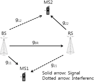
We consider a single cell system with a BS and a RS as in Figure 1 where solid arrow and dotted arrow represent signal and interference, respectively.
Figure 2 represent 2 time slot system with transmit power.
In time slot 1, BS with maximum power budget
allocates power to MS1(user 1) and RS(user 2), such that ≤ where denotes the allocated power for user . In time slot 2, BS and RS each with maximum power budget allocates power to MS1(user 3) and MS2(user 4), respectively, such that ≤ and ≤ .
The signal to interference ratio at the receiver side of user is expressed as
그림 1. 시스템 모델
Fig. 1. System Model with channel gain.
(1)
where denotes the channel gain from BS ( ) or RS ( ) to MS .
We denote as channel gain from BS to RS.
denotes the sum of the thermal noise and other interference for user .
We define the utility of user as follows:
(2)
where denotes the natural logarithm.
Utility is the achievable rate. We denote the factor
, capturing the gap, which is derived from the target bit error rate(BER),
[4]. By the assumption of orthogonal channel in time slot 1, i.e.,
, sum of the individual utility for MS1 and RS is as follows:
(3)
In time slot 2, sum of the individual utility for MS1 and MS2, is as follows:
그림 2. 2 슬럿 시스템 Fig. 2. 2-time slot System.
(4)
The system utility, i.e., sum of utilities for MS1 and MS2 in two time slot duration, is as follows:
(5)
Note that is not included in (5) because it is the utility to be relayed for the transmission in time slot 2.Formally, the optimization problem is formulated as:
(6)
≥
(7)
≤ ≥
(8)
≤ ≤
(9)
(7) implies that transmission rate of RS in time slot 2 can not exceed reception rate of RS in time slot 1.
In general, (6) is not convex, so it does not appear to be easy to solve.
Ⅲ. OPTIMUM TRANSMIT STRATEGY AND POWER ALLOCATION
A. Time Slot Wide Approach
By examining the behavior of (3), (4) and (5) under constraints (7), (8) and (9), we observe that the followings hold.
Observation III.1.
Suppose is the optimum power allocation, then in time slot 1.
This is obvious. Because both and are increasing concave.
Proposition III.2
Suppose is the optimum power allocation, then .
Proof:
Suppose ≥.Consider another power allocation in time slot 1, i.e.,
where , such that .
By noting that
which contradicts is the optimum power allocation.
Proposition III.2 implies that RS should relay (or transmit) all the received data received from BS in the optimum transmission strategy.
Proposition III.3
Suppose is the optimum power allocation. Then, either or holds in time slot 2. More specifically,
when
(i.e.
) (10)
when
(i.e.
) (11)
where
and
are SIRs of and , respectively, and
. proof:
From the fact that for
, can be increased until either
or meets. More specifically, by Proposition (III.2),
holds.
Case-I: Consider the case of , i.e.,
.
Suppose the optimum solution is such that
.
Then,
.
This means , i.e., exceeds maximum power budget.
Hence, ≠. That is, for the case of
.
Case-II: Similarly, consider the case of , i.e.,
. Suppose the optimum solution
is such that .Then,
. This means , i.e.,
exceeds maximum power budget.
Hence, ≠. That is for the case of
.
By Proposition III.3, (6) can be factored by two in terms of , (i.e., and ) as described in the next section.
In Proposition III.3, implies SIR at RS (where the BS’s transmit power level is
) in time slot 1.
means SIR at MS2 (where the BS’s and RS’s transmit power levels are ) in time slot 2.
Proposition III.3 implies that the optimum transmit power level can be obtained by simply comparing and .
B. System Wide Approach
Let us write the system utility, , in terms of allocated power for user 2, i.e., after replacing
by and taking out as
following:
(12)
≤ ≤
(13)
(14)
≤ ≤
(15)
where
,
, and
. (12) is derived from the case of in proposition (III.3). In this case,
. Similarly, (14) is derived from the case of in proposition (III.3). In this case,
. When , the optimum power allocation is obtained by solving only (12). Otherwise, (14) also should be solved. In order to find the optimum power allocation, we should search over all possible boundary points ( , , and ) and extreme points
for each
case, i.e., (12) and (14). The derivative of is
(16)
Since E is always positive,
is equivalent
to . Let be the
extreme point for ( ≤ ≤ ) and let
be the extreme point for ≤ ≤. By comparing the system utility of (12) and (14) for each extreme point and boundary point and selecting the largest, the optimum power allocation can be obtained.
More specifically, the optimum power allocation is as following:
when
(17)
when
IV. NUMERICAL RESULT
As Figure 3, distance between BS and RS is 700m and the distance between BS and MS1 is 200m.
Channel gain is modeled as
where
denotes the distance. WATTS.
WATTS. Factor k is 0.5.
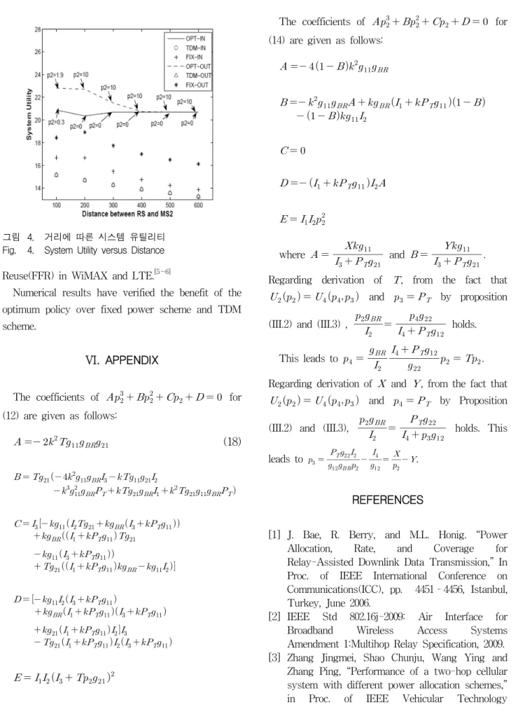
Figure 4 compares the system utility of different power allocation schemes i.e., Optimum scheme in (17), TDM scheme, and Fixed power scheme for a range of distance between RS and MS2. IN and OUT indicate that MS1 is on the righthand side and on the lefthand side from the BS, respectively. OPT, TDM, and FIX denote Optimum Scheme, TDM Scheme, Fixed Power Scheme, respectively. In TDM scheme, BS transmits full power, in a round robin fashion to MS1 and MS2 through time slot 1 and time slot 2, i.e. no Relay. In Fixed power scheme, equal power is assigned to MS1 and RS in time slot 1. In time slot 2, each BS and RS transmits full power to MS1 and MS2, respectively.
Two scenarios are investigated with the consideration of MS1's location. In other words, one scenario is the case when MS1 is located in the lefthand side of BS. In this case, MS1 receives weak cochannel from RS.
그림 3. 2 가지 시나리오 Fig. 3. 2 Scenarios.
Thus, the optimum power allocation of user 2, is .
The other scenario is the case when MS1 is located in the righthand side of BS. In this case, MS1 receives relatively strong interference from RS. Thus, the optimum power allocation of user 2, i.e., is
for a range of MS2's distance.
Optimum scheme shows significant gain in system utility, while sacrificing fairness. Note that when
, MS2 is not supported. For Optimum scheme and Fixed power scheme, the scenario of left hand side, thanks to low cochannel interference, shows higher system utility than that of righthand side. For TDM scheme, where no cochannel interference exists, both scenarios have identical system utility.
V. CONCLUSION
We have characterized the optimum power allocation policy for downlink throughput maximization on the relay enabled 2 time slotted system. More specifically, we took the approach of examining the system utility in terms of allocated power for RS.
The optimum policy shows that when the interference level is below the specific level in time slot 2, simultaneous transmissions from BS and RS are preferred. On the other hand, when the interference level is strong, single transmission is preferred. Conceptually, the philosophy of the obtained strategy is in line with Fractional Frequency
그림 4. 거리에 따른 시스템 유틸리티 Fig. 4. System Utility versus Distance Reuse(FFR) in WiMAX and LTE.[5~6]
Numerical results have verified the benefit of the optimum policy over fixed power scheme and TDM scheme.
VI. APPENDIX
The coefficients of for (12) are given as follows:
(18)
The coefficients of for (14) are given as follows:
where
and
. Regarding derivation of , from the fact that
and by proposition (III.2) and (III.3) ,
holds.
This leads to
. Regarding derivation of and , from the fact that
and by Proposition (III.2) and (III.3),
holds. This leads to
.
REFERENCES
[1] J. Bae, R. Berry, and M.L. Honig. “Power Allocation, Rate, and Coverage for Relay-Assisted Downlink Data Transmission,” In Proc. of IEEE International Conference on Communications(ICC), pp. 4451–4456, Istanbul, Turkey, June 2006.
[2] IEEE Std 802.16j-2009: Air Interface for Broadband Wireless Access Systems Amendment 1:Multihop Relay Specification, 2009.
[3] Zhang Jingmei, Shao Chunju, Wang Ying and Zhang Ping, “Performance of a two-hop cellular system with different power allocation schemes,”
in Proc. of IEEE Vehicular Technology
저 자 소 개 오 창 윤(정회원)
1999년 연세대학교 전기공학과 학사 졸업
2001년 Pennsylvania State University, Electrical Engineering 석사 졸업 2005년 Pennsylvania State
University Electrical Engineering 박사 졸업 2005년~2011년 삼성전자 DMC연구소
책임연구원
2011년~현재 인하공업전문대학 정보통신과 교수
<주관심분야 : Air Interface PHY/MAC 표준화, Resource Management, Frame Structure, Interference Alignment>
Conference(VTC). pp. 4538-4542, Los Angeles, U.S.A, Fall 2004.
[4] A. J. Goldsmith and S. G. Chua, “Variable-rate variable-power MQAM for fading channels,,”
IEEE Transactions on Communications, 45:1218-1230, October, 1997.
[5] IEEE Std 802.16-2009 Air Interface for Broadband Wireless Access Systems, November, 2009.
[6] http://www.3gpp.org/LTE.