,
,
, 40
PIV measurement on flow characteristics behind a Tetrapod in uniform flow
Ok-Sok G IM * and Kyeong-Woo L EE
1Ministry of Land Transport and Maritime Affairs, Mokpo branch office 1101 okam-dong, Mokpo, 530-831, Korea
1
Division of Ocean System Engineering, Mokpo National Maritime University, Mokpo, 530-729, Korea
Costal regions in Korea often suffer severe damages due to wave-induced disasters, storm surge disasters and so on. therefore, many engineers and researchers have devoted their energy to prevent these costal disasters. The development of artificial reefs including sunken vessels is one of their remarkable achievements and various kind of these artificial upwelling structures have been designed and applied.
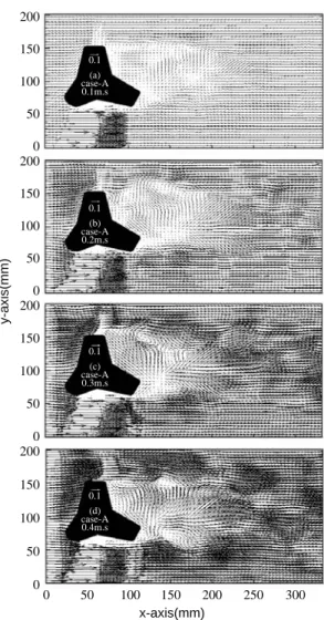
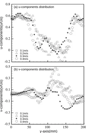
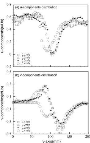
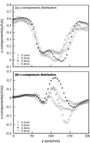
However, the flow characteristics around a Tetrapod under the water has not been investigated experimentally. So in this article, in uniform flow of circulating water channel and some different velocities, PIV measurement has been conducted on the flow characteristics behind a Tetrapod. The results were analyzed on the flow characteristics of both cases of a Tetrapod. Therefore, it can be concluded that the both cases have its own distinctive flow characteristics behind the bluff body; Case A has an steep upstream flow pattern. On the contrary, Case B has an developed downstream flow pattern in the near wake of the Tetrapod. The velocity gradient at position x 150mm of Case-A appears gently up and down But, the velocity gradient at the same position of Case-B appears better highly up and down
Key words : Artificial reef, Tetrapod, Particle image velocimetry(PIV), Breakwater, Flow pattern
* Corresponding author: [email protected], Tel: 82-16-614-3001, Fax: 82-61-240-7301
.
, , , ,
. ,
(Tetrapod, TTP) Hudson(1959), Van der Meer(1988)
. 4
. 1949 NEYRPIC
, 1951
. 50%
,
(Yoo et al., 2007).
, ,
(Jang,
2006). Kim
and Hwang(2006)
.
.
. Yang and Kim(2000, 2001)
.
(Rutecki et al., 1985).
.
(Particl Image Velocimetry, PIV)
.
A B
.
.
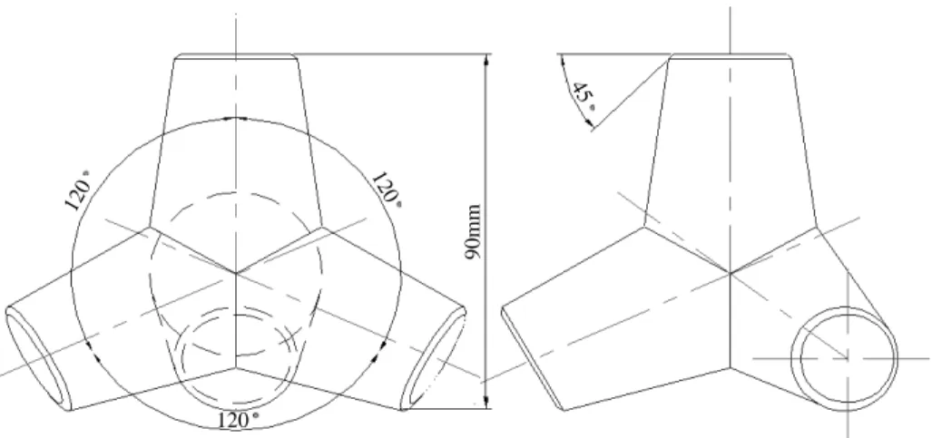
Fig. 1 .
100 μm PVC( 1.02) .
.
.
5
2mm .
,
.
Fastcam 1280pci, B&W .
500 (125 Frame/sec)
1280 1024
, 1/10
( 12 )
. 2
(CACTUS 3.1) .
(1)
.
C
fgf
i, g
i.
∑
n2i 1
(f
i ___f
i) (g
i ___g
i)
C
fg_____________________ (1)
∑
n2i 1
(f
i ___f
i)
2∑
n2i 1