A Study on Open BIM based Building Energy Evaluation based on Quantitative Factors
Inhan Kim*, Jin Jin** and Jungsik Choi***
ABSTRACT
Energy consumption by buildings accounts for a large part of the world’s energy consumption. Meth- ods to analyze building energy consumption before construction have been studied for decades. With BIM (Building Information Modeling) technology, architects can easily export building information to data models in order to analyze the design’s effect on building energy efficiency. Although several BIM-based energy simulation applications are currently available, utilizing these applications for energy efficiency simulation is difficult. In this paper, by comparing existing BIM-based energy applications, the authors test the building energy efficiencies estimated by some BIM models, offer ideas and solu- tions to problems that appeared during the test process and propose new methods for BIM-based energy evaluation based on quantitative factors.
Key words : BIM (Building Information Modeling), Energy Evaluation/Simulation, IFC (Industry Foundation Classes)
1. Introduction
The environmental impact of building construction and maintenance is enormous. In the United States, commercial and residential buildings account for a large proportion of total energy consumption and generate substantial construction and demolition waste
[1]. If building energy consumption were to be reduced, global energy consumption would drop.
Energy consumption in buildings is the result of a complex set of relationships between the external environment, the shape and character of the building components, equipment loads, lighting, mechanical system, building envelope, and air distribution strategies
[2]. Since these characteristics play a crucial role in determining a structure’s future energy consumption, design is central to energy performance.
Architects are largely responsible for the related environmental impact. Energy consumption charac- teristics are notoriously difficult and expensive to alter during the final stages of the design process,
which is when traditional energy simulation calculations take place. If architects could easily analyze their designs for energy efficiency during the early design phases, they would receive invaluable feedback that could be accounted for before the process was too far along to alter. To achieve this goal, architects require a digital model of the building they are designing, and a simulation tool that can determine its efficiency
[3].
BIM (Building Information Modeling)
†offers architects the opportunity to exchange building information data among different areas of the building lifecycle. With BIM technology, architects can easily export building information to data models (IFC, gbXML), then from data models to energy simulation applications in order to analyze designs for energy efficiency during the early design phases, compares different design proposals and offers feedback to improve the models (Fig. 1).
BIM technology is still in its initial stages. In this paper, through research on existing BIM-based energy applications, the authors provide an effective energy evaluation method to assess the energy
*Department of Architecture, Kyung-Hee University **Corresponding author, Department of Architecture, Kyung-Hee University/buildingSMART Korea
***BuildingSMART Korea - 논문투고일 : 2010. 03. 24 - 논문수정일 : 2010. 07. 14 - 심사완료일 : 2010. 07. 20
†
BIM is the process of generating and managing building data
during its life cycle. Typically it uses three-dimensional, real-
time, dynamic building modeling applications to increase pro-
ductivity in building design and construction
[4,9].
efficiency of some BIM models, offer ideas and solutions to problems that appeared during the evaluation process, and propose some new ideas based on BIM.
2. BIM and Energy Simulation
2.1 General Energy Simulation Method Energy simulation tools typically consist of a graphical user interface (GUI) and a thermal calculation engine. The simulation engine requires architects to provide inputs of the building geometry and layout, constructions, operating schedules, equipment loads (lighting, computers), heating, ventilating, and air- conditioning (HVAC) systems, local weather data, and utility rates (Fig. 2).
The thermal calculation engine is based on thermodynamic equations, principles, and assumptions that attempt to predict the actual thermal processes occurring in a building. The simulation engine uses input files of a defined format that contain a representation of the previously described input.
Based on this input, the engine performs a simulation
and writes its output into one or more output files.
2.2 Traditional Energy Simulation and BIM- Based Energy Simulation
For the traditional energy simulation process, an energy modeler uses information from drawings, photos, or other project data available on the proposed design to construct an energy model within an energy simulation program, which is simply an input process to an energy calculation engine. Misinterpretations of the input information are quite common. Furthermore, if the building design changes, the energy model must be revised directly, which currently requires manual duplication of the modification, which is very time consuming for architects and engineers.
Energy modeling using BIM has the potential to simplify the process described above by leveraging building information that exists in the architectural or mechanical models created by the project design team. This information may include geometric data, construction types and associated thermal properties, space loads and other useful simulation parameters.
Leveraging this data to eliminate duplicate construction of, or revisions to, the energy model can significantly reduce simulation time and improve the accuracy of the energy model
[6]. Meanwhile, by using BIM, the process of creating an energy model and preparing documentation becomes automated and formulaic; so architects can focus on the design process (Fig. 3).
3. Applications of BIM-Based Building Energy Simulation
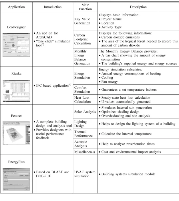
The following table (Table 1) is a comparison of some BIM-based building energy simulation applica- tions:
Fig. 1. Energy simulation process by BIM.
Fig. 2. General data flow of simulation engines[5]. (Edited based on the picture from “BIM lecture” of Graphisoft) Fig. 3. Time savings by the BIM-based energy simulation
workflow.
4. Applications to BIM Models for Energy Evaluation Tests
4.1 Four Models for the Test
Four models were constructed by the students from Kyung-hee University for the energy evaluation test. Model A and Model C are modeled in Graphisoft ArchiCAD while Model B and Model D are modeled in Autodesk Revit Architecture. Fig. 4 contains perspective views of these models.
Table 1. A comparison of some BIM-based building energy simulation applications
Application Introduction Main
Function Description
EcoDesigner
• An add on for ArchiCAD
• “One click” simulation tool
[7]Key Value Generation
Displays basic information:
• Project Name
• Location
• Activity Type Carbon
Footprint Calculation
Displays the following information:
• Carbon dioxide emissions
• The area of the tropical forest needed to absorb this amount of carbon dioxide
Monthly Energy Balance Generation
The Monthly Energy Balance provides:
• A bar chart showing the amount of energy consumption
• The building's supplied energy and energy sources Riuska
• IFC based application
[8]Energy Simulation
Energy simulation calculates:
• Annual energy consumptions of heating
• Cooling
• Fan energy Comfort
Simulation • Guarantees a set temperature indoors Heat Loss
Calculation • Steady-state heat loss calculation
• U-values automatically generated
Ecotect
• A complete building design and analysis tool
• Provides designers with useful performance feedback
Solar Analysis • Simulates internal sun penetration
• Optimizes shading design
• Overshadowing and site analysis Lighting
Design • Helps to design the lighting system of a building Thermal
Performance • Calculate the internal temperature Acoustic
Analysis • Help to analyze reverberation times Miscellaneous • Cost and environmental impact analysis EnergyPlus
• Based on BLAST and
DOE-2.1E HVAC system
simulation • Building systems simulation module
Fig. 4. IFC files show in Solibri Model Checker.
4.2 Rules and Criteria for the BIM Modeling Process
For the purpose of simplifying the simulation and comparison process as well as directly testing the models in energy simulation applications, the four models follow these rules:
(1) File format save:
After modeling in BIM applications, the four models are all saved as digital 3D building information models in open BIM standards/formats IFC
†2x3.
(2) Model composition:
Models only contain objects for walls, doors and windows, floor and roof slabs, and spaces/zones that illustrate the main functions of the building, according to the space program requirements.
(3) Complete envelope:
The sum of physical objects in the model (walls, slabs, doors, windows) contains the complete building envelope, i.e. no openings/voids to the outdoors (free-air) remain in the models. This criterion is important for energy assessment.
(4) External/Internal settings:
It is important to distinguish whether the objects are external or internal for the energy simulation, so the properties of the objects should be set in the
“property set” accurately, for example:
For the external walls, the value of property
“Pset_WallCommon|IsExternal” should be set as
“TRUE” to show that they are external walls (walls facing outdoor area) (Fig. 5).
The other objects (slab, door etc.) should be set similarly
[9,10].
For evaluation in BIM models, energy performance
needs to be well documented. For analyzing the energy consumption of the models, the authors applied EcoDesigner and Riuska to optimize BIM- based energy performance evaluations for the future.
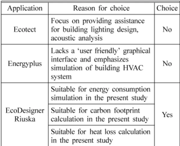
4.3 Reasons for BIM Tool Selections
Table 2 shows the reasons for selecting EcoDesigner and Riuska for the energy simulation test.
4.4 Processes and Results of BIM Tool Applications
4.4.1 Energy Consumption and Carbon Footprint Comparison in EcoDesigner
First, the authors opened the IFC models one by one in ArchiCAD and input the same information for each: Project Location: Seoul; Primary function:
Office.
The IFC files generated from ArchiCAD, EcoDesigner automatically recognizes key structural elements.
The application automatically calculates the areas, thickness and U-values for the building. However, in the IFC files generated from Revit, there are some problems when mapping the building envelopes (Fig.
6). For this issue the authors suggest two ways to go:
(1) Go back to Revit to assess their structure materials and assign them in EcoDesigner:
Revit contains a massive database of materials to choose from with thermal conductivity, density and heat capacities. If materials are not in the library, it is easy for architects to add their own custom materials.
Thicknesses and values can be edited as well (Fig. 7).
(2) Set all of the building envelopes to have the same properties and evaluate these models:
†
IFC (Industry Foundation Classes) is a task and schema spec- ification that provides standard ways to define information con- tained in BIM. IFC is an object-oriented data model developed by buildingSMART used to describe the relationships and prop- erties of building specific objects
[11].
Fig. 5. External/Internal setting in ArchiCAD.
Table 2. Reasons of BIM Tool Selections
Application Reason for choice Choice Ecotect Focus on providing assistance
for building lighting design,
acoustic analysis No
Energyplus Lacks a ‘user friendly’ graphical interface and emphasizes simulation of building HVAC system
No
EcoDesigner Riuska
Suitable for energy consumption
simulation in the present study
Suitable for carbon footprint Yes
calculation in the present study
Suitable for heat loss calculation
in the present study
We believe that it is more important for the simulation of the effects of building geometry and proposed shading solutions rather than detailed technical properties of the building elements.
Obviously, the first method is more time consuming than the second. We chose the second method for this reason. Since the MEP systems were not designed within these models, default settings were retained.
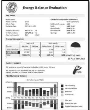
Fig. 8 shows the calculation results for model C.
Through this figure, architects can optimize the energy balance and see the total energy consumption and carbon footprint of the model.
Table 3 shows a comparison of energy consumption and carbon footprints for the four models.
Given the results generated from EcoDesigner, Model D is the most energy-efficient building of the four BIM models. Model D has the best energy consumption and carbon footprint among these four models.
4.4.2 Heat Loss Comparison in Riuska
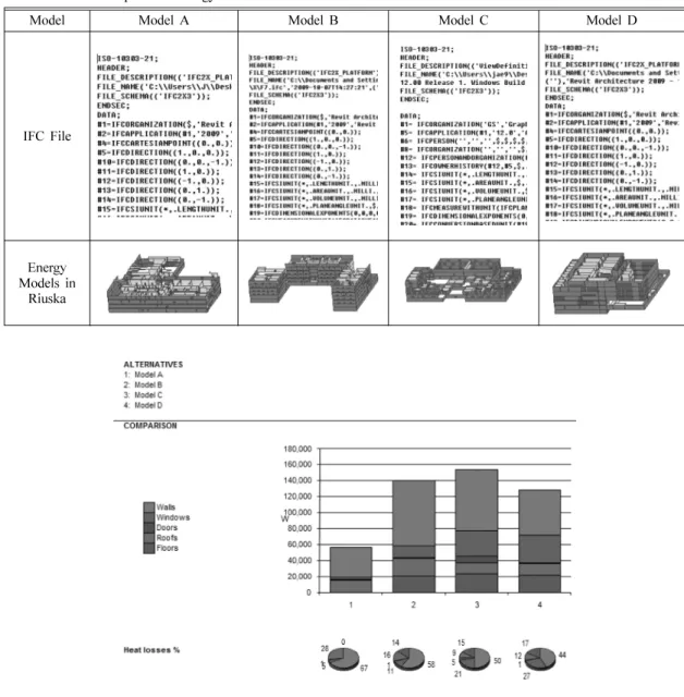
Table 4 shows the processing of IFC files imported into Riuska.
For these models, heat losses can be calculated and compared in Riuska. After creating a new project in Riuska, the four models are opened within the same
Fig. 7. Individual library generated in EcoDesigner.
Fig. 8. The calculation result for model C in EcoDesigner.
Table 3. Results of energy consumption and carbon footprint analyses
Model A Model B Model C Model D
Energy Consumption
(1 year) 119.06 KWh/m
2148.88 KWh/m
2117.15 KWh/m
288.81 KWh/m
2Carbon Footprint
(1 year) 1218 tons co2 1163 tons co2 1356 tons co2 976 tons co2
Fig. 6. Building envelope mapping problem.
project. Seoul is chosen as the project position and the weather data for Seoul is automatically loaded.
When the building envelopes mapping from IFC to Riuska, the similar mapping problems with EcoDesigner occurs, as the wall type properties have been set in ArchiCAD and Revit to distinguish external and internal walls, all of the external walls are automatically mapped into wall type “OW” 01 in Riuska library while all of the internal walls are automatically mapped into wall type “lW” 01.
To solve this problem, architects can modify the wall properties in the library to correspond to the
wall information. However, if the wall properties are set as various types, a large number of corresponding wall types should be created in the Riuska library.
For this analysis, a similar solution with EcoDesigner has been chosen. The default mapping in Riuska has been used and the generated results are as follows (Fig. 9):
From this graph, model A loses the least heat especially it almost did not lose heat by floors.
Furthermore, the walls account for the largest proportion of heat loss. Model C lost the most heat among these four models.
Table 4. IFC files imported to energy models in Riuska
Model Model A Model B Model C Model D
IFC File
Energy Models in
Riuska
Fig. 9. Heat loss comparison in Riuska.
5. Conclusion and Future Development
Currently BIM technology is still in its initial stages, deficiencies of current BIM technology are evident, however, undoubtedly BIM technology will be the definite trend in the architecture, engineering and construction industry in the future.
In this paper, the authors successfully model energy consumption, carbon footprint and heat losses using BIM-based applications. This effective energy simulation method compares models in building energy and carbon dioxide emission aspects with ease. EcoDesigner is based on the VIP-Energy calculation engine and Riuska is based on the DOE- 2.1E engine, since these famous engines have been tested by many cases, the test results are robust if the input data are correct. Architects can then modify and adjust the special combination and building envelope materials at the beginning stage of a project rather that at the end. Limitations in the current process of transferring information from BIM models to energy simulation should be noticed.
When do these kind of simulations, architects also need to keep in mind that most of these simulation tools are not intent as detailed analysis tools, more detailed dynamic simulation systems are needed for more precise simulation results.
In future work, the interoperability capabilities of various application tools should be improved. It is better to develop some APIs to combine the energy checking results with related green building standards, which makes the energy simulations more convenient to be used. Furthermore, if BIM-based applications became real-time simulation tools, they would be more convenient for architects.
Acknowledgements
This research was supported by a grant from the
High-Tech Urban Development Program funded by the Ministry of Land, Transport and Maritime Affairs.
References
1. US Department of Energy, Energy Efficiency and Renewable Energy Network (EREN). Geometric Design, Center if Excellence for Sustainable Devel- opment, 2003, Vol. 3, pp. 129-148, 1986.
2. GSA BIM Guide for Energy Performance Version 1.0, pp.9, February, 2009.
3. White Paper Energy analysis with ArchiCAD. http:
//www.graphisoft.com/products/archicad-solutions/
energize9_whitepaper.html.
4. Building Information Modeling. http://en.wikipe- dia.org/wiki/Building_Information_Modeling.
5. Tobias Maile, Martin Fischer & Vladimir Bazjanac.
Building Energy Performance Simulation Tools -a Life-Cycle and InteroperablePerspective. CIFE Working Paper #WP107, P24-25, December 2007.
6. GSA BIM Guide for Energy Performance Version 1.0, pp.12-13, February, 2009.
7. AEC MAGAZINE. http://aecmag.com/index.php?
option=com_content&task=view&id=303.
8. Granlund Software Help RIUSKA. http://bbs.topen- ergy.org/viewthread.php?tid=54219&extra=. pp.1.
9. Choi, J., Kim, I. and Jo, C., “Application Status of Domestic Architectural Industry of Open BIM and Development Direction”, Transactions of the Society of CAD/CAM Engineers , Vol. 14, No. 6, pp. 355- 363, 2009.
10. Open Planning and Design Competition for a New Museum Complex for Norway Nation Museum, 2009.
11. Industry Foundation Classes. http://www.iai-interna-
tional.org/Model/IFC(ifcXML)Specs.html.
김 인 한
1988
년 서울대학교건축학과졸업1991
년 미국Carnegie-Mellon
대학 건축학석사1994
년 영국Strathclyde
대학건축학1996
년박사~
현재 경희대학교 공과대학 건축학과교수2002
년~
현재한국CAD/CAM
학회이사2004
년~2008
년 사단법인STEP
센터 회장,
지식경제부2008
년~
현재 빌딩스마트협회 수석2010
년부회장~
현재대학건축학회이사 관심분야: BIM(Building Information
Modeling), CAAD,
데이터모델링 및 통합 전산설계환경(STEP, IFC),
건축정보기술, Digital Design Media
최 중 식
1999
년경희대학교건축공학과졸업2001
년경희대학교건축공학(
건축정보 기술)
석사2001
년~
현재 경희대학교 건축공학과2009
년박사과정~
현재빌딩스마트협회기술연구 소선임연구원관심분야
: BIM(Building Information
Modeling),
자동화 법규검토(Automated Code Checking),
CAAD,
데이터모델링및통합전산설계환경
(STEP, IFC),
건축정 보기술진 진
2008
년Henan institute of science and technology Landscape architecture Department
졸업2008
년~
현재 경희대학교 건축학과2010
년석사과정~
현재빌딩스마트협회기술연구 소연구원관심분야
![Fig. 2. General data flow of simulation engines [5] . (Edited based on the picture from “BIM lecture” of Graphisoft) Fig](https://thumb-ap.123doks.com/thumbv2/123dokinfo/5593977.487276/2.892.465.759.691.883/general-simulation-engines-edited-based-picture-lecture-graphisoft.webp)