Vol. 20, No. 1 pp. 1-8, 2019
Comparison Study of On-line Rotor Resistance Estimators based on Alternate QD Model and Classical QD Model for Induction Motor
Drives
Chun-Ki Kwon
1, Dong-Sik Kim
2*1Department of Medical IT Engineering,
2Department of Electrical Engineering, Soonchunhyang University
유도전동기 드라이브에서의 대안모델과 일반표준모델에 기반한온라인 회전자저항 추정기의 성능 비교 연구
권춘기1, 김동식2*
1순천향대학교 의료IT공학과, 2순천향대학교 전기공학과
Abstract Most of rotor resistance estimators utilizes Classical qd Model (CQDM) and Alternate qd Model (AQDM).
The rotor resistance estimators based on both models were shown to provide an accurate rotor resistance estimate under conditions where flux is constant such as a field-oriented control (FOC) based induction motor drives. Under the conditions where flux is varying such as a Maximum torque per amp (MTPA) control, AQDM based rotor resistance estimator estimates actual rotor resistance accurately even in different operating points. However, CQDM based rotor resistance estimator has not been investigated and its performance is questionable under condition where flux level is varying. Thus, in this work, the performance of CQDM based rotor resistance estimator was investigated and made comparisons with AQDM based estimator under conditions where flux level is significantly varying such as in MTPA control based induction motor drives. Unlike AQDM based estimator, the laboratory results show that the CQDM based estimator underestimates actual rotor resistance and exhibits an undesirable dip in the estimates in different operating points.
요 약 대부분의 회전자 저항 추정기는 표준모델(CQDM)과 대안모델(AQDM)을 활용한다. 두가지 모델에 기반한 회전자
저항 추정기들은 자속이 일정한 FOC와 같은 제어 환경에서는 정확한 회전자 저항 추정치를 제공하는 것으로 확인되었다.
반면, 단위전류당최대토크 (MTPA) 제어기와 같이 자속이 변화하는 동작환경에서는, AQDM에 기반한 회전자 저항 추정기가 다른 동작 운전점에서도 실제 회전자 저항을 정확하게 추정함을 보여주었다. 하지만, 자속이 변화하는 동작환경에서의
CQDM애 기반 회전자 저항 추정기의 성능은 검토된 적이 없으며 그의 성능은 의문이다. 따라서, 본 연구에서는 자속이 많이
변화하는 MTPA 제어기 기반 유도전동기 드라이브에서 CQDM에 기반한 회전자 저항 추정기의 성능을 검토하였으며
AQDM에 기반한 추정기와 비교하였다. AQDM에 기반한 추정기와는 달리, CQDM에 기반한 추정기는 실제 저항치보다 낮게
추정할 뿐만 아니라 여러 운전조건변화시마다 추정한 값에서 실제 존재할 수 없는 급격한 굴곡이 존재함을 실험 결과에서 확인하였다.
Keywords : Classical QD model, Alternate QD model, Rotor resistance estimator, Field-oriented control, Maximum torque per amp control
This work was supported in part by the National Research Foundation of Korea (NRF) grant funded by the Korea government (Ministry of Science and ICT) (no. 2017R1D1A1B03029844)
*Corresponding Author : Dong-Sik Kim(Soonchunhyang Univ.) Tel: +82-41-530-1370 email: [email protected]
Received November 20, 2018 Revised January 2, 2019 Accepted January 4, 2019 Published January 31, 2019
consideration of rotor resistance variation has been a significant issue in control design, particularly in the case of optimal controls[1-3].
Numerous rotor resistance estimators have been proposed in the literature. Most of these estimators are based on Classical qd induction motor model (CQDM)[4-6]. Another possible choice of an induction motor model in the design of a rotor resistance estimator is Alternate qd model (AQDM) which is recently proposed[7-8].
AQDM which has been shown to yield accurate predictions of motor behavior even under conditions where flux level is varying significantly such as Maximum Torque Per Amp (MTPA) control[8-10].
This is because AQDM simultaneously includes magnetic saturation and distribution system effects in rotor circuits unlike other models proposed in the literature.
Meanwhile, CQDM having constant parameters might provide reasonable performance where flux leve is constant under Field-Oriented Controlled (FOC) operation. However, under the conditions where flux level is varying such as MTPA controlled operation, the performance of CQDM is questionable because of its inherent deficiencies. Those deficiencies include failure to represent magnetic saturation and distribution system effects in rotor circuits. None of models but AQDM have been used in the design of a rotor resistance estimator for conditions under which magnetizing flux level varied significantly[7-8].
In this work, detailed comparisons of two rotor resistance estimators based on CQDM and AQDM are made under MTPA controlled operation where the magnetizing flux level is varying significantly. The experimental studies show that the rotor resistance estimator based on AQDM outperforms the estimator
2. Induction Motor Model
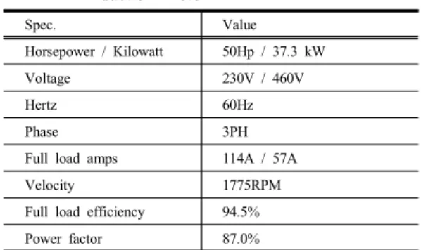
The test system for this work utilizes a 4-pole, 460V, 50Hp, 60Hz, delta-connected squirrel cage induction motor. Its detailed specifications is shown in Table 1.
Table 1. Specification of Baldor ZDM4115T-AM1 Induction Motor
Spec. Value
Horsepower / Kilowatt 50Hp / 37.3 kW
Voltage 230V / 460V
Hertz 60Hz
Phase 3PH
Full load amps 114A / 57A
Velocity 1775RPM
Full load efficiency 94.5%
Power factor 87.0%
2.1 Classcial QD Model
CQDM has been widely used in the analysis of induction motor thanks to its computational efficiency and convenience to use. The assumption of the model is so simple that magnetic saturation is neglected and rotor bar was treated as lumped system. This assumption might be appropriate near or at rated operating conditions. However, CQDM has been well known for its inaccuracy in power electronics based drives which have capability of operating induction motor in a variety of load[11].
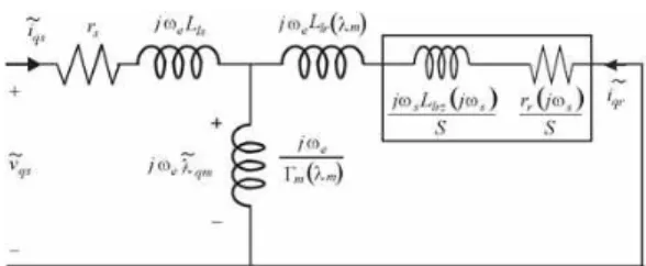
The steady-state equivalent circuit representing CQDM is shown in Fig. 1. Therein, leakage inductances in the stator and rotor are denoted as
and , the magnetizing inductance as , rotor resistance as . slip frequency, , is defined as
, and slip, , is defined as
.Fig. 1. Steady-state equivalent circuit of CQDM
The parameters of CQDM are treated to have constant values. Generally, and are assumed equal as well.
Using the methods set forth in [11], the parameters of CQDM for the test induction motor are listed in Table 2.
Table 2. Resultant parameters of CQDM for the test motor
Parameters
=
0.22Ω 4.16mH 91.5mH 0.159Ω
2.2 Alternate QD Model
Unlike CQDM, AQDM simultaneously addressed all the deficiencies that CQDM failed to represent. In addition, despite of good mathematical representation of induction motor, it is computationally efficient because it is non-iterative at each step. This model has been shown to yield quite accurate predictions of motor behavior in power electronics based drives[8-10].
The steady-state equivalent circuit representing AQDM in [10] is shown in Fig. 2. Therein, the rotor impedance,
, is separated into a real and imaginary part, which are denoted as and , respectively. Magnetizing flux linkage, , is equal to
. Observe that there is another part of rotor leakage inductance which is dependent on a frequency dependent linear portion because of skin effect in rotor bar circuits and inverter-machine interactions.Fig. 2. Steady-state equivalent circuit of AQDM
Since AQDM is designed to give maximum freedom to analysts, this work specified analytical forms of motor parameters as equations (1) - (4) for magnetic characteristics and distributed system effects in the rotor circuits. Therein, stator leakage inductance, , is treated as constant. However, rotor leakage inductance,
, and the absolute inverse magnetizing inductance,
areassumed function of magnetizing flux linkage. Rotor admittance,
, is function of slip frequency. These functional forms of equations (1) - (4) was found to give better fit to the measured impedance data taken from the test induction motor[9].The coefficients of each parameter are listed in Table 3.
(1)
∙
(2)
∙ (3)
(4)
3. Derivation of Rotor Resistance Estimator
Based on two induction motor models, CQDM and AQDM, on-line rotor resistance estimators are derived
(1) (2)
(3)
(4) 9.06e-4
1.40e-4 6.79e0 5.65e0
6,62e-1 3.21e-2
4.15e-3 5.03e0 4.40e-2
1.85e0 4.78e-4
7.35e-1
8.68e-1 3.17e-3
2.59e0
1.29e-1 8.76e-8
From stator measurements, the stator input impedance, , can be observed. By equating to the calculated value from the stator equivalent circuit, the stator impedance in looking into input terminal may be expressed as
(5) The superscript '' in is used to indicate a measured value. From (5), the impedance looking into the air-gap, , may be computed as
(6) Since in (6) has parallel circuit elements, it is conveniently expressed as an admittance
for CQDM (7-1)
for AQDM (7-2) where is the impedance of rotor side defined as
for CQDM (8-1)
for AQDM (8-2)
∙
(9)In (8)-(9), the superscript '^' in serves as a reminder that this is the estimated value; Similarly, will be the estimated magnitude of the magnetizing flux for AQDM based derivation. By the substitution of (6) into (7) and algebraic manipulation, , can be also expressed
for CQDM (10-1)
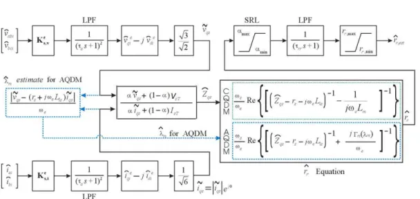
for AQDM (10-2) Fig. 3 depicts the block diagram of the rotor resistance estimator based on (9)-(10).
Therein, the stator input impedance, is readily obtained from the measured a- and b- phase inverter currents, and , and line-to-line inverter voltages,
and ,
(11)
These measured quantities are filtered by two cascaded first order low pass filters (LPF) to remove switching noise after transformation. In case of the possibility of division by zero and poor signal-to-noise ratio for low voltage condition due to noise or measurement error, equation (11) can be modified to
(12)
Fig. 3. Block diagram of rotor resistance estimators based on CQDM and AQDM
where
min
(13)In (13), and are defined as
i f
≥ (14)
and
i f
≥ (15),
respectively. Therein, and are a stator
voltage threshold and a stator current threshold which
are set to the level at which measurement deteriorates.
For practical use, the estimator also employed a slew rate limiter (SRL) to prevent transient behavior in an undesirable way, low-pass filter (LPF) to remove switching noise inherent in a drive. Finally, to keep the estimated value in reasonable range, the resulting estimated rotor resistance is bounded.
Another important part of the control for the rotor resistance estimator based on AQDM is the estimate of the flux level, which is needed because the absolute inverse magnetizing inductance, , in (10-2) is a function of . Once and are obtained, the estimate of peak amplitude of magnetizing flux linkage, , is readily calculated using
(16) Once the estimated flux level is determined, it may be used in conjunction with (9)-(10) to find the unconditioned rotor resistance estimate, .
4. Comparison of Rotor Resistance Estimators based on CQDM and
AQDM
The performances of two rotor resistance estimators were investigated and compared using laboratory experiment since the most significant validation step will be experimental.
For the purpose of experimental validation, an indirect approach must be used since it is difficult to directly measure the actual rotor resistance of the test induction motor. To investigate the accuracy of two rotor resistance estimators based on CQDM and AQDM, rotor resistance estimates are compared to the rotor resistance value used in design of MTPA control law at a certain temperature where two models were characterized.
To do this, consider MTPA control strategy whose control law may be expressed as
Fig. 4. Effect of temperature on torque with
=150(Nm) using the MTPA control strategy based on (17)-(18)
(17)
(18) using the procedure set forth in [9]. Therein, the test induction motor is driven at a speed of 900 rpm at a torque command of 150Nm.4.1 Comparison of rotor reistance estimates at the characterization temperature With this experimental setup, the electromagnetic torque was measured at each surface temperature of a point on the stator of the test induction motor at a particular operating condition. The resultant effect of temperature variation on torque is depicted in Fig. 4.
The time at which each data point was taken relative to the beginning of the study is designated +X where X is the time in minutes. The torque and the surface temperature of the test induction motor were measured every 5 minutes.
It is shown in Fig. 3 that the variation of the measured electromagnetic torque at the same operating condition is significant as stator temperature of the test induction motor rises.
As the stator surface temperature rises, the torque increase, reaches a maximum, and then decreases. The
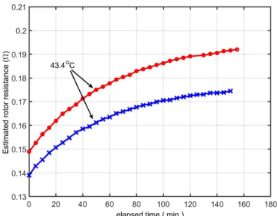
Fig. 5. Comparison of the estimated rotor resistance by two rotor resistance estimators at one operating condition with the torque command of 150Nm
desired torque was achieved at 43℃ at which temperature the test induction motor was characterized.
Except at the point when the stator surface temperature was 43℃, there is error in torque production. Note that at this temperature the effective rotor resistance calculated from in (10) with =1.79rad/s, is around 0.176Ω.
Now, it is stage to find rotor resistance estimates by the two rotor resistance estimators at the temperature of 43℃. With the same experimental setup, estimated values were measured and recorded by two rotor resistance estimators over a 2.5 hour period as shown in Fig. 5.
Therein, the estimate predicted by rotor resistance estimator based on AQDM at the temperature of around 43℃ is around 0.176Ω, which is very close to the one in the design of MTPA control strategy.
However, the estimate predicted by CQDM based one is around 0.160Ω. This tells us that AQDM based rotor resistance estimator provides highly accurate estimates while CQDM based rotor resistance estimator underestimates the actual rotor resistance.
4.2 Comparison of rotor resistance estimates over a variety of operating points A second study performed in order to see if the observations of the study in Fig. 5 would hold over a
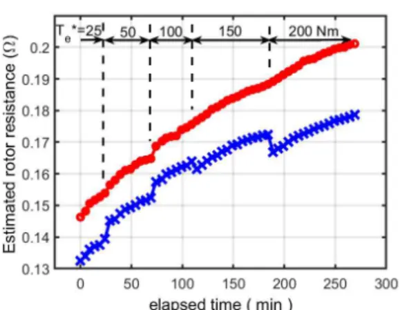
Fig. 6. Comparison of the estimated rotor resistance by two rotor resistance estimators at various operating conditions
variety of operating conditions. in the second study, the torque command was initially 25Nm , then stepped sequentially to 50Nm, 100Nm, 150Nm, and then finally 200Nm., thereby exercising the motor from very low to rated torque at a given speed(herein, 900rpm).
Since an MTPA control is used, each change in torque command also causes a change in magnetizing flux.
As in Fig. 5, it is also shown in Fig. 6 that the CQDM based estimator exhibits an undesirable dip in the rotor resistance estimate during each increase in torque command. This inaccurate estimate might cause poor performance of a control strategy when incorporated. This is because CQDM has the inherent deficiencies which failed to represent saturation in magnetic path and distribution system effects in rotor circuits. On the other hand, the proposed AQDM based rotor resistance estimator provides a much more continuous estimate in a reasonable way regardless of operating condition.
5. Conclusion
In this paper, the performance of CQDM based rotor resistance is investigated under conditions where the flux level is significantly varied such as in MTPA controlled drive. To this end, CQDM based rotor
resistance estimator was made comparison with AQDM based estimator which have shown excellent performance in MTPA controlled induction motor drives.
As shown in experimental results done in this work, CQDM based rotor resistance estimator underestimates the actual rotor resistance than AQDM based estimator.
To make it worse, it exhibits an undesirable dip in the rotor resistance estimate at the moment of change of operating points whereas AQDM based one does not.
These observations lead to a conclusion that the accuracy of a rotor resistance estimator is highly dependent upon which model and at what conditions to adopt. Herein CQDM is not recommended to be used in the design of rotor resistance estimator under operating condition where flux level is significantly varied.
References
[1] M. N. Uddin and Sang Woo Nam, "New Online Loss-Minimization-Based Control of an Induction Motor Drive," IEEE Transactions on Power Electronics, Vol.
23, pp. 926-933, March, 2008.
DOI: https://dx.doi.org/10.1109/TPEL.2007.915029 [2] Y. Wang, J. Arribas, T. Ito, and R. Lorenz, "Loss
Manipulation Capabilities of Deadbeat Direct Torque and Flux Control Induction Motor Drives," IEEE Transactions on Industry Applications, Vol. 51, No. 6, pp. 4454-4566, 2015.
DOI: https://dx.doi.org/10.1109/ECCE.2014.6954101 [3] S. Odhano, R. Bojoi, A. Boglietti, S. Rosu, and G. Griva,
"Maximum Efficiency per Torque Direct Flux Vector Control of Induction Motor Drives," IEEE Transactions on Industry Applications, Vol. 51, No. 6, pp. 4415-4424, 2015.
DOI: https://dx.doi.org/10.1109/TIA.2015.2448682 [4] M. Zaky and M. Metwaly, "Sensorless Torque/Speed
Control of Induction Motor Drives at Zero and Low Frequencies with Stator and Rotor Resistance Estimations," IEEE Journal of Emerging and Selected Topics in Power Electroncis, Vol. 4, No. 4, pp.
1416-1429, 2016.
DOI: https://dx.doi.org/10.1109/JESTPE.2016.2597003 [5] L. Zhao, J. Huang, H. Liu, B. Li, and W. Kong,
"Second-Order Sliding-Mode Observer With Online Parameter Identification for Sensorless Induction Motor Drives," IEEE Transactions on Industrial Electronics, Vol. 61, No. 10, pp. 5280-5289, 2014.
DOI: https://dx.doi.org/10.1109/TIE.2014.2301730
Conference, pp. 391-397, May 2005.
DOI: https://dx.doi.org/10.1109/IEMDC.2005.195752 [8] C. Kwon and S. D. Sudhoff, "An Adaptive Maximum
Torque per Amp Control Strategy," the 2005 International Electric Machines and Drives Conference, pp. 783-788, May 2005.
DOI: https://dx.doi.org/10.1109/IEMDC.2005.195811 [9] C. Kwon and S. D. Sudhoff, "Genetic Algorithm-based
Induction Machine Characterization Procedure with Application to Maximum Torque Per Amp Control,"
IEEE Transactions on Energy Conversion, Vol. 21, pp.
405-415, 2006.
DOI: https://dx.doi.org/10.1109/TEC.2006.874224 [10] S. D. Sudhoff, D. C. Aliprantis, B. T. Kuhn, and P. L.
Chapman, "An Induction Machine Model for Predicting Inverter-Machine Interaction," IEEE Transactions on Energy Conversion, Vol. 17, pp. 203-210, June 2002.
DOI: https://dx.doi.org/10.1109/TEC.2002.1009469 [11] P. C. Krause, O. Wasynczuk, S. D. Sudohff, and S.
Pekarek, Analysis of Electric Machinery and Drive Systems, p. 215-265, John Wiley & Sons, 2013.
DOI: https://dx.doi.org/10.1002/9781118524336
Chun-Ki Kwon [Regular member]
•Feb. 1994 : Korea Univ., Electrical Engineering, ME
•Aug. 2005 : Purdue Univ., Electrical Engineering, PhD
•Jun. 2006 ~ Feb. 2008 : Hyundai-Kia Motors Inc., Senior Research Engineer
•Mar. 2008 ~ current : Soonchunhyang Univ., Dept. of Medical IT Engineering, Associate Professor
<Research Interests>
Design of Induction Motor Design and Inverter Drives
Engineering, PhD
•Mar. 1992 ~ current : Soonchunhyang Univ., Dept. of Electrical Engineering Professor
<Research Interests>
Nonlinear control system, Digital Control System