• 검색 결과가 없습니다.

Hardware Implementation of HEVC CABAC Binary Arithmetic Encoder

N/A
N/A
Protected

Academic year: 2021

Share "Hardware Implementation of HEVC CABAC Binary Arithmetic Encoder"

Copied!
6
0
0

로드 중.... (전체 텍스트 보기)

전체 글

(1)

Hardware Implementation of HEVC CABAC Binary Arithmetic Encoder

Duyen Hai Pham * , Jeonhak Moon * , Doohwan Kim * , Seongsoo Lee *

Abstract

In this paper, hardware architecture of BAE (binary arithmetic encoder) was proposed for HEVC (high efficiency video coding) CABAC (context-based adaptive binary arithmetic coding) encoder. It can encode each bin in a single cycle. It consists of controller, regular encoding engine, bypass encoding engine, and termination engine. The proposed BAE was designed in Verilog HDL, and it was implemented in 180 nm technology. Its operating speed, gate count, and power consumption are 180 MHz, 3,690 gates, and 2.88 mW, respectively.

Key words: HEVC, CABAC, binary arithmetic encoder, hardware, implementation

* School of Electronic Engineering, Soongsil University, sslee@ssu.ac.kr, 010-9182-3835

★ Corresponding author

※ Acknowledgment

“This research was supported by the System IC Commercialization R&BD Program (10049498, "4K UHD HEVC/VP9 SoC for Streaming Smart Device") funded by the Ministry of Trade, industry &

Energy."

Manuscript received Dec. 15, 2014; revised Dec. 29, 2014; accepted Dec. 29. 2014

I. Introduction

HEVC (high-efficiency video coding) [1]-[7] is the newest video coding standard and the successor to H.264/AVC (advanced video coding). When compared to H.264/AVC, HEVC shows higher compression ratio with more complex hardware implementation.

HEVC uses CABAC (context-based adaptive binary arithmetic coding) for encoding syntax element and generating bitstream. It is an entropy coding with high coding efficiency. As shown in Fig. 1, CABAC encoder consists of four main blocks: binarizer, context modeler, BAE (binary arithmetic encoder), and bitstream generator [5].

First, binarizer converts non-binary-valued syntax elements into binary symbols (called as bins).

Second, context modeler calculates and updates the

probability of each bin. Third, BAE converts bins into bits based on the probability from context modeler. Finally, bitstream generator combines output bits of BAE into bitstream.

In this paper, hardware architecture of BAE was proposed for HEVC CABAC encoder. It was designed in Verilog HDL as an independent module that can be integrated into HEVC CABAC encoder.

It was simulated, verified, and implemented in 180nm technology.

II. HEVC CABAC Binary Arithmetic Encoding

HEVC CABAC BAE is an entropy encoding with lossless data compression. It overcomes some limitations of Huffman coding such as non-integer length and probability distribution change.

It uses a certain interval, and probability of each bin narrows down the interval. Therefore the outcome gets fewer bits than the original bins. BAE has two variables to represent the interval: ivlLow and ivlRange. There are three encoding processes in BAE: regular encoding, bypass encoding, and termination. They are described in the Figs. 2-4.

Regular encoding is applied to the symbols with

changing distribution. In the regular encoding

process, BAE gets context model from context

(2)

190 j.inst.Korean.electr.electron.eng.Vol.18,No.4,630∼635,December 2014

Fig. 1. Block diagram of HEVC CABAC encoder. (Modified from [5])

Fig. 2. Regular encoding process. (Modified from [1],[8])

Fig. 3. Bypass encoding process. (Modified from [1],[8])

Fig. 4. Termination process. (Modified from [1],[8]) modeler after context model is updated. Bypass

encoding is applied to the symbols with equal distribution, i.e. its appearance frequency is unchanged. Termination is applied to the symbols indicating the end of encoding. Unlike regular encoding, bypass encoding and termination do not need context modeling.

III. Hardware Architecture

1. Top Architecture

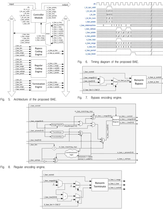
The proposed BAE consists of four modules such as controller module, regular encoding engine, bypass encoding engine, and termination engine, as shown in Fig. 5.

The controller is connected to binarizer and

(3)

Fig. 5. Architecture of the proposed BAE.

Fig. 6. Timing diagram of the proposed BAE.

Fig. 7. Bypass encoding engine.

Fig. 8. Regular encoding engine.

Fig. 9. Termination engine.

(4)

192 j.inst.Korean.electr.electron.eng.Vol.18,No.4,630∼635,December 2014

Sequence Class A Class B Class C Class D

Size 2560x

1600 1920x 1080 832x

480 416x 240

Frame Rate 30 24 50 50

Frames 10 10 10 10

Bit Depth 8 8 8 8

Encoder 3 Configurations (low delay, random access, and all intra)

Technology 180 nm

Operating Frequency 180 MHz Gate Counts 3,960 gates Critical Path Delay 5.2 ns Dynamic Power 2.88 mW Leakage Power 1.55 uW Table 1. Test sequences.

Table 2. Synthesis Results.

context modeler to get bin string and context modelling information of each bin. It determines the encoding mode of each bin and assign it to the corresponding encoding engine. It assigns ivlLow and ivlRange to regular encoding engine, bypass encoding engine, and termination engine. Updated output variables are sent to output port via multiplexer and they are stored in the buffer to encode next bin. Fig. 6 shows the timing chart of BAE.

2. Bypass Encoding Engine

The bypass coding engine gets four input variables (ivlLow, ivlRange, binVal, outstanding count) from the controller. ivlLow is updated in the renormalization phase for bypass bin. The bypass encoding engine is designed as shown in Fig. 7.

3. Regular Encoding Engine

The regular encoding engine gets six input variables (ivlLow, ivlRange, binVal, outstanding count, pstate, valMps) from the controller.

ivlLpsRange is derived from the lookup table of RangeTabLPS. TransIdxMps and TransIdxLps are defined in the lookup tables of [1]. Update condition of pstate and valmps is as follows.

if (binVal == valMps)

pStateIdx = transIdxMps(pStateIdx);

else {

if(pStateIdx == 0) valMps = 1 - valMps

pStateIdx = transIdxLps(pStateIdx) }

ivlRange and ivlLow are updated in the renormalization phase for regular bin. The regular encoding engine is designed as shown in Fig. 8.

4. Termination Engine

The termination engine gets four input variables (ivlLow, ivlRange, binVal, outstanding count) from the controller. ivlRange and ivlLow are updated in the renormalization phase. The termination engine is

designed as shown in Fig. 9.

5. Renormalization

Renormalization in the software [2] can take some cycles. In hardware implementation, this can be reorganized to operate in one cycle by using the number of zero leading detection (ZLD) in ivlRange variable. Implementation of ZLD is described in [5].

IV. Experiments and Results The proposed BAE was designed in Verilog HDL.

4 standard test sequences (class A, B, C, and D) with 3 encoder configurations (low delay, random access, and all intra) were generated from HEVC HM-11 reference software [2], as shown in Table 1.

These 12 test vectors were used in the front-end simulation with Verilog HDL, and the designed BAE was passed in all tests.

The designed BAE was implemented in 180 nm technology. CAD tool was supported by IC Design Education Center (IDEC). As shown in Table 2, the operating speed, gate count, and power consumption of the back-end design are 180 MHz, 3,960 gates, and 2.88 mW, respectively. Its critical path delay is 5.2 ns. It can encode one bin in a single cycle.

V. Conclusions

(5)

In this paper, a binary arithmetic encoder for HEVC CABAC encoder was proposed. It was designed in Verilog HDL with 4 modules to cover 3 processing modes. It was implemented in 180 nm technology. It can encode one bin per cycle. Its operating speed, gate count, and power consumption are 180 MHz, 3,960 gates, and 2.88 mW, respectively.

References

[1] B. Bross, W. Han, J. Ohm, G. Sullivan, and T.

Wiegand, “JCTVC-L1003_v34: High efficiency video coding (HEVC) text specification draft 10,” Joint Collaborative Team on Video Coding (JCT-VC), Jan. 2013.

[2] HEVC software repository HM-11 reference model at https://hevc.hhi.fraunhofer.de/svn/svn_

HEVCSoftware/branches/HM-11.0-dev/

[3] S. Han, W. Nam, and S. Lee, “Design of Low-Area HEVC Core Transform Architecture”, Journal of IKEEE, vol. 17, no. 2, pp. 119-128, Jun.

2013.

[4] J. Lee and S. Lee, “8×8 HEVC Inverse Core Transform Architecture Using Multiplier Reuse”, Journal of IKEEE, vol. 17, no. 4, pp. 570-578, Dec.

2013.

[5] D. Pham, J. Moom, and S. Lee, “Hardware Implementation of HEVC CABAC Binarizer”, Journal of IKEEE, vol. 18, no. 3, pp. 356-361, Sep. 2014.

[6] M. Wien, “High Efficiency Video Coding”, Springer, 2014.

[7] D. Shim and H. Cho, “Understanding of HEVC Standard Technology”, Hongrung Publishing Co., 2014.

[8] Y. Kim, J. Moon, W. Choi, and S. Lee, “Design of High Performance Arithmetic Encoder for CABAC in H.264/AVC”, Proceedings of Internationa Conference on Microelectronics, Nanoelectronics, and Optoelectronics, pp. 103-106, 2009.

BIOGRAPHY

Duyen Hai Pham (Student Member) 2007 : BS degree in Physics, Soongsil University.

2013~Now : MS candidate in Electronic Engineering, Soongsil University.

<Main Interest> HEVC, Multimedia SoC Design

Jeonhak Moon (Student Member)

2005 : BS degree in Electronic Engineering, Soongsil University.

2008 : MS degree in Electronic Engineering, Soongsil University.

2008~Now : PhD candidate in Electronic Engineering, Soongsil University.

<Main Interest> HEVC, Multimedia SoC Design

Doohwan Kim (Student Member)

2015 : BS degree in Electronic Engineering, Soongsil University.

2015~Now : MS candidate in Electronic Engineering, Soongsil University.

<Main Interest> HEVC, Multimedia

SoC Design

(6)

194 j.inst.Korean.electr.electron.eng.Vol.18,No.4,630∼635,December 2014

Seongsoo Lee(Life Member)

1991 : BS degree in Electronic Engineering, Seoul National University.

1993 : MS degree in Electronic Engineering, Seoul National University.

1998 : PhD degree in Electrical Engineering, Seoul National University.

1998~2000 : Research Associate, University of Tokyo 2000~2002 : Research Professor, Ewha Womans University

2002~Now : Associate Professor in School of Electronic Engineering, Soongsil University

<Main Interest> HEVC, Low-Power SoC Design,

Multimedia SoC Design, Battery Management

수치

Fig. 1. Block diagram of HEVC CABAC encoder. (Modified from [5])
Fig. 5. Architecture of the proposed BAE.

참조

관련 문서

Phase Equilibria and Cage Occupancy of Binary Hydrates : Its Application to Gas Hydrate Refrigeration

§ Null-path-length balancing: comparing the null-path-length of each of the two sub-trees (the length to the closest null sub- tree/empty node). § Weight balancing:

aSystem design performs many design tasks at different levels of abstraction.. `Requirements, Specifications, Architecture, Coding,

Electron probe micro-analyzer image of Zr-4%Si binary alloys; (a).. X-ray diffraction profiles of as-cast Zr-xSi binary alloys, which shows the dual phases.. Magnetic

 Kernel 1, which has an arithmetic intensity of 0.5 FLOPs/byte, is limited by memory bandwidth to no more than 8 GFLOPS/sec.  Kernel 2, which has an arithmetic intensity of

[From Binary Alloy Phase Diagrams, 2nd edition, Vol. Reprinted by permission of ASM International, Materials Park, OH.].. 11.23, Callister &amp; Rethwisch 9e.. [From Binary

[From Binary Alloy Phase Diagrams, 2nd edition, Vol. Reprinted by permission of ASM International, Materials Park, OH.].. 11.23, Callister &amp; Rethwisch 9e.. [From Binary

Q: Why don’t we just use a prime number as our base N since it’s so easy to find the decryptor