1. 서 론
농수원으로 사용되는 물을 효과적으로 관리하 기 위해 농촌지역에 담수보가 설치되어 있으며 담수보의 수위 조절용으로 전도 수문이 주로 사 용된다. 전도 수문의 개폐장치로서는 유압식과 로프식이 있는데 여기서는 전도수문의 개폐작동 을 위한 5 종류의 유압회로에 대해서 작동 특성 과 에너지 효율에 대하여 분석하였다 특히. AC 전원이 미치지 못하는 지역에서의 수문 작동은 부득이 소형엔진이나 배터리에 의해 이루어져야 하므로 효율적인 수문 작동이 중요하다.
전도수문용 유압장치 2.
는 전도수문용 유압장치의 종류의
Fig.1~Fig.5 5
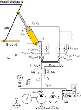
유압회로도를 나타낸다. Fig.1에 나타난 유압회로 는 유압공급장치, 1개의 편로드실린더, 3위치 4유 로 방향제어밸브 실린더 헤드측에, 1개의 파일럿 작동 첵밸브, 1개의 미터인(meter-in) 유량제어밸 브 실린더 로드측에, 1개의 파일럿작동 첵밸브, 1 개의 미터인(meter-in) 유량제어밸브로 구성되어 있으며 통상적으로 많이 사용된다.
에 나타난 유압회로
Fig.2 (1)는 유압공급장치, 1개 의 편로드실린더, 3위치 4유로 방향제어밸브 실, 린더 헤드측에 1개의 파일럿작동 첵밸브, 1개의 미터인(meter-in) 유량제어밸브, 1개의 미터아웃 유량제어밸브로 구성되어 있다 실린
(meter-out) .
더 로드측에는 배관이 되어 있지 않으므로 항상
전도 수문용 유압장치의 에너지 효율에 관한 연구
이 성래†
Study for the Energy Efficiency of Hydraulic System of Turnover-Type Sluice Gate
Seong-Rae Lee†
Key Words: Energy-Efficiency(에너지 효율), Hydraulic System(유압장치), Turnover-Type(전도식), Sluice Gate(수문)
Abstract
The turnover-type sluice gate is typically actuated by the hydrauic system. The hydraulic system may be a open circuit type or a closed circuit type. The open circuit type hydraulic system is composed of a uni-directional pump, a directional control valve, pilot operated check valves, flow control valves, single-rod cylinders. The closed circuit type hydraulic system is composed of a bi-directional pump, pilot operated check valves, check valves, a counter balance valve, single-rod cylinders. The energy efficiencies of two hydraulic systems for the turnover-type sluice gate are compared here.
회원 건양대학교 기계공학과,
†
E-mail : [email protected] TEL : 041-730-5191
FAX : 041-736-4079
대기압을 유지한다고 볼 수 있으며 수문의 상승 은 유압에 의해 강제적으로 이루어지지만 수문의 하강은 수문 자중과 담수보에 갇힌 물의 압력에 의해 이루어진다.
에 나타난 유압회로는 유압공급장치 개
Fig.3 , 1
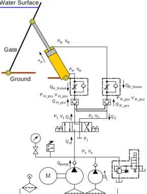
의 편로드실린더, 3위치 4유로 방향제어밸브 실, 린더 헤드측에 1개의 파일럿작동 첵밸브, 1개의 미터아웃(meter-out) 유량제어밸브 실린더 로드측, 에 1개의 파일럿작동 첵밸브, 1개의 미터아웃
유량제어밸브로 구성되어 있다
(meter-out) . Fig.1
에 나타난 유압회로와 유사하지만 유량제어에서 미터인 방식 대신에 미터아웃 방식을 적용하였 다.
에 나타난 유압회로는 유압공급장치 개
Fig.4 , 1
의 편로드실린더, 3위치 4유로 방향제어밸브 실, 린더 헤드측에 1개의 카운터밸런스밸브로 구성되 어 있다 파일럿작동 첵밸브를 적용하는 대신에. 급속한 자중하강을 방지하기 위해 카운터밸런스 밸브를 적용하였다.
에 나타난 유압회로는 와는 달
Fig.5 Fig.1~Fig.4
리 폐회로형 유압장치로서 방향제어밸브를 사용 하지 않으며 펌프의 회전방향에 의해서 수문의 상승 및 하강 방향이 결정된다.(2,3) 실린더 헤드측 에 1개의 카운터밸런스밸브(4), 작동유 탱크측과 펌프하단측 사이에 1개의 파일럿작동 첵밸브(4), 1 개의 첵밸브(4)가 설치되어 있고 작동유 탱크측과 펌프상단측 사이에 1개의 파일럿작동 첵밸브, 1 개의 첵밸브가 설치되어 있다 급속한 자중하강. 을 방지하기 위해 카운터밸런스밸브를 적용하였 으며 또한 유사시 자중하강을 대비하여 실린더 헤드측과 작동유 탱크 사이에 유량제어밸브를 설 치하였다.
전도수문용 유압장치의 컴퓨터 3.
시뮬레이션
에 나타난 전도수문용 유압장치의 Fig.1~Fig.5
작동 특성 및 에너지 효율 특성을 파악하기 위해 컴퓨터 시뮬레이션을 실시하였다. 시뮬레이션에 적용된 공통적인 시스템 상수값은 Table 1에 나 타나 있으며 시뮬레이션 언어는 MATLAB(5), 적 분알고리즘은 ode45, 최대적분시간간격은 0.01초, 데이터획득시간간격은 0.1초로 설정하였다.
M Gate
Water Surface
Ground
QH_fcvin
QH_pcv
PsVs Qs
Qpump Pt Q1
P1V1 P2V2 Q2 PHVH
PRVR
QR_fcvin
QR_pcv xp
PH_pcvVH_pcv
PR_pcvVR_pcv
Fig. 1 Open circuit hydraulic system 1 of the turnover-type sluice gate
M Gate
Water Surface
Ground
PHVH
PsVs Qpump
Qs Q1
Qfcvout
Qpcv Q2 Qfcvin
P2V2 P1V1
PpcvVpcv PfcvVfcv
Pt xp
Fig. 2 Open circuit hydraulic system 2 of the turnover-type sluice gate
M Gate
Water Surface
Ground
QH_fcvout
QH_pcv
PsVs Qs
Qpump Pt Q1
P1V1 P2V2 Q2 PHVH
PRVR
QR_fcvout
QR_pcv xp
PH_pcvVH_pcv
PR_pcvVR_pcv
Fig. 3 Open circuit hydraulic system 3 of the turnover-type sluice gate
M Gate
Water Surface
Ground
Qpump PsVs Qs Pt Q1
P1V1 P2V2 Q2 PRVR
PHVH
Qcbv xp
Fig. 4 Open circuit hydraulic system 4 of the turnover-type sluice gate
Oil Tank
xp
Qpump
Qcbv
Qpcva Qpcvb
Qcva
Qcvb DC Motor
Hand Wheel Gate
Water Surface
Ground
pumpbelow V
pumpbelow P PR
VR
PH VH
Fig. 5 Closed circuit hydraulic system of the turnover-type sluice gate
Table 1. Common system parmeters
Symbols Values
piston diameter, 0.1 m rod diameter, 0.055 m gate mass, 1250 kg set pressure of counter balance
valve, _ 1.0 MPa cracking pressure of check valve,
_
0.035 MPa cracking pressure of pilot operated
check valve, _ 0.21 MPa tank pressure, 0.1 MPa pump handle radius, 0.3 m pipe volume of head side, 0.001 pipe volume of rod side, 0.001 All other control volumes except
cylinder 0.001
bulk modulus of oil, 588 MPa pump diplacement, 100 cc/rev pump rpm, _ 120rpm pump flow, 200 cc/s
에 나타난 전도수문용 유압장치에 Fig.1~Fig.5
적용된 각종 유압밸브의 유량계수값은 각각
에 나타나 있으며 컴퓨터 시뮬레 Table 2~Table 6
이션 결과는 각각 Fig.6~Fig.10에 나타나 있다 실. 린더 로드 끝단에 가해지는 부하는 수문의 각도
도 도 에 따라 변하지만 변화 범위는
(0 ~60 )
12400N~13000N 이다.
에 나타난 유압장치의 경우 시뮬레이션 결 Fig.1
과는 Fig.6에 나타나 있으며 수문의 상승 시에는 유압공급장치의 공급압력 실린더 헤드측 및 로, 드측 압력은 각각 3.13MPa, 1.96MPa, 0.50MPa이 며 작동유가 펌프로부터 받은 유압동력은 606W 이다 수문의 하강시에는 유압공급장치의 공급압. 력, 실린더 헤드측 및 로드측 압력은 각각 이며 작동유가 펌프로 2.40MPa, 1.66MPa, 0.06MPa
부터 받은 유압동력은 460W이다.
에 나타난 유압장치의 경우 시뮬레이션 결 Fig.2
과는 Fig.7에 나타나 있으며 수문의 상승 시에는 유압공급장치의 공급압력 실린더 헤드측 및 로, 드측 압력은 각각 2.80MPa, 1.69MPa, 0.10MPa이 며 작동유가 펌프로부터 받은 유압동력은 540W 이다 수문의 하강시에는 유압공급장치의 공급압. 력, 실린더 헤드측 및 로드측 압력은 각각 이며 작동유가 펌프로 2.80MPa, 1.62MPa, 0.10MPa
부터 받은 유압동력은 200W이다 수문 하강시에. 는 단지 파일럿압력만이 필요하므로 유압공급장 치의 릴리프밸브 조정압력을 1MPa로 낮추었다.
에 나타난 유압장치의 경우 파일럿압력이 Fig.3
작아서 파일럿작동 첵밸브를 완전히 열지 못하여 파일럿작동 첵밸브의 작동 및 정지가 반복된다.
이에따라 시뮬레이션 시간이 너무 오래 걸려서 시뮬레이션 결과는 얻지 못하였으며 정상상태 해 석 결과 수문의 상승 시에는 유압공급장치의 공 급압력 실린더 헤드측 및 로드측 압력은 각각, 이며 작동유가 펌프로 3.09MPa, 2.37MPa, 1.08MPa
부터 받은 유압동력은 599W이다 수문의 하강시. 에는 유압공급장치의 공급압력, 실린더 헤드측 및 로드측 압력은 각각 1.04MPa, 1.84MPa, 이며 작동유가 펌프로부터 받은 유압동력 0.32MPa
은 188W이다.
에 나타난 유압장치의 경우 시뮬레이션 결 Fig.4
과는 Fig.8에 나타나 있으며 수문의 상승 시에는 유압공급장치의 공급압력 실린더 헤드측 및 로, 드측 압력은 각각 2.27MPa, 1.82MPa, 0.29MPa이 며 작동유가 펌프로부터 받은 유압동력은 434W 이다 수문의 하강시에는 유압공급장치의 공급압. 력, 실린더 헤드측 및 로드측 압력은 각각 이며 작동유가 펌프로 3.17MPa, 3.55MPa, 2.78MPa
부터 받은 유압동력은 614W이다.
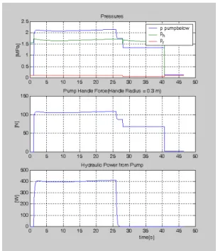
에 나타난 유압장치의 경우 시뮬레이션 결 Fig.5
과는 Fig.9에 나타나 있으며 수문의 상승 시에는 펌프하단 압력 실린더 헤드측 및 로드측 압력은,
각각 2.10MPa, 1.67MPa, 0.10MPa이며 작동유가 펌프로부터 받은 유압동력은 401W이다 수문의. 하강시에는 펌프하단 압력 실린더 헤드측 및 로, 드측 압력은 각각 0.11MPa, 3.48MPa, 2.74MPa이 며 작동유가 펌프로부터 받은 유압동력은 526W 이다 수문 하강시 펌프회전을 정지시킨 채 실린. 더 헤드측에 연결된 유량제어밸브에 의해 자중하 강을 시키면 시뮬레이션 결과는 Fig.10과 같으며 수문의 하강시에는 펌프하단 압력 실린더 헤드, 측 및 로드측 압력은 각각 1.34MPa, 1.63MPa, 이며 작동유가 펌프로부터 받은 유압동력 0.06MPa
은 0W이다.
Table 2. Flow coefficients of valves in Fig.1
Symbols Values
directional control valve:
, , , , , ×
pilot operated check valve:
_,_ ×
restrictor(head side):_ ×
restrictor(rod side): _ ×
restrictor check valve:_ ×
Table 3. Flow coefficients of valves in Fig.2
Symbols Values
directional control valve:
, , , , , ×
pilot operated check valve:
_,_ ×
restrictor(head side): _ ×
restrictor check valve:_ ×
Table 4. Flow coefficients of valves in Fig.3
Symbols Values
directional control valve:
, , , , , ×
pilot operated check valve:
_,_
×
restrictor(head side): _ ×
restrictor(rod side): _ ×
restrictor check valve: _ ×
Table 5. Flow coefficients of valves in Fig.4
Symbols Values
directional control valve:
, , , , , ×
counter balance valve- sequence valve: _
×
counter balance valve-check
valve: _ ×
Table 6. Flow coefficients of valves in Fig.5
Symbols Values
counter balance valve-sequence valve:
_
×
counter balance valve-check
valve: _ ×
pilot operated check valve:
_,_
×
check valve: ×
restrictor: _ ×
Fig. 6 Simulation results of hydraulic circuit in Fig.
1 (1)pressures: supply pressure, head pressure, rod ptessure (2)pump handle force (3)hydraulic power from pump
Fig. 7 Simulation results of hydraulic circuit in Fig.
2 (1)pressures: supply pressure, head pressure, rod ptessure (2)pump handle force (3)hydraulic power from pump
Fig. 8 Simulation results of hydraulic circuit in Fig.
4 (1)pressures: supply pressure, head pressure, rod ptessure (2)pump handle force (3)hydraulic power from pump
Fig. 9 Simulation results of hydraulic circuit in Fig.
5(forced up, forced down) (1)pressures: pump below pressure, head pressure, rod ptessure (2)pump handle force (3)hydraulic power from pump
Fig. 10 Simulation results of hydraulic circuit in Fig. 5(forced up, free down) (1)pressures: pump below pressure, head pressure, rod ptessure (2)pump handle force (3)hydraulic power from pump
4. 결론
전원이 미치지 못하는 지역에서의 수문 작 AC
동은 배터리나 소형엔진에 의해 이루어져야 하므 로 에너지 효율적인 수문 작동이 중요하다 수문. 의 개폐작동 중에 실린더 로드 끝단에 작용하는 부하력이 12400N~13000N 인 경우 전도수문의 개 폐작동을 위한 5 종류의 유압회로에 대해서 작동
특성과 에너지 효율에 대하여 분석하였다.
에 나타난 유압회로에서 유압펌프에 Fig.1~Fig.5
의해 작동유에 가해지는 유압동력은 수문 상승시 에는 401W~606W, 하강시에는 0W~614W이었다. 수문 상승시에는 밸브에서의 압력손실을 최소화 시키는 것이 중요하며 수문 하강시에는 가능한 수압과 수문자중에 의한 자유하강을 시키는 것이 필요하다. 부득이 강제하강이 필요한 경우에는 밸브에서의 압력손실을 최소화시키되 실린더 로 드측에서 진공압이 발생하는 것을 방지해야 하며 또한 파일럿작동 첵밸브가 적절히 작동할 수 있 도록 해야 한다.
참고문헌
(1) Lee, J. K., Kim, T. S., Kim, T. H., 1995, About Hydraulics: Circuits and Materials, Mechatronics Research, pp. 148.
(2) Daehan Engineering, 2006, Hydraulic-type floodgate winch, Korea Patent No. 10-0559454.
(3) Lee, S. R., 2006, "Study for the Actuation of Turning-Type Sluice Gate by the Bi-Directional Pump and Single-Rod Cylinders," Proceedings of the KSME 2006 Fall Annual Meeting, pp.674~679.
(4) 2001, Power Control Hydraulic Equipment Catalogue, Tokimec Co., pp.F15~F16, F3-F7, C45-C52.
(5) Hanselman, D. and Littlefield, B., 1997, The Student Edition of MATLAB, Prentice Hall.