이 논문의 일부내용은 FGCN2011에 발표되었음.
*정회원, 중원대학교 컴퓨터시스템공학과
접수일자 : 2012년 9월 27일, 수정완료 : 2012년 11월 24일 게재확정일자 : 2012년 12월 14일
Received: 27 September 2012 / Revised: 24 November 2012 / Accepted: 14 December 2012
*Corresponding Author: [email protected]
Dept. of Computer System Engineering, Jungwon University, Korea
http://dx.doi.org/10.7236/JIWIT.2012.12.6.111
JIWIT 2012-6-14
차량통신시스템에서의 멀티홉 전송 방법
A multi-hop Communication Scheme in Vehicular Communication Systems
조 웅
*Woong Cho
요 약 차량통신은 정보통신기술과 차량 및 도로 기술을 결합한 대표적인 융합기술중 하나이다
.
일반적으로 차량통 신은WAVE (Wireless Access in Vehicular Environments)
라 일컫어지는IEEE 802.11p
표준을 채택하고 있다.
본 논문에 서는 차량-
노변기지국간 통신 및 차량간 통신을 지원하는IEEE 802.11p
기반 통신시스템의 멀티홉 전송방식에 대해 알 아본다.
먼저IEEE 802.11p
기반 통신시스템의 성능에 대해 간단히 살펴본 후 브로드캐스팅과 유니캐스팅의 멀티홉 전 송 방식에 대해 소개한다.
제안된 방식의 성능은 실제 시스템을 구현한 후 실험을 통한 결과를 통해 알아본다.
Abstract Vehicular communication is one of main convergence technologies which combines information and communication technology (ICT) with vehicle and road industries. In general, vehicular communication adopts IEEE 802.11p standard which is commonly referred as wireless access in vehicular environments (WAVE). In this paper, we investigate a multi-hop communication scheme for IEEE 802.11p based communication systems which support both vehicle-to-infrastructure (V2I) and vehicle-to-vehicle (V2V) communications. First, we briefly overview the performance of IEEE 802.11p based communication systems. Then, a multi-hop communication scheme is introduced for both broadcast and unicast. The performance of proposed scheme is presented via experimental measurements.
Key Words : Vehicular communication, WAVE, multi-hop communication, broadcast, unicast
Ⅰ. Introduction
Vehicular communications have been considered as one of the attractive research areas by applying communication technologies to the road. To apply vehicular communication technologies with one common type, the standards for vehicular communications have been developed in several
institutions such as IEEE, ETSI and ISO. Among them
IEEE 802.11p and IEEE 1609.X, which are commonly
referred as wireless access in vehicular environments
(WAVE), are widely accepted as a common standard
for vehicular communications. IEEE 802.11p specifies
MAC/PHY layer standard in 5.9GHz frequency band by
modifying IEEE 802.11 a/b/g
[1]. To characterize the
wireless channels in vehicular communications,
practical data are collected in various vehicular environments
[2]. Throughput and frame error rate of IEEE 802.11a/b/g based system are investigated in
[3]and IEEE 802.11p based prototype is introduced in
[4]. In the form of vehicle-to-vehicle (V2V) or vehicle-to-infrastructure (V2I) communications, vehicular communications provide numerous applications such as traffic information service, anti-collision warning, accident alarming, internet service, multimedia downloading, and etc, where the former is widely used for intelligent transport system (ITS)/Telematics services by adopting bidirectional communications, and the later is mainly used for safety services by using multi-hop communications. Among various applications, the most promising one is the public safety
[5]. Vehicular communications and multi-chop communications have been studied in the existing literature with various approaches
[6, 7, 8]. To adopt multi-hop scheme in vehicular communications, the characteristics of multi-hop communication in vehicular networks are investigated in
[9]. With location and delay information, a V2I multi-hop protocol for enhancing the performance of MAC and routing layers is introduced in
[10, 11], and the reliability analysis for broadcast service in vehicular networks is carried out in
[12]. However, almost of existing work mainly deals with theoretical approaches and simulations.
Furthermore, a multi-hop protocol with IEEE 802.11p standard is not thoroughly investigated.
In this paper, we first briefly review the IEEE 802.11p based communication system and its performance. Then, a vehicle multi-hop protocol (VMP) including practical measurement results is introduced.
The rest of this paper is organized as follows. The review of communication system is introduced in Section II. In Section III, we present the proposed VMP, and performance measurement results are introduced in Section IV. The concluding remarks are given in Section V.
II. Reviews of IEEE 802.11p based communication systems
In general, vehicular communication systems consist of antenna, on-board-unit (OBU) vehiclar terminal, road-side-equipment (RSE), and ITS center/server.
Both OBU and RSE have the communication module which is equipped with Modem, MAC and RF module.
The OBU provides both V2V and V2I communications, and multi-hop communication is supported. Our system is designed to support the IEEE 802.11p based system, where the system works 5.9GHz frequency band (5.835~5.925GHz) with 10MHz bandwidth, and modulation supports OFDM (BPSK, QPSK, 16QAM) with carrier sense multiple access/ collision avoidance (CSMA/CA) and enhanced distributed channel access (EDCA) MAC protocol. With these system specifications, the following basic requirements are satisfied:
․Communication methods: Broadcast, unicast
․Communication range: Up to 1km
․Latency: Less than 100 msec
․Mobility: Up to 200km/h
With the above mentioned system, we measured the performance of system using QPSK with 5.85GHz center frequency where we consider various packet sizes and vehicle speeds for both V2I and V2V communications. For detailed measurement setup and results, we refer the reader to
[7]. The basic performance can be summarized as followings:
․Communication range: approximately 1 km
․Packet error rate: Less than 5% for broadcast, less than 0.15% for unicast
․Link setup time: Approximately 1msec
․Latency: Less than 10msec (various depending on the packet size)
III. Vehicle multi-hop communications
Most safety-related applications in vehicular
communications use broadcast method to disseminate safety related information to all surrounding vehicles.
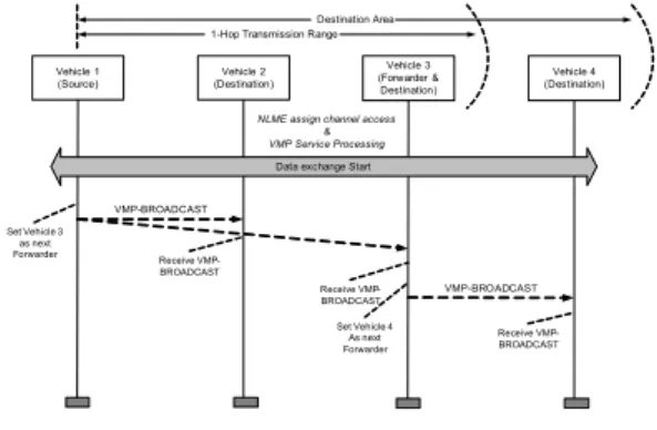
VMP provides an efficient broadcast/unicast schemes for fast dissemination of safety message within the critical area. The core of the VMP is to specify multiple reliable forwarders with differentiated forwarding delay and exploit cooperative forwarding mechanism when forwarders fail to transmit the messages. In this paper, the VMP provides a position-based routing scheme for delivering message from source to the fixed site or moving vehicle besides miles away with quality assurance. It utilizes the geographic location of the destination instead of using the network address. Fig.1 depicts VMP scenarios in vehicular communications where (a) and (b) represent VMP-BROADCAST and VMP-UNICAST, respectively. VMP-BROADCAST is used for delivering messages in specific area, and VMP-UNICAST is used for transmitting message to the designated node (vehicle). In VMP-BROADCAST, the forwarder is chosen from several nodes within the communication range, whereas the forwarder of VMP-UNICAST is predetermined before the messaged is transmitted. The detailed scheme is discussed in the following section.
(a)
(b)
그림 1. 차량통신에서의 VMP (a) VMP-BROADCAST (b) VMP-UNICAST
Fig 1. VMP in vehicular communications (a) VMP-BROADCAST (b) VMP-UNICAST
1. VMP-BROADCAST
VMP-BROADCAST is used for broadcasting the
data to all nodes in the specific area. If the designated nodes are located within the communication range, the source node simply transmits data by broadcasting.
Otherwise, the data is transmitted by using multi-hop communication of the forward nodes (forwarder) where the forwarder is predetermined by the source node. The destination node of VMP-BROADCAST is based on the location not identification number. Therefore, all nodes located in the designated area are regarded as the target nodes and receives the data. The nodes check the location information using the header information. Depending on the location information, each node set the node as the target node or deletes the received information.
Vehicle 1
(Source) Vehicle 2
(Destination)
VMP-BROADCAST
Vehicle 3 (Forwarder &
Destination)
Vehicle 4 (Destination)
VMP-BROADCAST Data exchange Start
NLME assign channel access
&
VMP Service Processing
Set Vehicle 3 as next
Forwarder Receive VMP-
BROADCAST
Receive VMP- BROADCAST
Receive VMP- BROADCAST 1-Hop Transmission Range
Destination Area
Set Vehicle 4 As next Forwarder
그림 2. VMP-BROADCAST의 데이터 흐름 Fig 2. Data flow of VMP-BROADCAST
Fig. 2 represents the data flow of VMP- BROADCAST. Before transmitting VMP-BROADCAST message, each node, i.e., a vehicle, broadcasts “hello”
message to all nodes. The “hello” message is
transmitted every 100msec. Then, each vehicle knows
the location, moving direction and speed of neighbor
nodes using “hello” message. The source node can
predetermine the destination as the designated area or
the number of hop. In Fig. 2, the vehicle 1 broadcasts
the data to the designated area. Since the vehicle 1 has
the information of neighbor vehicles, vehicle 1 can
select the forwarder for multi-hop communication; the
vehicle 3 is selected as the forwarder in Fig. 2. When
the vehicle 1 broadcasts the data, both the vehicle 2 and
3 receive the data, and the vehicle 2 deletes the received data, whereas the vehicle 3 forwards the received data. The vehicle 3 can also decide the next target nodes. In our example, the vehicle 4 is the destination node, and vehicle 3 broadcasts the data to the vehicle 4.
Vehicle 1 (Source)
Vehicle 2 (Forwarder )
VMP-LREQ
Vehicle 3 (Forwarder )
Vehicle 4 (Destination)
VMP-LREQ Data exchange Start
NLME assign channel access
&
VMP Service Processing
Start Search Destination Address
Receive VMP-
LREQ Receive VMP-
LREQ
Receive VMP- LREQ 1-Hop Transmission Range
Distance for searching Destination
VMP-LREP VMP-LREP
Set Vehicle 2 As next Forwarder Set Vehicle 1
As Destination Receive VMP-
LREP VMP-UNICAST
VMP-UNICAST Set Vehicle 3
as next Forwarder
Receive VMP- UNICAST Set Vehicle 4
As Destination VMP-
UNICAST
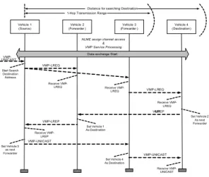
그림 3. VMP-UNICAST의 데이터 흐름 Fig 3. Data flow of VMP-UNICAST
2. VMP-UNICAST
VMP-UNICAST is used for transmitting the data where the geographical information of specific node is determined. The data flow of VMP-UNICAST is depicted in Fig. 3. When the target node is the one-hop neighbor node, the source transmits the data to the target node directly by unicast. When the location of target nodes is undetermined, first the VMP-location request (VMP-LREQ) message is flooded to all networks by broadcast to detect the current location of the specific node. Notice that the information of neighbor nodes is already known to the source node by using “hello” message as the same as the case of broadcast. When VMP-location reply (VMP-LREP) is received, the location of target node is determined.
Then, the closest node between the neighbor node and the target node is regarded as the forwarder. Finally, the data is transmitted to the target node by the multi-hop unicast of forwarders.
IV. Experimental measurements
In this section, we represent experimental measurement results of VMP. The performance of VMP is measured with respect to packet delivery ratio, end-to-end delay, and throughput. Due to the long communication range, it is hard to establish the measuring environment for broadcast. Therefore, our measurement is carried out only using unicast.
그림 4. 멀티홉 성능측정을 위한 셋업
Fig 4. Setup for multi-hop communications
1. Measurement setup
Fig. 4 represents measurement setup for multi-hop communication. We use 5 OBUs and measure the performance up to 4 hops. To measure the performance, 5 OBUs are located sequentially, and each OBU is set up to know only the information of adjacent OBU(s).
Then, the source node generates and transmits the data using Smart bit instrument Notice that although we use OBU for measurement, OBU can replace with RSE.
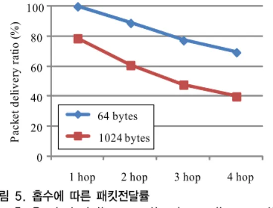
2. Measurement results (1) Packet delivery ratio
For packet delivery ratio, the length of 64 bytes and
1024 bytes frame is used with 16 QAM signal. For each
length, 100000 frames are transmitted. Fig. 5 represents
the measurement results of packet delivery ratio
depending on the number of hop. The results show that
the packet delivery ratio decreases as the number of
hop increases and the packet length is long. This is due
to the increment of collisions between the nodes, and
the probability of collision increases as the packet
length increases. Although the more results of packet
delivery ratio are not presented, it is measured that the packet delivery ratio is 100% for both 64 and 1024 bytes when the number of transmitted frame is 100 and 1000, which indicates that small amount of data traffic cannot induce packet loss.
Packet delivery ratio (%)
0 20 40 60 80 100
1 hop 2 hop 3 hop 4 hop 64 bytes
1024 bytes
그림 5. 홉수에 따른 패킷전달률
Fig 5. Packet delivery ratio depending on the number of hops
0 10 20 30 40 50 60 70
1 hop 2 hop 3 hop 4 hop 64 bytes
1024 bytes
End-to-End delay (msec)
그림 6. 홉수에 따른 지연
Fig 6. End-to-end delay depending on the number of hops
0 1 2 3 4 5
1 hop 2 hop 3 hop 4 hop
Throughput (Mbps)
그림 7. 홉수에 따른 전송률
Fig 7. Throughput depending on the number of hops