• 검색 결과가 없습니다.

Surface hardness measurement of NiP-plated AA7050

N/A
N/A
Protected

Academic year: 2021

Share "Surface hardness measurement of NiP-plated AA7050"

Copied!
7
0
0

로드 중.... (전체 텍스트 보기)

전체 글

(1)

<연구논문>

한국표면공학회지

J. Korean Inst. Surf. Eng

ISSN 1225-8024(Print) Vol.54, No.4, 2021.

ISSN 2288-8403(Online)

1. Introduction

Aluminum 7050 alloy is a heat treatable alloy which has high toughness, high strength and high stress corrosion cracking resistance. It is commonly used for aeronautical structural components, extrusion parts and stamp forgings. However, its relatively low hardness together with high friction coefficient limits their further applications for tribological purpose in mechanical parts.

To improve the hardness and tribological performance of aluminum alloys, their surfaces need to be coated with hard anodizing films, plasma electrolytic oxidation coatings or hard metals.

Anodized aluminum alloys showed increased hardness by decreasing electrolyte temperature [1, 2]. Hardness of anodic oxide films was increased by sealing treatments of the anodic oxide film in Ni-acetate solution, boiling water and NaAlO

2

solution [3]. Polytetrafluoroethylene (PTFE) and anodic aluminum oxide (AAO) composite film was fabricated by depositing PTFE particles into porous anodic aluminum oxide film using electrophoretic deposition (EPD) process [4]. Self-lubricating

Surface hardness measurement of NiP-plated AA7050

Sungmo Moon

1,2,*

, Juseok Kim

1,3

2

Advanced Materials Engineering, Korea University of Science and Technology, Daejeon 34113, Republic of Korea

3

Department of Materials Science and Engineering, Pusan National University, Busan 46241, Republic of Korea

(Received 27 July, 2021 ; revised 20 August, 2021 ; accepted 25 August, 2021)

Abstract

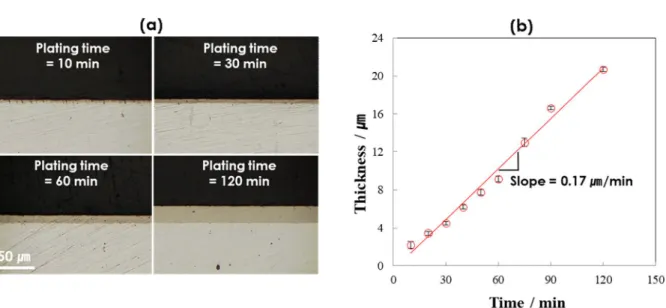
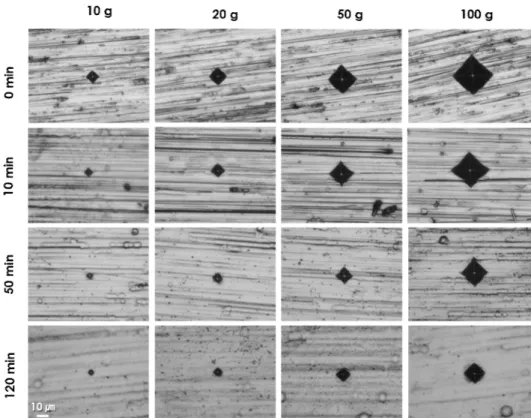
This paper is concerned with the surface hardness measurement of NiP-coated AA7050 using different loads from 10 to 100 g. The surface hardness was observed to increase from 180 to 600 H
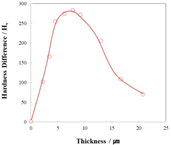
v

with increasing NiP layer thickness, depending on the load applied for indentation. When NiP coating thickness is thinner than 2 ㎛, the surface hardness of NiP-coated AA7050 was mainly determined by AA7050 substrate, while it was significantly increased by NiP coating layer when NiP coating thickness is thicker than 2 ㎛. Hardness of AA7050 substrate itself was not dependent on the applied load but the hardness of NiP-coated AA7050 was largely influenced by the load applied for indentation. The largest difference of hardness between 10 g and 100g of applied loads, was obtained at the NiP thickness of about 8 ㎛ above which the measured hardness at 10 g reached a maximum value of about 600 H

v

. It was also observed that indentation-induced plastic deformation next to the indented zone occurs when NiP layer is 5.64 times thicker than the depth of impression formed by indentation.

Keywords : Surface hardness, NiP, AA7050

*Corresponding Author: : Sungmo Moon Tel: +82-55-280-3549; Fax: +82-55-280-3570 E-mail∶ [email protected]

Surface Materials Division, Korea Institute of Materials Science, Gyeongnam 51508, Republic of Korea

1

Surface Materials Division, Korea Institute of Materials Science,

https://doi.org/10.5695/JKISE.2021.54.4.171

(2)

polytetrafluoroethylene-containing PEO (PEO-PTFE) composite coatings were prepared by vacuum impregnation on plasma electrolytic oxidized Al2024 alloy [5]. Improved tribological response of AA 2024 was achieved by DLC/NiP duplex coating [6]. Laser surface alloying of an A356 aluminum alloy using nickel and Ni–Ti–C powders improved its tribological behavior by providing a reinforcement of Al–Ni or Al–Si-Ti intermetallics and TiC particles [7].

Micro-Vickers hardness of aluminum alloys coated with anodic oxides was measured readily from the anodic oxide surface using an ink-impregnation method [8, 9]. Hardness of anodic oxide films is known to depend on the flaws and imperfections like vacant spaces within them [1, 9]. Measurement of micro-Vickers hardness was performed on NiP deposited on EN8 steel substrate at applied load of 500 g [10]. Hardness of electroless NiP deposited on aluminum alloys could be influenced not only by substrate but also by the load applied for hardness measurement if the NiP coating thickness is not thick enough. At present, the effects of NiP coating thickness on the hardness measured from the NiP coating surface on an aluminum alloy has not been fully understood.

In this paper, the effects of NiP coating thickness and applied load for micro-Vickers hardness measurement on the NiP coating surface on AA7050 were investigated and plastic deformation behavior of NiP layer and substrate was discussed in view of the ratio of NiP layer thickness to depth of impression formed by indentation.

2. Experimental

Al7050 alloy disc samples (wt.%, Cu 2.3, Mg 2.3, Zn 6.2, Zr 0.12, Fe and Si < 0.1 and Al balance) with diameter of 25mm and thickness of 2 mm, were abraded by SiC papers successively up

to # 2000 SiC paper, washed with tap water, dried with an air stream and then used for experiments. The disc samples were first immersed in a commercial zincating solution for 2 min at RT. The first zincate-treated samples are etched in nitric acid solution and then immersed again in the same zincating solution for 2 min to form a zincate layer of good adhesion. The double zincate-treated samples were immersed to form NiP layers in a commercial electroless NiP plating solution for various durations up to 120 min at 80 ℃.

The zincating pre-treatment is employed to improve the adhesion of the NiP layer prepared by electroless plating method. Thickness of the Ni-P layer was obtained from the cross-sectional observation using SEM (Scanning Electron Microscopy, JSM-6610LV). Micro-Vickers hardness was measured on the NiP layer surface using micro-Vickers hardness tester (V-test II, Bareiss) with a pyramidal-diamond indenter at four different loads of 10, 20, 50 and 100 g. The hardness was measured at five points on each specimen and their average value was obtained. The impressions remaining after indentation were observed using optical microscope (3D digital microscope, HiROX) and SEM.

3. Results and discussion

Cross-sections of NiP-coated AA7050 and their thicknesses are presented in Fig. 1 as a function of NiP electroplating time. The NiP layer was formed uniformly over the entire surface of AA7050 by electroless plating after double zincate treatment. The NiP coating layer thickness increased linearly with plating time at a growth rate of about 0.17 ㎛/min.

Micro-Vickers hardness of NiP-coated

AA7050 was measured from the NiP surface

and the surface hardness values are plotted

against electroless plating time and NiP

172 Sungmo Moon et al./J. Korean Inst. Surf. Eng. 54 (2021) 171-177

(3)

thickness in Fig. 2(a) and 2(b), respectively.

Hardness of the NiP-coated AA7050 surface increased with increasing NiP plating time and NiP thickness, suggesting improved surface hardness of AA7050 by NiP coating.

The surface hardness of NiP-coated AA7050 was determined mainly by AA7050 substrate, if NiP coating thickness is thinner than 2

㎛. On the other hand, the surface hardness is largely influenced by NiP layer if NiP coating thickness is thicker than 2 ㎛. It is interesting to note that the surface hardness of NiP-coated AA7050 reaches a maximum value of about 600 H

v

, if NiP coating layer thickness is thicker than a critical value of

about 8 ㎛.

In Fig. 2(b), it should be pointed out that the hardness of NiP-coated AA7050 depends on not only the NiP coating thickness but also the load applied for indentation. Figure 3 shows changes in the surface hardness of NiP-coated AA7050 with the applied load for indentation. It is apparent that hardness of AA7050 substrate itself does not depend on the applied load but the hardness of NiP-coated AA7050 is significantly decreased with increasing applied load for indentation.

In order to understand why the surface hardness of NiP-coated AA7050 decreases with the applied load for indentation, it is Fig. 1. (a) Cross-sections and (b) thickness of Ni-P layer formed on AA7050 with electroless plating time

Fig. 2. Hardness of NiP-plated Al7050 alloy with (a) electroless plating time and (b) NiP layer thickness. The

hardness was measured at four different loads of 10, 20, 50 and 100 g.

(4)

necessary to assume that not only NiP layer but also AA7050 alloy substrate are deformed when it is indented from the NiP layer surface. Since more plastic deformation occurs by applying higher load for indentation, AA7050 substrate could contribute more significantly to the measured hardness with increasing the load for indentation. This could explain the reduced hardness of NiP-coated AA7050 with applied load in Fig. 3.

The magnitude of decreased surface hardness on NiP-coated AA7050 samples by changing the applied load from 10 g to 100g, is plotted against NiP layer thickness in Fig. 4. The largest reduction of hardness between 10 g and 100g of applied loads was obtained at the NiP thickness of about 8 ㎛ above which the measured hardness at 10 g reached a steady-state value of about 600 H

v

. This suggests that the largest difference of hardness between 10 g and 100g of applied loads is obtained when most of plastic deformation by indentation using 10 g of load occurs within the NiP layer and the impression at 100 g of load is formed by plastic deformation of not only NiP layer but also AA7050 substrate.

In general, more than 600 H

v

of surface hardness of NiP-plated AA7050 is required

for practical use in contact with sliding balls for an intermediate shaft in cars. To use AA7050 for the intermediate shaft, its surface should become hard enough not to be indented by sliding balls. Assuming that the surface hardness of about 600 H

v

at the load of 100 g is sufficient for use with sliding balls in the intermediate shaft, it can be said that NiP layer should be thicker than 20 ㎛. The minimum thickness of NiP layer not to be indented by the sliding balls in an intermediate shaft is to be examined further.

Fig. 3. Hardness of NiP-plated Al7050 alloy with applied load for indentation.

Fig. 4. Hardness difference of NiP-plated Al7050 alloy between the highest and lowest values measured at different loads in Fig. 3.

174 Sungmo Moon et al./J. Korean Inst. Surf. Eng. 54 (2021) 171-177

(5)

Size of the indentation formed by pyramidal indenter increased with increasing load and it decreased with increasing NiP plating time, as exhibited in Fig. 5. The reduced indentation size with NiP plating time reveals that the surface of NiP-plated AA7050 becomes more resistive against an external force as the NiP layer thickness increases.

The shapes of indentation impressions formed by pyramidal indenter are examined in more detail by SEM and the results are displayed in Fig.

6. The indented surfaces of AA7050 substrate without NiP coating and 3.5 ㎛ thick NiP-coated specimen showed a dark single cross line at the center of the impression but 9.6 and 21.3 ㎛ thick NiP-coated surfaces exhibited bright double bands along with a dark cross line at the center of the impression. Another interesting observation is the formation of indentation-induced plastic deformation next to the indented zone, as indicated by arrows in Fig. 6(d). On the other hand, the indentation-induced plastic deformation next to the indented zone was not observed when the NiP layer thickness of 9.6 ㎛ is 1.83 times thicker than 5.23 ㎛ of the depth of impression, as observed in Fig. 6(c).

By considering the angle of 136° of a pyramidal indenter used for micro-Vickers hardness measurement, depth of impression (h) formed by the indenter can be calculated using Eq. (1)

h = (D/2) x tan 22° (1) where D is the average size of impression diagonals.

Table 1 displays h and l/h for different NiP

layer thicknesses from 0 to 21.3 ㎛. Depth of

impression formed on the 21.3 ㎛thick NiP-coated

AA7050 surface at 100 g of load (Fig. 6(d)) was

calculated to be about 3.77 ㎛. Considering that

the NiP layer thickness is 5.64 times thicker than

the depth of impression, it can be said that

plastic deformation of the 21.3 ㎛thick NiP-coated

AA7050 occurs only within the NiP coating layer

during indentation at 100g of load. This may

explain why the indentation-induced plastic

deformation next to the indented zone occurs

only when the NiP coating thickness is much

thicker than the depth of impression formed by a

pyramidal indenter in Fig. 6(d). Further study on

Fig. 5. Optical microscope images of Al7050 alloy plated with Ni-P for different durations from 0 to 120 min

after indentation at various applied loads from 10 to 100 g.

(6)

the relationship between indentation-induced plastic deformation and thickness of NiP layer is necessary.

There were observed black spots on the NiP-coated AA70705 surface. The number of the black spots decreased while their size increased with increasing NiP coating thickness. The black spots seem to be formed by corrosion through pinhole defects within the NiP coating layer.

4. Conclusions

Hardness of NiP-coated AA7050 was measured from the NiP coating surface using different loads from 10 to 100 g and it was analyzed as a function of the NiP layer

thickness and applied load for indentation.

The following results are obtained in this work.

1. The surface hardness of AA7050 was significantly improved from 180 to 600 H

v

by coating with NiP layer.

2. The surface hardness of NiP-coated AA7050 was mainly determined by AA7050 substrate when NiP coating thickness is thinner than 2 ㎛. On the other hand, the surface hardness is largely influenced by NiP layer when NiP coating thickness is thicker than 2 ㎛.

3. Hardness of AA7050 substrate itself does not depend on the applied load but the hardness of NiP-coated AA7050 is significantly decreased with increasing applied load for indentation.

4. The largest difference of between 10 g Fig. 6. SEM images of indented regions of Al7050 alloy with NiP coating thickness of (a) 0, (b) 3.5, (c) 9.6 and (d) 21.3 ㎛. The indentation was conducted at an applied load of 100 g.

NiP layer thickness,

l [㎛] 0 3.5 9.6 21.3

Average size of impression

diagonals, D [㎛] 33.04 33.04 25.91 18.70

Depth of impression,

h [㎛] 6.67 6.67 5.23 3.78

l/h ratio - 0.52 1.83 5.64

Table. 1. NiP layer thickness (l), average size of impression diagonals (D), depth of impression (h) and ratio of l/h on AA7050. The applied load for indentation was 100 g.

176 Sungmo Moon et al./J. Korean Inst. Surf. Eng. 54 (2021) 171-177

(7)

and 100g of applied loads was obtained at the NiP thickness of about 8 ㎛ when the measured hardness at 10 g reached a maximum value of about 600 H

v

. The largest difference of hardness between 10 g and 100g of applied loads is explained by the facts that most of plastic deformation at 10 g of load occurs within the NiP layer while large portion of plastic deformation occurs within AA7050 substrate at 100 g of load.

5. Indentation-induced plastic deformation next to the indented zone was observed only when NiP layer is thick enough more than 5 times comparing with depth of impression formed by indenter.

Acknowledgment

This research was financially supported by Korea Institute of Materials Science (PNK7930) and by the Technology development Program of the Ministry of SMEs and Startups (S2838879).

References

[1] Jieqin Lu, Guoying Wei, Yundan Yu, Changfa Guo, Li Jiang, Aluminum alloy AA2024 anodized from the mixed acid system with enhanced mechanical properties, Surfaces and Interfaces 13 (2018) 46-50.

[2] T. Aerts, Th. Dimogerontakis, I. De Graeve, J. Fransaer, H. Terryn, Influence of the anodizing temperature on the porosity and the mechanical properties of the porous anodic oxide film, Surface

& Coatings Technology 201 (2007) 7310–

7317.

[3] Moonsu Kim, Hyeonseok Yoo, Jinsub Choi, Non-nickel-based sealing of anodic porous aluminum oxide in

NaAlO

2

, Surface & Coatings Technology 310 (2017) 106-112.

[4] Dongya Zhang, Guangneng Dong, Yinjuan Chen, Qunfeng Zeng, Electrophoretic deposition of PTFE particles on porous anodicaluminum oxide film and its tribological properties, Applied Surface Science 290 (2014)466-474.

[5] Cheng Lu, Xiaochun Feng, Jingjing Yang, Junhong Jia, Gewen Yi, Erqing Xie, Yuan Sun, Influence of surface microstructure on tribological properties of PEO-PTFEcoating formed on aluminum alloy, Surface and Coatings Technology 364 (2019) 127-134.

[6] M. H. Staia, E. S. Puchi Cabreram A. Iost, A. Zairi, S. Belayer, A. Van Gorp, Tribological response of AA 2024-T3 aluminium alloy coated with aDLC duplex coating, Tribology International 85 (2015) 74.

[7] C. D’Amato, J. Buhagiar, J. C. Betts, Tribological characteristics of an A356 aluminium alloy laser surfacealloyed with nickel and Ni–Ti–C, Applied Surface Science 313 (2014) 720-729.

[8] Sungmo Moon, Novel Methods for Measuring the Surface Hardness of Anodic Oxide Films on Aluminum Alloy.

J. of Korean Inst. Surf. Eng. 53 (2020) 36-42.

[9] Sungmo Moon and Jong-joo Rha, Surface Hardness Measurement of Anodic Oxide

Films on AA2024 based an

Ink-Impregnation Method, J. of Korean Inst. Surf. Eng. 53 (2020) 80-86.

[10] I. Saravanan, A. Elayaperumal, A.

Devaraju, M. Karthikeyan, A. Raji, Wear

behaviour of electroless Ni-P and

Ni-P-TiO2composite coatings on En8

steel, Materials Today: Proceedings 22

(2020) 1135-1139.

수치

Fig.  2.  Hardness  of  NiP-plated  Al7050  alloy  with  (a)  electroless  plating  time  and  (b)  NiP  layer  thickness
Fig.  4.  Hardness  difference  of  NiP-plated  Al7050  alloy  between  the  highest  and  lowest  values  measured  at  different  loads  in  Fig
Table  1  displays  h  and  l/h  for  different  NiP  layer  thicknesses  from  0  to  21.3  ㎛

참조

관련 문서

The results of the experiment indicate that the surface intensity method produces reliable data and can be applied to the transmission loss measurement..

Effects of the ease of pattern on the thermal conditions of clothing were investigated through the measurement of clothing surface temperatures using infrared thermography..

Pt-0(5)+ * H2 (g)—&gt;Pt—H(s) +H20(g) Benson &amp; Boudart2 applied the hydrogen-oxygen titration method to the measurement of supported platinum surface area. H2/O2 titration on

Surface coating and its effects on high temperature properties for the Inconel 617 and Hastelloy X under molten FLiNaK (LiF-NaF-KF) salt environment have been investigated.. For