The Effects of Removing Scales for the Primary Cooling Heat Exchanger in the HANARO
Yong-Chul Park,a, Bong-Soo Kim,b Yong-Sub Lee,b, Kyoung-Ruen Kim,b, Jong-Sup Wu,bHANARO Center, Korea Atomic Energy Research Institute 150 Deokjin-dong Yuseong-gu Daejeon, 305-353, R.O.KOREA Tel : 82-42-868-8474, E-mail : [email protected]
1. Introduction
In the HANARO, a multi-purpose research reactor, 30 MWth open-tank-in-pool type, it was performed to remove scales on the cold side of the heat transfer plate in the primary cooling heat exchanger for maintaining a normal core cooling capability for the second straight year. This paper describes an effect of removing the scales for the primary cooling heat exchanger (331-X01) including a function of CIP (cleaning in pipe) equipment to be used in circulating chemical cleaning agents without disassembling the heat exchanger, cleaning status of removing the scales, an analysis for major components of the scales, effects of the cooling capability and a scale removal cycle.
2. Methods and results 2.1 The methods for removing the scales
The CIP equipment is composed of a circulation pump, a storage tank, piping including isolation valves and connection hoses as shown in Fig. 1. The inlet and outlet of the circulation pump are connected with the inlet and outlet of the heat exchanger respectively. For removing the scales, RS II, commercial products were used as chemical cleaning agents after a performance test [1].
Figure 1. Assembly of the CIP
The agents are diluted with water as 4 % volume concentration of the phosphate in the tank. The diluted agents are circulated by the pump through the connection hose from the storage tank to the heat exchanger located in the under floor.
A shocking time is 6 hours with 30 minutes sampling interval for measuring major characteristics, conductivity, turbidity and pH of the sample. When each characteristic was convergent on a constant value, caustic soda was injected into the diluted agents for maintaining neutrality. When the neutrality is conversed to 7 of pH, the solution drained out. And the system is filled with clean city water for rinsing the inside of the heat exchanger. When each characteristic was convergence on a constant value, the rinsing water drained out and the scale removal test was completed [2].
2.2 The results of removing the scales
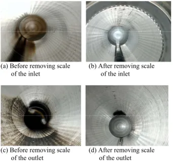
Fig. 2 shows the cold side surfaces of the heat exchanger before and after removing the scales. In fig. (d), partial scales remain on the top corner due to a flow dead zone of the agent circulation. As results, the scales were removed from the surface of the heat exchanger.
(a) Before removing scale (b) After removing scale of the inlet of the inlet
(c) Before removing scale (d) After removing scale of the outlet of the outlet Figure 2. Cleaning status after removing the scales
The major composition of the removed scales is an ignition loss, account for 64.59% of the total amount.
Transactions of the Korean Nuclear Society Autumn Meeting Busan, Korea, October 27-28, 2005
This result means that the cold water has no velocity and the deposits including microorganisms are accumulated on the cold side heat transfer plate of the heat exchanger during the reactor stop.
2.3 The effects after removing the scales
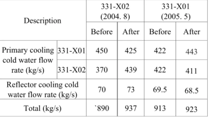
Table 1 shows the cold water flow rates including those after removing the scales of No.2 primary cooling heat exchanger (331-X02). After removing scales of the cold side in No. 1 primary cooling heat exchanger (331-X01), the cold water flow rate of the heat exchanger shows about 21 kg/s increase, but those of No.2 primary cooling heat exchanger and a reflector cooling heat exchanger shows about 11 kg/s and 1 kg/s decrease respectively. As results, the total cold water flow rate shows about 10 kg/s increase and the reactor cooling capability shows a 1.2% increase over before removing the scales.
2.4 Scale Removal Cycle
We reviewed the cold water flow rate of the primary heat exchangers to estimate a scale removal cycle. In general, the cold water flow rate of a heat exchanger is decided under consideration of fouling factor. In a clean condition, the heat exchanger gets an allowance of cooling capability. The allowance of the HANARO primary cooling heat exchanger is about 4.4%[3]. When the allowance converted to 40 kg/s of flow rate and the calculated minimum flow rate is 880 kg/s.
Fig. 3 shows a full power operation of the HANARO. Through the figure, it is confirmed that 890 kg/s of the cold water flow rate is available to cool the heat generated by a nuclear fission under a normal operation.
872 874 876 878 880 882 884 886 888 890 892 0 2 4 6 8 10 12 14 16 18 20
Measuring time (8 hours interval, 2004. 6/29-7/6)
R e a c tor c ooling c o ld w a te r f low r a te , kg /s 23 24 25 26 27 28 29 30 31 32 33 The rm a l pow e r, M W
Reactor cooling cold water Thermal power
Figure 3. Comparison of reactor cooling cold water flow rate and thermal power
As results, it is recommended that the scales of heat exchangers be removed when the total cold water flow rate falls to 890 kg/s, that is about 2.7% decrease over the cold water design flow rate under a normal operation.
3. Conclusions
The major composition of the removed scales is an ignition loss, which contains 64.59% of the total amount. After removing scales of the cold side in the primary cooling heat exchanger (331-X01), the total cold water flow rate shows about 10 kg/s increase and the reactor cooling capability shows a 1.2% increase over before removing scales. Therefore, under a full power operation it is recommended that the scales of heat exchangers be removed when the total cold water flow rate falls to 890 kg/s, that is about 2.7% decrease over the cold water design flow rate under a normal operation.
References
[1] HANSU LTD, "SSAKCLEAN RS II, Product report, CA-OT206-01-0401.
[2] Y. C, Park et al., "Removing Scales of the Primary Heat Exchanger in the HANARO,” the Proceedings of the Korean Nuclear Society Autumn Meeting Yongpyung, Korea, pp. 563-564, 2004.
[3] ALFA-LAVAL, "Instruction Manual - Plate Heat Exchanger,” IM70512-E1.
Table 1. Reactor cooling cold water flow rates after cleaning 331-X02
(2004. 8)
331-X01 (2005. 5) Description
Before After Before After 331-X01 450 425 422 443 Primary cooling
cold water flow
rate (kg/s) 331-X02 370 439 422 411 Reflector cooling cold
water flow rate (kg/s) 70 73 69.5 68.5 Total (kg/s) `890 937 913 923