https://doi.org/10.6113/JPE.2019.19.6.1515 ISSN(Print): 1598-2092 / ISSN(Online): 2093-4718
JPE 19-6-17
Synchronous Periodic Frequency Modulation
Based on Interleaving Technique to Reduce
PWM Vibration Noise
Wentao Zhang
*, Yongxiang Xu
†, Jingwei Ren
**, Jianyong Su
*, and Jibin Zou
*†,*Department of Electrical Engineering, Harbin Institute of Technology, Harbin, China **Hangzhou Applied Acoustics Research Institute, Hangzhou, China
Abstract
Ear-piercing high-frequency noise from electromagnetic vibrations in motors has become unacceptable in sensitive environments, due to the application of pulse width modulation (PWM) and in consideration of switching losses. This paper proposed a synchronous periodic frequency modulation (SPFM) method based on the interleaving technique for paralleled three-phase voltage source inverters (VSIs) to eliminate PWM vibration noise. The proposed SPFM technique is able to effectively remove unpleasant high-frequency vibration noise as well as acoustic noise more effectively than the conventional periodic carrier frequency modulation (PCFM) and interleaving technique. It completely eliminates the vibration noise near odd-order carrier frequencies and reduces the PWM vibration noise near even-order carrier frequencies depending on the switching frequency variation range. Furthermore, the SPFM method is simple to implement and does not employ additional circuits in the drive system. Finally, the effectiveness of the proposed method has been confirmed by detailed experimental results.
Key words: High-frequency PWM noise, Interleaving technique, Paralleled three-phase voltage source inverters, Periodic frequency
modulation
I. I
NTRODUCTIONPulse width modulation (PWM) based voltage source inverters (VSIs) are the driving force in industrial and commercial applications to meet the ever growing demand for energy efficiency, feature rich functionalities, and lower total cost of ownership [1]. However, it generates undesirable high-frequency PWM voltage and current harmonics during the intrinsic switching process [2]. The high-frequency harmonics are concentrated near the carrier frequency and its multiples [3], [4]. Moreover, the stator magneto-motive force (MMF) harmonics caused by the PWM current harmonics are an important part of electromagnetic radial forces. In fact, it is considered as the main source of electromagnetic vibration
[5], [6]. Meanwhile, the high-frequency vibration will generate acoustic noise within the hearing range. Hence, novel topologies and control strategies have been proposed to reduce the MMF produced by PWM current harmonics.
Paralleled interleaving topologies can replace each phase- leg with multiple phase-legs to increase the power level with carrier phase shift [7]-[8]. The application of this method was first made popular in dc-dc converters and voltage regulator modules, and has since spread into ac-dc and dc-ac converters for applications ranging from uninterruptible power supplies to active power filters, single-phase power factor correction (PFC), and three-phase voltage-source converters [7], [9], [10]. According to the authors of [11]-[12], symmetrically interleaving N voltage source converter modules cancels all of the harmonics except for the N-multiples of the carrier harmonic and their sideband components in both the output voltage and the dc-link current. For example, interleaving between two paralleled VSIs eliminates odd order carrier harmonics. However, the large inductors used to suppress circulating current are
© 2019 KIPE Manuscript receivedMar. 28, 2019; accepted Jun. 27, 2019
Recommended for publication by Associate EditorYongchang Zhang. †Corresponding Author: [email protected]
Tel: +86-13796638783, Harbin Institute of Technology *Dept. of Electrical Eng., Harbin Institute of Technology, China **Hangzhou Applied Acoustics Research Institute, China
obstacles to wide application [11], [12]. In addition, coupled inductors have been proposed to substitute inductors due to their small volume [7]. However, the symmetrical interleaving between two paralleled VSIs cannot impair the even-order carrier harmonics.
Moreover, combining a specially designed multi-phase permanent magnet synchronous motor (PMSM), particularly a dual three-phase PMSM, with the carrier phase shift technique also reduces PWM frequency noise. For dual three- phase PMSMs with two three-phase windings shifted by
, driven by interleaved paralleled inverters, the results in [13] reveal that vibration and sound pressure can be approximately halved at around twice the carrier frequency when the carrier phase is radians between each three- phase winding when compared to the conventional in-phase carrier PWM. Nevertheless, the resulting current harmonics due to the phase shift are not tackled properly. Shifting the carrier phase by for the two-segment three-phase PMSMs driven by interleaved paralleled VSIs without coupled inductors can only reduce vibration and torque ripple in terms of even-order carrier frequencies [14]. In addition, adding coupled inductors with the carrier phase shifted by also has an impact on vibration reduction due to decreasing of the current harmonics, whereas the vibration near odd carrier frequencies is not completely eliminated [15]. However, these methods fail to achieve reductions of both odd-order and even-order carrier harmonics.
A well-researched strategy to reduce voltage noise and acoustic noise is the random PWM-based (RPWM) technique [16]-[21]. When compared with the fixed switching frequency SVPWM technique, RPWM-based methods spread the power of noise over a wide range of the frequency domain, and the peak PWM noise in the phase voltage is reduced by about 9-10 dB [22]. The PCFM technique is similar to the RPWM and easier to achieve than the random function, whose carrier frequency varies as a periodic function [23], [24]. In fact, a shorter random frequency range weakens the effect of both the RPWM and the PCFM [22], [25]. Thus, decreases of the PWM noise in the phase voltage and phase current, especially in acoustic noise, is less than 10 dB in many situations.
The reduction of PWM frequency noise using only PCFM and RPWM is not enough in many applications. Therefore, this paper proposes a SPFM technique for paralleled three- phase VSIs. This technique can remove odd-order (1st, 3rd, 5th,…) carrier frequency noise and reduce even-order (2nd, 4th, 6th,…) noise. In other words, the SPFM technique can remove unpleasant PWM acoustic noise effectively with a shorter frequency range. Therefore, it is favorable for occasions demanding low acoustic noise.
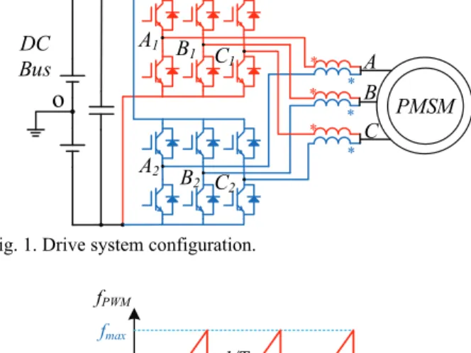
In this study, the proposed method is applied in a motor drive system that drives a three-phase PMSM with coupled inductors (CIs), as shown in Fig. 1. Coupled inductors are used to suppress the circulating currents between the two VSIs [7].
Fig. 1. Drive system configuration.
Fig. 2. Carrier frequency change law of the sawtooth periodic carrier frequency modulation.
In fact, the proposed method is practical in this drive system and in drive systems including dual three-phase motors with the interleaving technique, such as the topologies in [15].
The remainder of this paper is organized as follows. Section II introduces the proposed method. Section III analyzes an elimination principle for PWM vibrations. Section IV illustrates the obtained experimental results. Finally, some conclusions are made in section V.
II. I
NTRODUCTION OF THEP
ROPOSEDM
ETHODA. Review of Periodic Carrier Frequency Modulation
Different from the fixed carrier frequency, the carrier frequency change law of sawtooth periodic carrier frequency modulation is shown in Fig. 2, and the switching frequency change law is expressed as follows:
(1) where is the carrier frequency, is the central frequency, and is the carrier frequency variation. On the basis of Parseval theorem, the frequency-domain energy is kept constant when the time-domain energy distribution is unchanged [24]. Thus, the peak of harmonic amplitude decreases as the harmonic band width increases if frequency- domain energy remains constant. That is the basic principle for PWM noise reduction. It should be noted that the period of the sawtooth periodic carrier waveform and variation range influence the harmonic suppression.
Here, the parameter is defined as:
(2) / 6 / 2 / 2
o
A1 B1 C1 A2 B 2 C2 * * * * * * DC Bus PMSM A B C f0 fmin fmax t fPWM 1/T1 1/T2 1/T3 1/fm 2/fm
0
PWM c f t f t f t
PWM f t f t0
c f t 1 /fm
c f t = m e f f where is the frequency of the sawtooth periodic carrier waveform, and is the fundamental electrical frequency of the motor. When and are kept constant, is proportional to . Generally, the greater is, the higher the amplitude of the PWM harmonics become, since fewer frequency distribute energy. When , which means the frequency variation of the switching frequency cannot be finished in one fundamental cycle, it may have negative effects on the harmonic suppression and dynamic performance. Therefore, is a good choice for reference [25].
A wider switching frequency variation range leads to lower even-order carrier harmonics. Since is far smaller than , the range of the spread-spectrum near the k-order PWM harmonics can be written as:
(3)
It should be noted that when and ,
the spectrum between and overlap,
elevating the background noise between them. In practical applications, the range of the spread-spectrum and the parameter should be selected according to the application requirements.
B. Implementation of the Proposed Method
All of the orders of PWM harmonics still exists after using the PCFM. However, their peaks are reduced. In addition, the interleaving technique in paralleled VSIs is used to eliminate odd-order carrier harmonics. Therefore, the proposed method combines the advantages of the two technique. As shown in Fig. 3, the two-carrier wave of paralleled inverters are not in phase but have a phase shift. Moreover, the carrier period changes with time according to Fig. 2. The volt- seconds characteristic of the two VSIs are kept the same in any sub-cycle of PWM. Thus, the fundamental voltages of the two three-phase VSIs are kept the same to make the motor run normally. Hence, the reference wave of the PWM generation should be identical in one PWM cycle for the two inverters. The special design of the coupled inductors enables fundamental current to pass through without impedance. Moreover, if , the average switching frequency of one fundamental wave still maintains the center frequency f0. Therefore, the dynamic response of the proposed SPFM are not influenced.
Fig. 4 compares the effects of the suppression of PWM harmonics with four methods. The interleaving technique enables the elimination of the first and third carrier harmonics, and the PCFM spreads all of the orders of harmonics into a wider spectrum. The proposed method takes advantage of interleaving to eliminate the first carrier harmonics, and the PCFM to lower the amplitude of the PWM harmonics.
Fig. 3. Implementation of the proposed method.
Fig. 4. Spectrum analysis results of PWM harmonics with the SVPWM, PCFM, interleaving technique and SPFM when
.
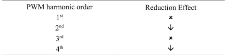
TABLE I
EFFECTS OF THE PROPOSED METHOD
PWM harmonic order 1st 2nd 3rd 4th Reduction Effect
Similarly, a wider switching frequency variation range leads to lower even-order carrier harmonics. As mentioned above, a much wider range of the switching frequency variation results in spectrum overlap for the PCFM, as can be seen in Fig. 4. It can also be seen in this figure that this is difficult for the SPFM, since the odd-order PWM harmonics are eliminated.
Therefore, the proposed method SPFM combines their advantages and reduces the drawbacks of both the periodic carrier frequency modulation and the interleaving technique in paralleled interleaved VSIs to reduce the PWM frequency harmonics. Table I demonstrates the effect of the proposed method, where means that the harmonics are totally eliminated and indicates that the harmonics are decreased.
III. A
NALYSIS OFPWM
N
OISEE
LIMINATION The vibration is closely related to PWM current harmonics. Thus, the current harmonics are analyzed in order to explain the principle of vibration elimination.m f e f e f f tc
m f fm 1 1
c f t m f PWM f 0 0 ( c) h ( c) k f f B k f f 2 k 1/ 5f0 fc 1/ 3f0 0 2(f fc) 3(f0 fc)
c f t 1 carrier wave1 T1 T2 T3 T1 T2 T3 dT1 dT2 dT3 dT1 dT2 dT3 PWM1 PWM2 carrier wave2 Frequency H ar m on ic A m pl itude SVPWM SPFM 0 c f f f0+fc 0 2 f-fc 2f0+fc 0 3 f-fc 3f0+fc f0 2f0 3f0 PCFM Interleaving 0 0 1 / 5f fc 1 / 3f(a)
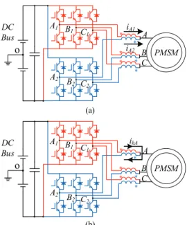
(b)
Fig. 5. Current moving path. (a) For fundamental current. (b) For odd-order PWM harmonic current.
A. PWM Current Harmonic Analysis
The PWM current harmonics in three-phase motors driven by paralleled VSIs with CIs are discussed in this section. The general harmonic form of a switched output waveform of a phase leg controlled by any carrier-based PWM scheme can be written as [26]:
(4)
(5)
where C0n is the amplitude of the fundamental/baseband voltage and Cmn is the amplitude of the carrier/sideband harmonics. and refer to the fundamental angular frequency and initial phase, respectively. and refer to the carrier harmonics angular frequency and initial phase, respectively. Moreover, m and n are positive integers that have opposite parities [5]. It can be seen that the output voltage can be divided into two parts: the fundamental component and the high-frequency PWM harmonics component . The proposed method has no effect on the fundamental component, and the two fundamental currents flow in the same direction, as can be seen in Fig. 5(a).
Focusing on the high-frequency harmonics part, the harmonics voltage in two VSIs have opposite directions but the same amplitudes, when the carrier phase is shifted by and m is
an odd number, namely . Moreover, the
windings on the magnetic core have the same impedance.
Thus, the corresponding current harmonics flow in the path shown in Fig. 5(b). They do not pass through the motor windings. In addition, the coupled inductors are used to reduce the odd-order carrier current harmonics. When m is
an even number, . The even-order PWM
harmonic currents flow like fundamental currents in Fig. 5(a), and exists in the three-phase windings. Due to periodic variations of the carrier frequency, the amplitude of
and are decreased. Consequently, the formed
by and is also suppressed.
The proposed method requires synchronous variation of the carrier wave to retain the interleaving. Therefore, the odd-order PWM harmonics no longer circulate in the motor. Periodic switching frequency modulation makes the amplitude of the even-order PWM current harmonics smaller due to the energy distribution.
B. Elimination Principle of Vibration Noise
Electromagnetic vibration noise mainly comes from radial electromagnetic forces, and based on the Maxwell tensor method, the radial electromagnetic force can be expressed as [27], [28]:
(6) where , which is related to space and time, is the radial air-gap flux density. is the space permeability. According to Hopkinson’s law, the PM magnetic field in the air gap can be derived as [29]:
(7) where means the air-gap MMF, and denotes the air-gap permeance. In fact, is composed of three parts: the MMF produced by the magnet magnetic field, the MMF produced by the armature reaction magnetic field, and the MMF produced by the high-frequency PWM magnetic field [29]. Hence,
can be expressed as:
(8) Furthermore, high-frequency MMF can be expressed as a product result of the winding turns and the PWM harmonic current :
(9)
where . When one of the teeth of stator is studied, the high- frequency o A1 B1 C1 A2 B 2 C2 * * * * * * DC Bus PMSM A B C iA1 iA2 o A1 B1 C1 A2 B 2 C2 * * * * * * DC Bus PMSM A B C ihA
1 1 0 0 0 1 1 0 0 1 cos( ) cos A O f h n n mn c c m n u t u t u t C n t C m t n t
2 2 0 0 0 1 2 0 0 1 cos( ) cos A O f h n n mn c c m n u t u t u t C n t C m t n t
0 0 c c
f u t
h u t
1 _h o 2 _h o u t u t
_ h o i t
1 _h e 2 _h e u t u t
1 _h e u t
2 _h e u t ih e_
t
1 _h e i t i2 _h e
t
2 0 , 2 r r B t p
, r B t 0
,
, , r B t f t t
, f t
,t
, f t
, m f t
, s f t
, h f t
, r B t
,
,
,
, , r m s h B t f t f t f t t ( ) h N ( ) h i t
2 2
0 , , 2 M h h r f t N i t t p
,
,
, M m s f t f t f t(a) (b) (c) (d)
Fig. 6. MMF produced by PWM harmonics for one tooth with: (a) SVPWM, (b) PCFM, (c) Interleaving technique, (d) SPFM.
electromagnetic radial force is only concerned with time harmonics, and (9) can be simplified as:
(10)
Fig. 6(a) illustrates the traditional SVPWM method, and the corresponding MMF is generated by odd-order and even-order carrier harmonic currents. The PCFM spreads the odd-order and even-order carrier harmonic currents and into a wider frequency spectrum. Thus, the amplitude of the MMF is reduced. The interleaving technique makes the odd-order carrier harmonics not flow in the motor windings. Thus, only the produced by remains. By comparison, the SPFM makes the odd-order PWM current harmonics not flow in the three-phase PMSM, and decreases the amplitude of the even-order PWM current harmonics , reducing the caused by the even- order carrier harmonics, as shown in Fig. 6(d).
Since the harmonic MMF generated by every coil on every tooth in the air gap is reduced, from the perspective of the whole motor, for every space position , only the even-order PWM harmonic MMF exists in the three-phase windings. However, it is reduced with the proposed method. Hence, the radial electromagnetic force declines. Therefore, the corresponding PWM vibration caused by PWM frequency current harmonics is suppressed with the proposed method.
IV. E
XPERIMENTALV
ALIDATION ANDA
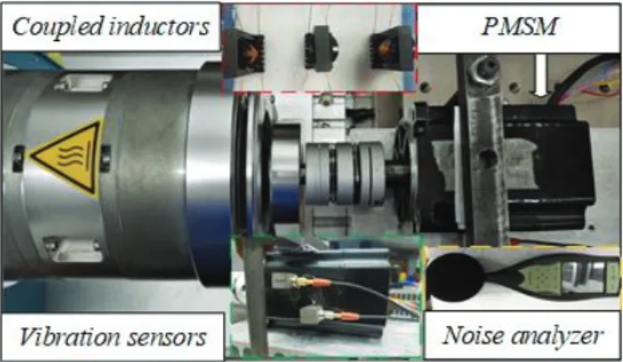
NALYSIS In this section, a PMSM drive system has been implemented to verify the capability of PWM noise reduction for PWM frequency vibrations with the SPFM. An experiment platform based on a MCU TMS320F28075 from Texas Instrument was set up to validate the above analysis and the test bench is shown in Fig. 7. Vibration sensors are glued to the motor surface to measure high-frequency vibrations. A Brüel & Kjær® 2250S noise analyzer is used to measure acoustic noise from the motor at a distance of 10 cm.Fig. 7. Test bench and experimental system.
TABLE II
PARAMETER OF THE EXPERIMENTAL SYSTEM
DC-link voltage Rated phase current Rated speed Phase resistance Phase inductance Resistance of CIs Inductance of Cis Center PWM frequency 70 V 1.5 A 1200 rpm 1.765 2.345 mH 0.302 8.0 mH 5 kHz
In addition, the coupled inductors are made by ‘EC’ ferrite cores with high permeability. A hysteresis dynamometer loads the motor.
The specifications and parameters of the drive system are listed in Table II. Sawtooth function modulation, as mentioned in Section II, is employed in the experimental validation. The PWM frequency of the PCFM and the SPFM range from 4.6 kHz to 5.4 kHz for part A, and from 4.0kHz to 6.0 kHz for part B, the average frequency of which is 5.0 kHz. This is due to the fact that a lower PWM frequency can reduce the demands of the measuring instruments, and the measurements are linear and precise. Experiments with the SVPWM, PCFM, interleaving and SPFM have been carried out to show the advantages of the proposed method in removing PWM noise. In the following results, the sampling frequency of the Fast Fourier Transform (FFT) for the signals
f
h_e(t)
i
h_e(t)
Magnet
Air gap
f
h_o(t)
f
h_e(t)
i
h_o(t)
i
h_e(t)
Magnet
f
h_e(t)
i
h_e(t)
Magnet
f
h_e(t)
i
h_e(t)
Magnet
i
h_o(t)
f
h_o(t)
Air gap
Air gap
Air gap
2 2
0 2 M h h rt f t N i t t p
_ ( ) h o i t _ ( ) h e i t _ ( ) h e f t ih e_ ( )t _ ( ) h o i t _ ( ) h e i t fh e_ ( )t (a)
(b)
(c)
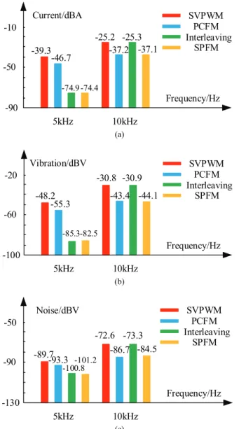
Fig. 8. Amplitude of the first and second PWM harmonics with four methods under a low modulation ratio for: (a) Current, (b) Vibration, (c) Noise.
in the oscilloscope is 250 kHz.
A. Results for Different Modulation Ratios
On the one hand, in order to fully verify the effectiveness of the proposed SPFM, it is necessary to examine experimental results for the PMSM working at different modulation ratios. On the other hand, PWM vibration noise is closely related to current harmonics. Once the current noise in the three-phase windings is reduced, the corresponding vibration noise is eliminated. Moreover, high-frequency noise also reflects vibrations. Thus, current waveforms, vibration signals and noise signals ( ) are all provided.
When the PMSM works at a low modulation ratio (0.3), that is 480 r/min and 0.2 Nm, the harmonic amplitude of phase current A using the SVPWM, PCFM, interleaving and SPFM are compared. As shown in Fig. 8(a), the traditional
(a)
(b)
(c)
Fig. 9. Amplitude of the first and second PWM harmonics with four methods under a medium modulation ratio for: (a) Current, (b) Vibration, (c) Noise.
SVPWM technique has the highest amplitude of high- frequency PWM current harmonics in terms of 5.0 kHz and 10.0 kHz. When compared with the SVPWM, the PCFM lowers the amplitudes of 7.4 dBA and 12.0 dBA by widening the harmonics spectrum. The interleaving technique nearly eliminates the first carrier harmonics at the level of the background noise. However, it has no impact on the second carrier harmonics. By comparison, the SPFM eliminates the first carrier harmonics and lowers the second carrier harmonics like the PCFM. Similar results can be found in Fig. 8 (b) and (c) for vibration and noise. The vibration signal with the SPFM decreases by 34.3 dBV and 13.3 dBV at the first and second carrier harmonics when compared with the SVPWM. For high-frequency PWM acoustic noise, the proposed SPFM also significantly reduces the noise amplitude.
The results for a medium modulation ratio (0.5) are also -90 Current/dBA -10 -50 -39.3 -46.7 -74.9 -74.4 -25.2 -37.2 -25.3 -37.1 5kHz Frequency/Hz 10kHz SVPWM PCFM Interleaving SPFM -100 Vibration/dBV -20 -60 -48.2 -55.3 -85.3-82.5 -30.8 -43.4 -30.9 -44.1 5kHz Frequency/Hz 10kHz SVPWM PCFM Interleaving SPFM -130 Noise/dBV -50 -90 -89.7-93.3 -100.8-101.2 -72.6 -86.7 -73.3 -84.5 5kHz Frequency/Hz 10kHz SVPWM PCFM Interleaving SPFM =1 -90 Current/dBA -10 -50 -30.5 -39.0 -72.3-72.6 -23.1 -35.8 -23.0 -34.2 5kHz Frequency/Hz 10kHz SVPWM PCFM Interleaving SPFM -100 Vibration/dBV -20 -60 -38.0 -48.0 -80.4-80.0 -28.7 -41.3 -28.8 -39.7 5kHz Frequency/Hz 10kHz SVPWM PCFM Interleaving SPFM -130 Noise/dBV -50 -90 -75.9 -83.6 -89.7-91.1 -75.6 -80.4-73.7-80.9 5kHz Frequency/Hz 10kHz SVPWM PCFM Interleaving SPFM
(a) (b)
(c) (d)
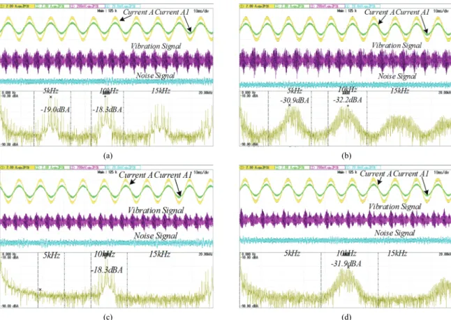
Fig. 10. Waveforms and spectrum of the current A signal under a high modulation ratio with: (a) SVPWM, (b) PCFM, (c) Interleaving, (d) SPFM.
demonstrated in Fig. 9, which shows similar results in terms of PWM noise reduction as Fig. 8. Although the amplitude of the PWM harmonics are all elevated for the current, vibration and noise, the effect on harmonic reduction is not affected. For vibration signals, when focusing on the first carrier harmonics, the SPFM achieves almost the same reduction as the interleaving technique. It also decreases by 11.0 dBV similar to the PCFM for the second PWM harmonics.
When the motor runs under a high modulation ratio (0.75), as shown in Fig. 10(a), the PWM current noise concentrates on 5.0 kHz and its multiples for the conventional SVPWM. With the PCFM, the switching frequency varies from 4.6 kHz to 5.4 kHz as sawtooth function variation law. The amplitude of the first carrier current harmonics is 11.9 dBA less than the fixed switching frequency SVPWM, and that of second carrier harmonics is 13.9 dBA. As can be seen in Fig. 10 (c), the interleaving technique almost completely eliminates the first carrier harmonics at 5.0 kHz. It can also be seen that it has almost the same amplitude of the second carrier harmonics as the SVPWM. With the SPFM, the first PWM current noise is totally eliminated with the interleaving technique, while the second is reduced by 13.6 dBA. With the PCFM technique, the first PWM harmonics can only be distributed. However, it is removed with the SPFM like the interleaving technique. For the second PWM noise, the PCFM and the SPFM both spread the harmonics from 9.2
kHz to 10.8 kHz.
The PWM technique has a direct impact on high-frequency vibration. As shown in Fig. 11(b), when comparing the results of the fixed switching frequency in Fig. 11(a) with those of the PCFM, it can be seen that the first PWM vibration noise decreases by 5.7 dBV, and by 8.5 dBV for the second PWM harmonics. The effect on the reduction of the PWM vibration noise is not obvious for the PCFM, and the PWM noise energy still remains high. As a result, it does not satisfy the noise demands in many applications. The interleaving technique removes the first carrier harmonics, which reduces the amplitude of the vibration signal, as can be seen in Fig. 11(c). With the proposed SPFM, the amplitude of the first PWM vibration noise no longer exists and the second PWM vibration noise can be reduced.
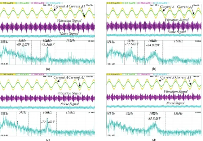
Once the high-frequency PWM vibration is reduced, the corresponding acoustic noise is also eliminated. The motor acoustic noise caused by PWM harmonics is measured by a Brüel & Kjær® 2250S noise analyzer. In fact, the mechanical noise is also received by the analyzer. As shown in Fig. 12(b), the first PWM acoustic noise with the PCFM is decreased by 3.3 dBV, and the second PWM noise is reduced by 10.7 dBV when compared with the results of the fixed frequency SVPWM. Although interleaving technique reduces the first carrier harmonics, the amplitude of the second harmonics still remain unchanged. By contrast, the proposed SPFM shown in
(a) (b)
(c) (d)
Fig. 11. Waveforms and spectrum of the vibration signal under a high modulation ratio with: (a) SVPWM, (b) PCFM, (c) Interleaving, (d) SPFM.
(a) (b)
(c) (d)
Fig. 12. Waveforms and spectrum of the noise signal under a high modulation ratio with: (a) SVPWM, (b) PCFM, (c) Interleaving, (d) SPFM.
(a)
(b)
(c)
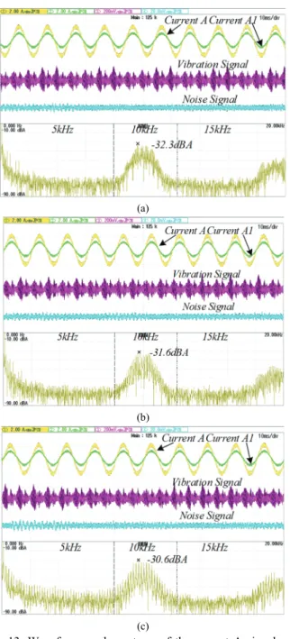
Fig. 13. Waveforms and spectrum of the current A signal with the SPFM when: (a) , (b) , (c) .
Fig. 12(d) completely reduces the first PWM acoustic noise and decreases the second PWM acoustic noise by 10.5 dBV with the same effect as the PCFM. If a better reduction effect is required, a wider variation range of the switching frequency is implemented.
B. Results for Different Period of a Sawtooth Periodic Waveform
Fig. 13 demonstrates the spectrum of the phase current
when , and , where . For the
proposed SPFM, the larger is, the less frequency is distributed to decrease the amplitude of the harmonics. Therefore, the spectrum of the second carrier harmonics
(a)
(b)
(c)
Fig. 14. Waveforms and spectrum of the vibration signal with the SPFM when: (a) , (b) , (c) .
becomes sparser and the amplitude of the second carrier harmonics get larger as increases. However, the amplitude difference is not obvious. Moreover, the harmonics in Fig. 13(c) obviously increase and lift the background noise. When , the variation of the switching frequency cannot finish in one fundamental cycles, which makes the dynamic response of one fundamental current waveform different from that of the next period. However, a smaller makes the energy distributed in more of the frequency domain. Based on comprehensive consideration, is recommended.
In Fig. 14, the results are line with the Fig. 13. When , more harmonics are introduced into the spectrum of the vibration signal. Thus, although the reduction difference
0.5 1 2 0.5 1 2 fe=100Hz 0.5 1 2 0.5 1 2
(a) (b)
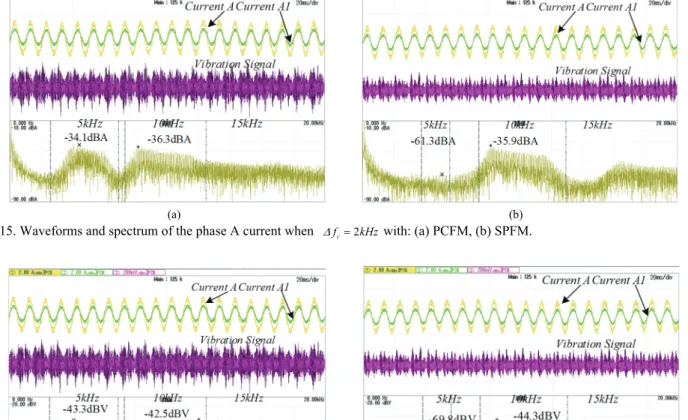
Fig. 15. Waveforms and spectrum of the phase A current when with: (a) PCFM, (b) SPFM.
(a) (b)
Fig. 16. Waveforms and spectrum of the vibration signal when with: (a) PCFM, (b) SPFM.
is not obvious for different , using is a good choice.
C. Results for the Variation Range of PWM Frequency
As analyzed in part A of section II, a wider range leads to a lower harmonic amplitude. However, the PCFM has a disadvantage in terms of spectrum overlap, which elevates the background noise. To verify the analysis and highlight the advantage of the SPFM mentioned above, the range of the switching frequency is varied between 4.0 kHz to 6.0 kHz. Thus, the second-time switching frequency variation changes from 8.0 kHz to 12.0 kHz, the third-time switching frequency varies from 12.0 kHz to 18.0 kHz, and the fourth-time switching frequency ranges from 16.0 kHz to 24.0 kHz. One the one hand, when compared with Fig. 10(b), the amplitude of first and second PWM harmonics in Fig.15(a) decrease by 3.2 dBA and 4.1 dBA, respectively. One the other hand, a wide spread-spectrum leads to an overlap between 12.0 kHz to 16.0 kHz. However, in Fig. 15(b), the second carrier harmonics is reduced and the overlapping spectrum changes into background noise, since the harmonics between 12.0 kHz to 16.0 kHz are eliminated by interleaving.
For the vibration signals in Fig. 16(b), the spectrum results are consistent with the current spectrum analysis. It is obvious that the background noise is lifted by the PCFM.
Meanwhile, the SPFM can effectively improve the overlap.
V. C
ONCLUSIONSThe proposed SPFM method combing interleaving technique with PCFM is illustrated and implemented on paralleled VSIs with coupled inductors to eliminate high- frequency PWM vibration and acoustic noise.
The electromagnetic vibration of a three-phase motor is closely related to the current harmonics. The proposed SPFM makes the odd-order PWM current harmonics not flow in the three-phase windings, and spreads the even-order PWM harmonics into a wide range. Thus, it generates no odd-order carrier MMF harmonics and reduces the even-order carrier MMF harmonics in the air gap.
The experimental results verify the analysis of the vibration elimination principle and the advantages of the proposed method. Once the current harmonics are reduced, the corresponding vibration can be suppressed. The proposed technique can significantly remove the first PWM noise and decrease the second PWM noise under different modulation ratios. Elimination of the odd-order carrier harmonics helps to avoid spectrum overlap. In practical applications, appropriate values for the period of the sawtooth periodic carrier
2 c f kHz 2 c f kHz 1
waveform and the range of the switching frequency variation can be chosen depending on their requirements.
A
CKNOWLEDGMENTThis work was supported by the National Natural Science Foundation of China under Grant 51577036 and Grant 51437004.
R
EFERENCES[1] K. Lee, G. Shen, W. Yao, and Z. Lu, “Performance characterization of random pulse width modulation algorithms in industrial and commercial adjustable-speed drives,” IEEE Trans. Ind. Appl., Vol. 53, No. 2, pp. 1078-1087, Mar./Apr., 2017.
[2] D. G. Holmes and T. A. Lipo, Pulse Width Modulation for Power Converters: Principles and Practice, Wiley, chap.1, 2003.
[3] W. Liang, J. Wang, P. C. Luk, W. Fang, and W. Fei, “Analytical modeling of current harmonic components in PMSM drive with voltage-source inverter by SVPWM technique,” IEEE Trans. Energy Convers., Vol. 29, No. 3, pp. 673-680, Sep. 2014.
[4] Y. Huang, Y. Xu, Y. Li, G. Yang, and J. Zou, “PWM frequency voltage noise cancelation in three-phase VSI using the novel SVPWM strategy,” IEEE Trans. Power Electron., Vol. 33, No. 10, pp. 8596-8606, Oct. 2018. [5] J. L. Besnerais, V. Lanfranchi, M. Hecquet, and P. Brochet,
“Characterization and reduction of audible magnetic noise due to PWM supply in induction machines,” IEEE Trans. Ind. Electron., Vol. 57, No. 4, pp. 1288-1295, Aug. 2010. [6] R. Islam and I. Husain, “Analytical model for predicting
noise and vibration in permanent-magnet synchronous motors,” IEEE Trans. Ind. Appl., Vol. 46, No. 6, pp. 2346- 2354, Apr. 2010.
[7] D. Zhang, F. Wang, R. Burgos, R. Lai, and D. Boroyevich, “Impact of interleaving on AC passive components of paralleled three-phase voltage-source converters,” IEEE Trans. Ind. Appl., Vol. 46, No. 3, pp. 1042-1054, May/Jun. 2010.
[8] M. A. Abusara and S. M. Sharkh, “Design and control of a grid-connected interleaved inverter,” IEEE Trans. Power Electron., Vol. 28, No. 2, pp. 748-764, Jun. 2013.
[9] L. Asiminoaei, E. Aeloiza, P. N. Enjeti, and F. Blaabjerg, “Shunt active-power-filter topology based on parallel interleaved inverters,” IEEE Trans. Ind. Electron., Vol. 55, No. 3, pp. 1175-1189, Mar. 2008.
[10] J. Tsai, T. Wu, C. Wu, Y. Chen, and M. Lee, “Interleaving phase shifters for critical-mode boost PFC,” IEEE Trans. Power Electron., Vol. 23, No. 3, pp. 1348-1357, May 2008. [11] S. K. T. Miller, T. Beechner, and J. Sun, “A comprehensive study of harmonic cancellation effects in interleaved three- phase VSCs,” in IEEE Power Electronics Specialists Conference, Orlando, pp. 29-35, 2007.
[12] T. Beechner and J. Sun, “Asymmetric interleaving – A new approach to operating parallel converters,” in IEEE Energy Conversion Congress and Exposition, pp. 99-105, 2009.
[13] Y. Miyama, M. Ishizuka, H. Kometani, and K. Akatsu, “Vibration reduction by applying carrier phase-shift PWM on dual three-phase winding permanent-magnet synchronous motor,” IEEE Trans. Ind. Appl., Vol. 54, No. 6, pp. 5998- 6004, Nov./Dec. 2018.
[14] X. Han, D. Jiang, T. Zou, R. Qu, and K. Yang, “Two- segment three-phase PMSM drive with carrier phase-shift PWM for torque ripple and vibration reduction,” IEEE Trans. Power Electron., vol 34, No. 1, pp. 588-599, Jan. 2019.
[15] Y. Huang, Y. Xu, W. Zhang, and J. Zou, “PWM frequency noise cancellation in two-segment three-phase motor using parallel interleaved inverters,” IEEE Trans. Power Electron., Vol. 34, No. 3, pp. 2515-2525, Mar. 2019.
[16] A. M. Trzynadlowski, F. Blaabjerg, J. K. Pedersen, R. L. Kirlin, and S. Legowski, “Random pulse width modulation techniques for converter-fed drive systems-a review,” IEEE Trans. Ind. Appl., Vol. 30, No. 5, pp. 1166-1175, Sep/Oct, 1994.
[17] M. M. Bech, F. Blaabjerg, and J. K. Pedersen, “Random modulation techniques with fixed switching frequency for three-phase power converters,” IEEE Trans. Power Electron., Vol. 15, No. 4, pp. 753-761, Jul. 2000.
[18] R. L. Kirlin, M. M. Bech, and A. M. Trzynadlowski, “Analysis of power and power spectral density in PWM inverters with randomized switching frequency,” IEEE Trans. Ind. Electron., Vol. 49, No. 2, pp. 486-499, Apr. 2002. [19] A. C. B. Kumar and G. Narayanan, “Variable-switching
frequency PWM technique for induction motor drive to spread acoustic noise spectrum with reduced current ripple,” IEEE Trans. Ind. Appl., Vol. 52, No. 5, pp. 3927-3938, Sep./Oct. 2016.
[20] A. Ruiz-Gonzalez, F. Vargas-Merino, J. R. Heredia-Larrubia, M. J. Meco-Gutierrez, and F. Perez-Hidalgo, “Application of slope PWM strategies to reduce acoustic noise radiated by inverter-fed induction motors,” IEEE Trans. Ind. Electron., Vol. 60, No. 7, pp. 2555-2563, Dec. 2013. [21] J. Xu, Z.-L. Nie, and J.-J. Zhu, “An optimal random carrier
pulse width modulation technique based on a genetic algorithm,” J. Power Electron., Vol. 17, No. 2, pp. 380-388, Mar. 2017.
[22] K. Kim, Y. Jung, and Y. Lim, “A New hybrid random PWM scheme,” IEEE Trans. Power Electron., Vol. 24, No. 1, pp. 192-200, Jan. 2009.
[23] X. Yongxiang, Y. Qingbing, Z. Jibin, W. Baochao, and L. Junlong, “Periodic carrier frequency modulation in reducing low-frequency electromagnetic interference of permanent magnet synchronous motor drive system,” IEEE Trans. Magn., Vol. 51, No. 11, pp. 1-4, Nov. 2015.
[24] Y. Xu, Q. Yuan, J. Zou, and Y. Li, “Analysis of triangular periodic carrier frequency modulation on reducing electromagnetic noise of permanent magnet synchronous motor,” IEEE Trans. Magn., Vol. 48, No. 11, pp. 4424-4427, Nov. 2012.
[25] Y. Xu, Q. Yuan, J. Zou, Y. Yao, and G. Zhu, “Sinusoidal periodic carrier frequency modulation in reducing electromagnetic noise of permanent magnet synchronous motor,” IET Electr. Power Appl. , Vol. 7, No. 3, pp. 223-230, 2013.
[26] D. G. Holmes and B. P. McGrath, “Opportunities for harmonic cancellation with carrier-based PWM for a two-level and multilevel cascaded inverters,” IEEE Trans. Ind. Appl., Vol. 37, No. 2, pp. 574-582, Mar./Apr. 2001. [27] Z. Q. Zhu, Z. P. Xia, L. J. Wu, and G. W. Jewell, “Analytical
modeling and finite-element computation of radial vibration force in fractional-slot permanent-magnet brushless machines,” IEEE Trans. Ind. Appl., Vol. 46, No. 5, pp. 1908-1918, Sep./Oct. 2010.
[28] W. C. Lo, C. C. Chan, Z. Q. Zhu, X. Lie, D. Howe, and K. T. Chau, “Acoustic noise radiated by PWM-controllel induction machine drives,” IEEE Trans. Ind. Electron., Vol. 47, No. 4, pp. 880-889, Aug. 2000.
[29] W. Liang, P. C. Luk, and W. Fei, “Analytical investigation of sideband electromagnetic vibration in integral-slot PMSM drive with SVPWM technique,” IEEE Trans. Power Electron., Vol. 32, No. 6, pp. 4785-4795, Jun. 2017.
Wentao Zhang received his B.S. degree in Electrical Engineering and Automation from the Harbin Institute of Technology, Weihai, China, in 2016, where he is presently working towards his Ph.D. degree. His current research interests include PMSM drives and control algorithms.
Yongxiang Xu was born in Guangxi Province, China, in 1977. He received his M.S. and Ph.D. degrees in Electrical Engineering from the Harbin Institute of Technology (HIT), Harbin, China, in 2001 and 2005, respectively. He is presently working as a Professor in the State Key Laboratory of Robotics and System, HIT. His current research interests include permanent-magnet machine design and control.
Jingwei Ren was born in Chengde, Hebei Province, China, in 1988. He received his M.S. degree in Control Engineering from Yanshan University, Qinhuangdao, China, in 2016. He is presently working in Hangzhou Applied Acoustics Research Institute, Hangzhou, China. His current research interests include control algorithms and engineering applications of permanent magnet synchronous machines (PMSMs).
Jianyong Su was born in China, in 1979. He received his B.S., M.S. and Ph.D. degrees in Electrical Engineering from Harbin Institute of Technology (HIT), Harbin, China, in 2002, 2004 and 2009, respectively. Since 2010, he has been working as an Associate Professor in the School of Electrical Engineering and Automation, HIT. From June 2015 to May 2016, he was a Visiting Scholar at North Carolina State University, Raleigh, NC, USA. His current research interests include permanent magnet synchronous motors (PMSMs), multi-phase PMSMs, low voltage IMs, sensorless control and field-weakening control.
Jibin Zou was born on January 19, 1957, in Heilongjiang Province, China. He received his M.S. and Ph.D. degrees in Electrical Engineering from the Harbin Institute of Technology (HIT), Harbin, China, in 1984 and 1988, respectively. For one year, he was a Visiting Research Fellow at the University of Liverpool, Liverpool, ENG, UK. He is presently working as a Professor in the State Key Laboratory of Robotics and System, HIT. Since 2000, Professor Zou has been a Senior Member of the IEEE Magnetics Society. His current research interests include permanent-magnet machine design and control.