2301
Copyright ⓒ The Korean Institute of Electrical Engineers
Differential Evolution Approach for Performance Enhancement of
Field-Oriented PMSMs
Hong Min Yun*, Yong Kim* and Han Ho Choi
†Abstract
– In a field-oriented vector-controlled permanent magnet synchronous motor (PMSM) control system, the d-axis current control loop can offer a free degree of freedom which can be used to improve control performances. However, in the industry the desired d-axis current command is usually set as zero without using the free degree of freedom. This paper proposes a method to use the degree of freedom for control performance improvement. It is assumed that both the inner loop proportional-integral (PI) current controller and the q-axis outer loop PI speed controller are tuned by the well-known tuning rules. This paper gives an optimal d-axis reference current command generator such that some useful performance indexes are minimized and/or a tradeoff between conflicting performance criteria is made. This paper uses a differential evolution algorithm to autotune the parameter values of the optimal d-axis reference current command generator. This paper implements the proposed control system in real time on a Texas Instruments TMS320F28335 floating-point DSP. This paper also gives experimental results showing the practicality and feasibility of the proposed control system, along with simulation results.Keywords:
Permanent magnet synchronous motor (PMSM), Field-oriented control, Speed control, Proportional-integral (PI) control, Differential evolution (DE).1. Introduction
Permanent magnet synchronous motors (PMSMs) are widely used in many industry due to their low noise, high efficiency, and robustness. Various advanced methods to precisely control PMSMs have been proposed in the literature, but most popular and simple PMSM systems are based on a field-oriented proportional-integral (PI) control system containing two control loops: the inner loop PI current control loop and the outer loop PI speed control loop [1-9]. The outer loop PI speed control loop generates the q-axis reference current command (iqd) by using the
reference speed error signal. The inner loop PI current control loop makes the d and q-axis current (id, iq) track
accurately the d-and q-axis reference command (idd, iqd). In
the fieloriented vector controlled PMSM system, the d-axis current command (idd) can be set freely within some
range and thus this offers a free degree of freedom which can be used to handle some useful control performance criteria. However, in the industry the d-axis current command (idd) is usually set as zero in order to avoid
demagnetizing the permanent magnet, and almost all the field-oriented surface mounted PMSM control methods use this zero d-axis current control approach. This zero d-axis current control approach leads to a simple control system
structure. The maximum torque per ampere methods such as [7-9] also lead to zero d-axis current control laws in case of surface mounted PMSMs. However, the conventional zero d-axis current controllers result in high back electro-motive force and very narrow operating speed ranges. A nonzero d-axis current control methods should be used to expand the operating speed range of a PMSM above the rated speed as shown in [10, 15].
Considering these facts, we propose a controller to generate an optimal d-axis reference current command for a field-oriented vector-controlled PMSM based on differential evolution (DE) approach which has been successful in solving many difficult engineering optimi-zation problems. First, we illustrate a field-oriented vector-controlled PMSM system. And we formulate our problem of designing the d-axis reference current command generator minimizing some useful control performance indexes. We will assume that the inner loop PI current controller as well as the q-axis outer loop PI speed controller is tuned by the well developed tuning rules in the literature. Secondly, we give a DE-based algorithm to optimize and autotune the d-axis reference current command generator under some performance criteria. The criteria can be any weighted sum of the useful control performance indexes such as integral of absolute error (IAE), integral of squared error (ISE), integral of time-weighted absolute error (ITAE), integral of time-time-weighted squared error (ITSE), copper loss, iron loss, magnitude of state, stator current magnitude, stator voltage magnitude, and or so. Thus the proposed control method can give
† Corresponding Author: Div. of Electrical and Electronic Engineering, Dongguk Univ.-Seoul, Korea. ([email protected])
* Div. of Electrical and Electronic Engineering, Dongguk Univ.-Seoul, Korea. ([email protected], [email protected])
better performances than conventional zero d-axis current control methods. It should be noted that many loss minimization methods such as [4, 7] can be found in the literature but unlike the proposed method they cannot be used to make a tradeoff between energy loss and other important control performance indexes such as stator current magnitude, stator voltage magnitude, IAE, ISE, ITAE, ITSE, etc. Finally, we implement the proposed DE-based d-axis current control algorithm on a Texas Instruments TMS320F28335 DSP to show the effectiveness of the proposed method and we give simulation and experimental results to confirm that the proposed method can be successfully applied to the real-time PMSM control design problem.
2. Problem Formulation
If we use the rotor coordinates of the motor as reference coordinates, we can describe a surface mounted PMSM dynamics by the following nonlinear equation [3]:
1 2 3 4 5 6 4 6 q L q q d q d d d d i T i i i V i i i V w r r w r r r w w r r w r = - -= - - + + = - + + & & & (1)
where TL represents the load torque, ω = dθ/dt is the
electrical rotor angular speed, θ is the electrical rotor angle, iq is the q-axis current, Vq is the q-axis voltage, id is the
d-axis current, Vd is the d-axis voltage, and ρi > 0, i = 1, … ,
6 are the parameter values given by
2 1 2 3 4 5 6 3 1 , , , 2 4 2 1 , , m s m s s s p B p J J J R L L L r f r r f r r r = = = = = = (2)
and p is the number of poles, Rs, Ls, J, B, φm are the stator
resistance, the stator inductance, the rotor inertia, the viscous friction coefficient, the magnetic flux. Fig. 1 shows a block diagram of a general field-oriented vector control system for a PMSM. As can be seen in Fig. 1 a field-oriented vector-controlled system consists of two control loops: the inner loop PI current control loop and the outer loop PI speed control loop. In the inner loop current control
loop, the q-and d-axis voltage input (Vq, Vd) is generated by
the following PI control law in order to make the d-and q-axis current (id, iq) track accurately the d-and q-axis
reference command (idd, iqd) : 0 0 ( ) ( ) ( ) ( ) t q Pi qd q Ii qd q t d Pi dd d Ii dd d V K i i K i i d V K i i K i i d t t = - + -= - +
-ò
ò
(3)where KPi and KIi denote the P and I gains of the inner loop
PI current controller and (iqd, idd) is the q-and d-axis
reference command. The inner loop PI current controller gain is usually determined by the well-known tuning rules [1, 2] as follows :
,
Pi s I Ii s I
K =Lw K =Rw (4)
where ωI is the bandwidth of the inner loop PI current
controller. In order to cancel out the coupling terms we can insert some decoupling terms into the above PI controller and we can use the following modified inner loop PI-type current controller 0 0 ( ) ( ) ( ) ( ) t q s d m Pi qd q Ii qd q t d s q Pi dd d Ii dd d V L i K i i K i i d V L i K i i K i i d w wf t w t = + + - + -= - + - +
-ò
ò
(5)By the above inner loop PI current controller, we can obtain the following first-order speed loop dynamics :
1iq 2 3TL
w&=r -r w-r (6)
which can be used to design the q-axis outer loop PI speed controller or equivalently determine the q-axis reference current command iqd. The command iqd is generated by the
following PI control law
0 t
qd Ps e Is e
i = -K w -K
ò
w td (7)where ωe = ω-ωd, ωd is the reference rotor speed, KPs and
KIs denote the P and I gains of the outer loop PI speed
controller. The well-known tuning rules [2] imply that the PI speed controller gain can be determined by
2 2
1 1
1.414 / , /
Ps I Is I
K = w fr K =w f r (8)
where φ is usually chosen as φ ≥10. In the industry the daxis reference current command idd is usually set as idd = 0
while the q-axis reference current command iqd is
computed by the above PI speed control law (7). There exists a degree of freedom in the d-axis current loop because the d-axis reference current command idd can be
set freely within a range guaranteeing the hardware constraints
2 2 2 2 2 2
max, max
q d q d
V +V £V i +i £I (9)
Fig. 1. Schematic diagram of a field-oriented PMSM
where Vmax is the maximum stator voltage which is usually
equal to the voltage rating and Imax is the maximum stator
current. This degree of freedom in the d-axis current loop can be used to handle some useful control performance criteria.
We will assume that as shown in Fig. 2 the d-axis current reference command idd can be represented by the following
N-th order polynomial function of iqd :
After all, our design problem can be formulated as proposing a stability analysis and control synthesis method for the error dynamics (2). Fig. 2 shows a block diagram of the PI controller for a boost converter.
2 0 1 2 0 N k N dd i qd qd qd N qd k i ai a ai a i a i = =
å
= + + +L+ (10)where α0, … , αN are design parameters. Because the four
indexes IAE, ISE, ITAE, and ITSE are most commonly used measures to compare the control performances of PID control systems, we will consider the following performance indexes to find the optimal idd
2 2 0 | | , 0 | | , 0 , 0 f f f f t t t t e dt t e dt edt t edt w w w w
ò
ò
ò
ò
(11)where tf is the simulation time or final time. The following
performance criterion can be used to limit the magnitudes of the stator current and voltage
0 f t T x Qxdt
ò
(12)where Q is a positive semidefinite 4 by 4 matrix and x = [iq, id, Vq, Vd]TÎR4, and thus we will consider the above
control performance index.
After all, our design problem can be formulated as an optimization problem of finding the optimal parameter vector α = [α0, … , αN]TÎRN+1 such that the following
integral performance index J is minimized for the given PI gains KPi, KIi, KPs, KPs. 2 2 1 2 3 4 0 ( | | | | ) f t T e e e e J=
ò
b w +b w +bt w +b wt +x Qx dt (13) where β1, β2, β3, and β4 are positive weighting factors. Theoptimization problem can be rewritten as
arg min ( )
(1), (4), (6), (8), (9) J
subject to
a a (14)
Because the optimization problem (14) is difficult to solve analytically, we try to use a DE algorithm to find the
optimal parameter vector α.
Remark 2.1: The previous results such as [4] imply that
the total electrical loss Ploss is given by
2 2 2 2
1.5 [( ) ( ) ] 1.5 ( )
loss s q qi d di i qi di
P = R i +i + i +i + R i +i (15)
where Ri is the iron loss resistance, idi is the d-axis iron loss
current, and iqi is the q-axis iron loss current. Thus the
wasted power work due to the electrical loss during the time interval [0, tf ] can be given by
2 2 2 2
0
1.5 tf ( ) ( ) ( )
E s q qi s d di i qi di
W =
ò
éëR i +i +R i +i +R i +i ùûdt(16) And therefore, by including WE in the performance indexof (13) we can make a tradeoff between energy loss and the most commonly used control performance indexes. Because the iron loss resistance Ri is much greater than
the stator reactance, the total electrical loss can be approximated as
[
]
2 2 2 2 2 2 1.5 ( ) 1.5 ( ) / loss s q d s q m s d i P » R i +i + w L i + f +L i R (17)thus we may use the following index instead of (16)
[
]
2 2 2 2 2 2 0 1.5 tf ( ) ( ) E s q d s q m s d i W R i i L i L i dt R w f é ù » ê + + + + ú ë ûò
(18)3. Differential Evolution Algorithm to Design
d-axis Reference Current Command Generator
Our design problem (14) is nonlinear and it seems difficult to solve analytically or numerically. In order to solve such nonlinear problems nature-inspired algorithms such as genetic algorithm, particle swarm optimization, and DE have recently been introduced by many researchers. Some researchers have compared the various nature-inspired evolutionary algorithms and they have reported that in spite of its simplicity DE generally outperforms other nature-inspired evolutionary algorithms in some aspects [11-14]. The number of control parameters of DE is very few, and thus DE is very simple and easy to implement compared with other nature-inspired evolutionary algorithms. In DE Np solution candidates of an
Nv-dimensional space optimization problem are
represented as a population of size Np of Nv-dimensional
vectors ranging within which the candidates should be restricted. The vectors are also called chromosomes or genomes. The k-th generation population of size Np of Nv
-dimensional chromosomes Pki are shown in Fig. 3. Like
other genetic algorithms DE emulates three basic natural genetic operators: mutation, crossover, selection. In mutation process, for each chromosome or target vector a mutant vector is generated by mutation of three randomly selected chromosomes from the current generation excluding the
Fig. 2. Block diagram of the d-axis reference current
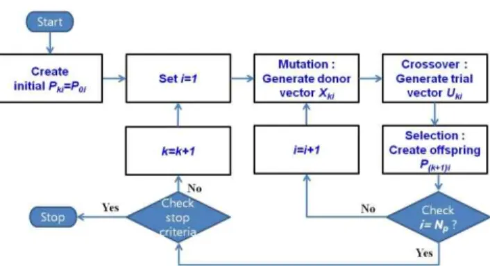
target vector. Crossover operation exchanges some elements of the mutant vector (also called donor vector) with the target vector to generate the trial vector. In selection process, the target vector and the trial vector are rated by using the objective function to be minimized and the better vector survives to the next population. A DE algorithm usually starts with generating an initial population randomly like other genetic algorithms. And then the three main evolutionary steps of mutation, crossover, selection are repeated until some stopping criteria are satisfied.
In this section, we propose an autotuning method for the d-axis reference current command generator based on DE approach. Fig. 3 shows a flow chart of the proposed DE algorithm to autotune the parameters of the d-axis reference current command generator.
3.1 Initialization
Before we actually start to optimize and autotune the d-axis reference current command generator, we need to set the essential parameters of the maximum generation number Gm and the population size Np. In the initialization
step, we also create the Np initial randomly generated population vectors P0iÎRN+1 (i = 1, … ,Np). The j-th element
of the initial population vector P0i is denoted as P0ij , it
corresponds to αj-1, (j-1)-th element of the parameter vector
of α, and thus Nv = N + 1. It should be noted that in
software implementation the population vectors Pki = [Pki1,
… , Pki(N+1) ]TÎ RN+1 can be represented by the following (N
+1) by Np population matrix Pk 11 1 1 1 1( 1) ( 1) ( 1) p p p k ki kN k j kij kN j k k N ki N kN N P P P P P P P P + P + P + é ù ê ú ê ú = ê ú ê ú ê ú ë û K K M O M O M K K M O M O M K K (19)
The previous results such as [14] suggest a reasonable value for the population size Np as an integer between 5Nv
and 10Nv. This paper uses N = 2 and Np = 10Nv = 10(N+1)
=30.
3.2 Mutation
By mutation operation, the search surface is expanded. In mutation process, each population vector of the k-th generation, Pki, undergoes the following mutation operation
to create a donor vector Xi
1 ( 2 3)
ki ki ki ki
X =P +F P -P (20)
where i1, i2, i3 are distinct integers taken from [1,Nv], and
they are also different from the index i. The scaling factor F is a positive design parameter. The small scaling factor F can lead to decrease of the population variance and the previous result [14] indicates that the scaling factor F is typically selected from the range [0.4, 1]. This paper uses F = 0.9.
3.3 Crossover
In crossover process, each donor vector exchanges some elements with the corresponding target vector to generate the trial vector. This paper uses one of the most popular crossover operations, binomial (or uniform) crossover. By the binomial crossover operation, a trial vector of the k-th generation, Uki for the corresponding target vector Pki is
generated by kij ij r r kij kij X if R C or j j U = íìP £otherwise= î (21)
where Rij is a random number within [0, 1], and jr is a
random integer between [1,N], Ukij denotes the j-th element
of the trial vector Uki, Xkij denotes the j-th element of the
donor vector Xki, Pkij denotes the j-th element of the target
vector Pki, and Cr is the crossover rate. By crossover
operation promising solutions can be incorporated and the crossover rate controls the probability with which the elements of the donor vector go into the trial vector. If Cr is
small, trial vectors will be more similar to the target vector. The result of [12] implies that most popular range of Cr is
between 0.4 and 1. This paper uses Cr = 0.6.
3.4 Selection
In selection process, each trial vector is compared with the corresponding target vector by using the performance index J. And the offspring of the next generation is determined by
{
( 1) ( ) ( ) ki ki ki k i ki U if J U J P P P otherwise + £ = (22) 3.5 Stop criteriaThe minimum objective function value becomes smaller than a prescribed value or it converges, we terminate the
Fig. 3. Differential evolution algorithm to optimize and
autotune the parameter values of the optimal d-axis reference current command generator
algorithm, and we choose the best chromosome as the final solution. Alternatively, the maximum generation number Gm is reached, we stop. This paper uses Gm = 50 which is
empirically determined through a number of simulations. It should be noted that if the algorithm is terminated at the kf
-th generation with the best chromosome vector Pkfif then
the optimal design parameter values α0*, … , αN*are given
by
* * *
0 Pk if f1, , (j 1) Pk i jf f , , N Pk if f(N 1)
a = La - = La = + (23)
4. Simulation and Experimental Results
For simulation and experiment, we consider a PMSM with p = 8, Rs = 0.059[Ω], Ls = 1.11[mH], φm = 0.0975
[V×sec/rad], J = 4.29´10-3[kg×m2], B = 0.0003[N ×m
×sec/rad], TL = 10[N × m] leading to the following dynamic
model 545.5 0.0699 932.4 53.15 87.84 900.9 53.15 900.9 q L q q d q d d d d i T i i i V i i i V w w w w w = - -= - - + + = - + + & & & (24)
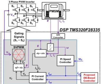
Fig. 4 shows the overall block diagram of the proposed control system for simulation and experiment. A Texas Instruments TMS320F28335 floating-point DSP is used to implement the blocks in the dotted part of Fig. 4. The shaded part of Fig. 4 represents the field-oriented vector control system. In order to obtain digital values of the stator currents (ia, ib) and DC-link voltage (Vdc) we use a
12-bit ADC module with a built-in sample-and-hold circuit. And using an optical encoder, we obtain the rotor position (θ) and motor speed (ω) values. We set the switching period as T = 1/5000[sec] considering the
control performance, and we use a space vector pulse-width modulation (SVPWM) scheme to regulate the phase current input to the PMSM. As shown in Fig. 4, the field-oriented vector control system consists of two control loops : PI speed controller in an outer loop and PI current controller in an inner loop. The input of the proposed d-axis reference current command generator is iqd, the q-axis
reference current command, i.e. the output of the PI speed controller. And the output of the proposed d-axis reference current command generator becomes the d-axis current command of the PI current controller. The following PI gain of the inner loop PI current controller is obtained by [1, 2]
0.4185, 22.24
Pi s I Ii s I
K =Lw = K =Rw = (25)
where ωI = 120π is the bandwidth of the inner loop PI
current controller. Also the following PI gain of the speed controller can be obtained
2 2
1 1
1.414 / 0.0977, / 2.606
Ps I Is I
K = w fr = K =w f r = (26)
leading to the following q-axis reference current command controller
0
0.0977 2.606 t
qd e e
i = - w -
ò
w td (27)The DE parameters to optimize the parameter vector α of the d-axis reference current command generator are set as follows : the parameter dimension Nv = 3, the maximum
generation number Gm = 50, the population size Np = 30,
and the crossover rate Cr = 0.6, and the scaling factor F =
0.9. By using the following performance index
2 2 2 2 2 0 ( 4 4 ) f t e d q d q J=
ò
w +V +V + i + i dt (28) where the weighting factor 4 is used considering Vmax≥2Imax, we obtain the following d-axis reference current
command generator
2 12.2690 0.0081
dd qd
i = - - i (29)
Figs. 5 and 6 show the simulation results of the proposed control system using Matlab/Simulink under the following two conditions :
Load torque TL : 10[N×m]. The desired speed (ωd) : 0
[rad/sec] → 418.879[rad/sec] → -418.879 [rad/sec] → 0[rad/sec].
Load torque TL : 10[N×m] →15[N× m] →10[N× m]. The
desired speed (ωd) : 418.879 [rad/sec].
The case C1 is considered to show the speed transient response, and C2 is intended to illuminate the torque transient response. Fig. 5 shows the transient behaviors by the proposed method when the desired speed changes and the load torque is constant, i.e. ωd = 0 [rad/sec] →
418.879 [rad/sec] → -418.879 [rad/sec] → 0[rad/sec]
Fig. 4. Overall block diagram of the proposed DE-based
Fig. 5. Simulation results by proposed method under C1.
(wd, w, we, iq, and id)
Fig. 6. Simulation results by proposed method under C2.
(wd, w, we, iq, and id)
Fig. 7. Simulation results by conventional method under
C1. (wd, w, we, iq, and id)
Fig. 8. Simulation results by conventional method under
C2. (wd, w, we, iq, and id)
and TL = 10[N×m]. Fig. 6 shows that the torque transient
response when the desired speed is constant and the load torque abruptly changes from 10 to 15 [N×m] and then vice versa, i.e. ωd = 418.879[rad/sec] and TL = 10 [N×m] →15
[N×m] → 10[N×m]. For comparisons, additional simulations have been conducted by using a conventional PI-PI control method where the same PI current controller and PI speed controller are used as the proposed method but the d-axis reference current command is set as idd = 0. Figs.
7 and 8 show the simulation results by the conventional zero idd control method under the conditions C1 and C2,
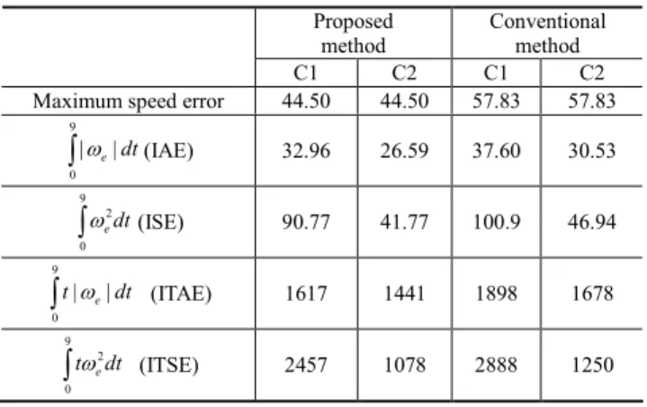
respectively. Figs. 5 through 8 show that the proposed method gives better performances compared to the proposed method. The proposed controller achieves 23 % reduction in maximum speed error, 12 % reduction in IAE, 10 % reduction in ISE, 15 % reduction in ITAE, 15 % reduction in ITSE under C1, and 23 % reduction in maximum speed error, 13 % reduction in IAE, 11 % reduction in ISE, 14 % reduction in ITAE, 14 % reduction in ITSE under C2. Table 1 summarizes the numerical comparisons of the proposed method and the conventional method with respect to the simulation results. The simulation results imply that the common control performance indexes, maximum speed error, IAE, ISE, ITAE, and ITSE can be significantly improved by adding a simple d-axis current
Fig. 9. Experimental test set-up with a TI TMS320F28335
DSP.
Table 1. Numerical comparison between conventional
controller and proposed controller
Proposed method
Conventional method C1 C2 C1 C2 Maximum speed error 44.50 44.50 57.83 57.83
9 0 |we|dt
ò
(IAE) 32.96 26.59 37.60 30.53 9 2 0 edt wò
(ISE) 90.77 41.77 100.9 46.94 9 0 | e| t w dtò
(ITAE) 1617 1441 1898 1678 9 2 0 e twdtò
(ITSE) 2457 1078 2888 1250Fig. 10. Experimental results by proposed method under
C1. (wd, w, we, iq, and id).
Fig. 11. Experimental results by proposed method under
C2. (wd, w, we, iq, and id)
Fig. 12. Experimental results by conventional method
under C1. (wd, w, we, iq, and id)
Fig. 13. Experimental results by conventional method
command generator to a conventional field-oriented vector-controlled PMSM.
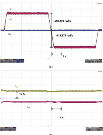
The practicality of the proposed method is also verified through experiments by using an TMS320F28335 DSP-based PMSM prototype system given in Fig. 9. Figs. 10 through 14 show the experimental results about the system responses of the proposed method and the conventional PI-PI control method under the same condition as Figs. 5 through 8, respectively. Figs. 10 (a) to 13 (a) show ωd, ω,
and ωe. Figs. 10 (b) to 13 (b) illustrate id and iq. Figs. 10
and 12 show the experimental results of the proposed method and the conventional PI-PI control method under C1. As can be seen in Figs. 9 and 11 the proposed method yields more than 10 % reduction in maximum speed error under C1. Figs. 11 and 13 illustrate the experimental results of the proposed method and the conventional PI-PI control method under C2. Figs. 11 and 13 show that the proposed controller improves the control performances and it reduces maximum speed error by more than 10 % under C2.
6. Conclusion
This paper has proposed a performance improvement method by using the free degree of freedom in the d-axis current control loop of a field-oriented PMSM. Based on DE approach, an optimal d-axis reference current command generator has been designed such that some useful performance indexes are minimized and/or a tradeoff between conflicting criteria is made. The proposed control algorithm has been implemented on a Texas Instruments TMS320F28335 floating-point DSP. In order to verify the practicality and feasibility of the proposed method, experimental results have been given together with simulation results. It should be noted that the proposed method can be applied to interior PMSMs after some manipulations.
Acknowledgment
This research was supported by Basic Science Research Program through the National Research Foundation of Korea (NRF) funded by the Ministry of Education (No. 2017R1D1A1B03030652). This work was supported by the Korea Institute of Energy Technology Evaluation and Planning(KETEP) and the Ministry of Trade, Industry & Energy(MOTIE) of the Republic of Korea [Grant Number. 20174030201520].
References
[1] H.Z. Jin and J.M. Lee, “An RMRAC current regulator for permanent magnet synchronous motor
based on statistical model interpretation,” IEEE Trans. Ind. Electron., vol. 56, no. 1, pp. 169-177, Jan. 2009. [2] P. Kshirsagar, R. P. Burgos, J. Jang, A. Lidozzit, F.
Wang, D. Boroyevich, and S.-K. Sul, “Implementa-tion and sensorless vector-control design and tuning strategy for SMPM machines in fan-type applications,” IEEE Trans. Industry Appl., vol. 48, no. 1, pp. 2402-2413, 2012.
[3] T.D. Do, H.H. Choi, and J.-W. Jung, “SDRE-based near optimal control system design for PM synchro-nous motor,” IEEE Trans. Ind. Electron., vol. 59, no. 11, pp. 4063-4074, Nov. 2012.
[4] C. Cavallaro, A.O.D. Tommaso, R. Miceli, A. Raciti, G.R. Galluzzo, and M. Trapanese, “Efficiency enhancement of permanent-magnet synchronous motor drives by online loss minimization approaches,” IEEE Trans. Ind. Electron., vol. 52, no. 4, pp. 1153-1160, Aug. 2005.
[5] J.-W. Jung, V.Q. Leu, T.D. Do, E.-K. Kim, and H.H. Choi, “Adaptive PID speed control design for permanent magnet synchronous motor drives,” IEEE Trans. Power Electron., vol. 30, no. 2, pp. 900-908, Feb. 2015.
[6] D.Q. Dang, M.S. Rafaq, H.H. Choi, and J.-W. Jung, “Online parameter estimation technique for adaptive control applications of interior PM synchronous motor drives,” IEEE Trans. Ind. Electron., vol. 63, no. 3, pp. 1438-1449, Mar. 2016.
[7] A. Consoli, G. Scelba, G. Scarcella, and M. Cacciato, “An effective energy-saving scalar control for industrial IPMSM drives,” IEEE Trans. Ind. Electron., vol. 60, no. 9, pp. 3568-3669, Sep. 2013.
[8] Y.-S. Choi, H.H. Choi, and J.-W. Jung, “Feedback linearization direct torque control with reduced torque and flux ripples for IPMSM drives,” IEEE Trans. Power Electron., vol. 31, no. 5, pp. 3728-3737, May 2016.
[9] T.D. Do, H.H. Choi, and J.-W. Jung, “Nonlinear optimal DTC design and stability analysis for interior permanent magnet synchronous motor drives,” IEEE/ASME Trans. Mechatronics, vol. 20, no. 6, pp. 2716-2725, Dec. 2015.
[10] M.P. Kazmierkowski, F. Blaabjerg, and R. Krishnan, Control in Power Electronics : Selected Problems, San Diego, CA : Academic Press, 2002
[11] J. Vesterstrom and R.A. Thomson, “Comparative study of differential evolution, particle swarm optimi-zation, and evolutionary algorithms on numerical benchmark problems,” in Proc. IEEE Congr. Evol. Comput., Jun. 2004, pp. 1980-1987.
[12] S. Rahnamayan, H. R. Tizhoosh, and M.M.A. Salama, “Opposition-based differential evolution,” IEEE Trans. Evol. Comput., vol. 12, no. 1, pp. 64-79, Feb. 2008. [13] Y. Duan and D.M. Ionel, “A review of recent
developments in electrical machine design optimi-zation methods with a permanent-synchronous motor
benchmark study,” IEEE Trans. Ind. Appl., vol. 49, no. 3, pp. 1268-1275, May/Jun. 2013.
[14] S. Das and P.N. Suganthan, “Differential evolution: A survey of the state-of-the-art,” IEEE Trans. Evol. Comput., vol. 15, no. 1, pp. 4-31, Feb. 2011.
[15] S. Morimoto and Y. Takeda, “Expansion of operating limits for permanent magnet motor by current vector control considering inverter capacity,” IEEE Trans. Ind. Appl., vol. 26, no. 5, pp. 866-871, Sep./Oct. 1990.
Hong Min Yun received the B.S. and
M.S. degrees in electrical engineering from Dongguk University, Seoul, Korea, where he is currently working toward the Ph.D. degree at the Division of Electronics and Electrical Engineering. Since 2001, he has been with Auto-mation R&D Center MV Drive Team, LSIS Corporation, Ltd.
Yong Kim received the B.S., M.S.
degrees and Ph.D degrees in Dept. of Electrical Engineering from the Dong-guk Univ. in 1981, 1983 and 1994. Since 1995 He has been a Professor in the Div. of EEE, Dongguk Univ.-Seoul. His teaching and research interests include switch mode power supply and electrical motor drives.
Han Ho Choi received the B.S. degree
in Control and Instrumentation Eng. from SNU, Seoul, Korea, and the M.S. and Ph.D. degree in Electrical Engine-ering from KAIST in 1988, 1990, and 1994, respectively. He is now with the Div. of EEE, Dongguk Univ.-Seoul.