Actively transparent display with enhanced
legibility based on an organic light-emitting
diode and a cholesteric liquid crystal blind panel
Jeongho Yeon,1,2 Tae-Wook Koh,1,2 Hyunsu Cho,1 Jin Chung,1 Seunghyup Yoo,1,3,4 and Jun-Bo Yoon1,4,*
1Department of Electrical Engineering, Korea Advanced Institute of Science and Technology (KAIST), 291
Daehak-ro, Yuseong-gu, Daejeon 305-701, South Korea
2 contributed equally to this work 3 [email protected] 4contributed equally to this work
Abstract: Transparent display is one of the most promising concepts among the next generation information display devices. Nevertheless, conventional transparent displays have two inherent problems: low forward light efficiency due to the light being emitted also in a backward direction; and low legibility due to the visual interruption caused by the light coming from the background. In this work, a cholesteric liquid crystal (Ch-LC) based, actively operational blind panel is combined with transparent organic light-emitting diodes (TR-OLEDs) to recycle the light wasted by backward propagation in transparent displays while blocking the light from behind the display, pursuing both improved forward light efficiency and enhanced image legibility. By tuning the reflectance spectrum of the Ch-LC panel to match the emission spectrum of TR-OLEDs, we achieved luminous efficiency increase by as large as 21% (85%) when the top metal cathode side (the bottom ITO side) of the OLEDs faces the blind panel. Maximum transmittance of the proposed device reached a high value of 60%, successfully demonstrating a new window-like transparent display concept.
©2013 Optical Society of America
OCIS codes: (230.3670) Light-emitting diodes; (230.3720) Liquid-crystal devices. References and links
1. S. I. Park, Y. Xiong, R. H. Kim, P. Elvikis, M. Meitl, D. H. Kim, J. Wu, J. Yoon, C. J. Yu, Z. Liu, Y. Huang, K. C. Hwang, P. Ferreira, X. Li, K. Choquette, and J. A. Rogers, “Printed assemblies of inorganic light-emitting diodes for deformable and semitransparent displays,” Science 325(5943), 977–981 (2009).
2. M. Antikainen, J. Haaranen, J. Honkala, M. Lahonen, V.-M. Liias, A. Pakkala, T. Pikänen, E. Soininen, and R. Törnqvist, “Transparent emissive thin-film electroluminescent display,” SID Symposium Digest of Technical Papers 31, 885–887 (2000).
3. W.-S. Song, Y.-S. Kim, and H. Yang, “Construction of highly transparent plasma display devices using hydrothermally synthesized green-emitting LaPO4:Ce, Tb nanophosphors,” J. Electrochem. Soc. 158(5), J137– J142 (2011).
4. S.-M. Lee, S. H. Oh, and K. C. Choi, “Highly transparent SU-8 photoresist barrier rib for a transparent AC plasma display panel,” J. Display Technol. 7(1), 40–43 (2011).
5. S. M. Lee, D. Kim, D. Y. Jeon, and K. C. Choi, “Nanoplasmon-enhanced transparent plasma display devices,” Small 8(9), 1350–1354 (2012).
6. C.-Y. Lo, O.-H. Huttunen, J. H. Keinänen, J. Petäjä, H. Fujita, and H. Toshiyoshi, “MEMS-controlled paper-like transmissive flexible display,” J. Microelectromech. Syst. 19(2), 410–418 (2010).
7. J. Heikenfeld and A. J. Steckl, “High-transmission electrowetting light valves,” Appl. Phys. Lett. 86(15), 151121 (2005).
8. G. Gu, V. Bulovic, P. E. Burrows, S. R. Forrest, and M. E. Thompson, “Transparent organic light emitting devices,” Appl. Phys. Lett. 68(19), 2606–2608 (1996).
9. G. Parthasarathy, P. E. Burrows, V. Khalfin, V. G. Kozlov, and S. R. Forrest, “A metal-free cathode for organic semiconductor devices,” Appl. Phys. Lett. 72(17), 2138–2140 (1998).
10. B. J. Chen, X. W. Sun, and S. C. Tan, “Transparent organic light-emitting devices with LiF/Mg:Ag cathode,” Opt. Express 13(3), 937–941 (2005).
11. H. Cho, J. M. Choi, and S. Yoo, “Highly transparent organic light-emitting diodes with a metallic top electrode: the dual role of a Cs2CO3 layer,” Opt. Express 19(2), 1113–1121 (2011).
12. J. Lee, S. Hofmann, M. Furno, M. Thomschke, Y. H. Kim, B. Lüssem, and K. Leo, “Influence of organic capping layers on the performance of transparent organic light-emitting diodes,” Opt. Lett. 36(8), 1443–1445 (2011).
13. J. W. Huh, J. Moon, J. W. Lee, D.-H. Cho, J.-W. Shin, J.-H. Han, J. Hwang, C. W. Joo, H. Y. Chu, and J.-I. Lee, “Directed emissive high efficient white transparent organic light emitting diodes with double layered capping layers,” Org. Electron. 13(8), 1386–1391 (2012).
14. W. Kowalsky, P. Görrn, J. Meyer, M. Kröger, H.-H. Johannes, and T. Riedl, “See-through OLED displays,” Proc. SPIE 6486, 64860F, 64860F-14 (2007).
15. J.-H. Lee, X. Zhu, Y.-H. Lin, W. K. Choi, T.-C. Lin, S.-C. Hsu, H.-Y. Lin, and S.-T. Wu, “High ambient-contrast-ratio display using tandem reflective liquid crystal display and organic light-emitting device,” Opt. Express 13(23), 9431–9438 (2005).
16. J.-H. Lee, H. Xianyu, Z. Ge, X. Zhu, Y.-H. Lu, C.-W. Teng, K.-C. Liu, and S.-T. Wu, “Hybrid transflective displays using vertically integrated transparent OLED and reflective LCD,” SID Symposium Digest of Technical Papers 38, 1810–1812 (2007).
17. C.-C. Wu, C.-F. Lin, J.-H. Lee, W.-F. Chang, T.-L. Chiu, and S.-W. Liu, “Fully integration of transflective hybrid device consisting of PSCT and In-cell OLED,” SID Symposium Digest of Technical Papers 42, 1602– 1605 (2011).
18. P. Yeh and C. Gu, Optics of Liquid Crystal Displays (Wiley, 1999).
19. N. Y. Ha, Y. Ohtsuka, S. M. Jeong, S. Nishimura, G. Suzaki, Y. Takanishi, K. Ishikawa, and H. Takezoe, “Fabrication of a simultaneous red-green-blue reflector using single-pitched cholesteric liquid crystals,” Nat. Mater. 7(1), 43–47 (2008).
20. M. Mitov and N. Dessaud, “Going beyond the reflectance limit of cholesteric liquid crystals,” Nat. Mater. 5(5), 361–364 (2006).
21. A. C. Tasolamprou, M. Motov, D. C. Zografopoulos, and E. E. Kriezis, “Theoretical and experimental studies of hyperreflective polymer-network cholesteric liquid crystal structures with helicity inversion,” Opt. Commun. 282(5), 903–907 (2009).
22. R. A. M. Hikmet and H. Kemperman, “Electrically switchable mirrors and optical components made from liquid-crystal gels,” Nature 392(6675), 476–479 (1998).
23. S. Relaix, C. Bourgerette, and M. Mitov, “Broadband reflective liquid crystalline gels due to the ultraviolet light screening made by the liquid crystal,” Appl. Phys. Lett. 89(25), 251907 (2006).
24. M. E. McConney, V. P. Tondiglia, J. M. Hurtubise, T. J. White, and T. J. Bunning, “Photoinduced hyper-reflective cholesteric liquid crystals enabled via surface initiated photopolymerization,” Chem. Commun. (Camb.) 47(1), 505–507 (2011).
1. Introduction
Transparent display is among the highly promising next-generation displays and refers to a display device that is optically clear when it is not under operation but can show images or texts when turned on. Attracted by its various possible applications including smart windows, head-up displays in automobiles, billboards and medical devices, many researchers have contributed to the development of efficient transparent display systems.
So far, various approaches to transparent displays have been reported including transparent inorganic electroluminescent device [1, 2], transparent plasma display panels [3– 5], microelectromechanical/ electrowetting based transmissive displays [6, 7], and transparent organic light emitting diodes (TR-OLEDs) [8–11]. Among such transparent displays, those based on OLEDs are considered as most promising because active layers comprising OLEDs are mostly based on very thin layers of wide-gap materials that are highly transparent. The beneficial characteristics of OLEDs such as self-emissive properties and wide viewing angle are also the factors that make them particularly attractive.
Based on these advantages, many researchers have reported TR-OLEDs with excellent characteristics outrivaling other transparent display competitors. Nevertheless, two significant problems remain unsolved: (i) loss of light that is emitted backwards and (ii) disruption of displayed image caused by light coming from the background. Due to the bi-directional emitting property of TR-OLEDs, a certain portion of light loss is inevitable although the loss fraction could be controlled to some degree by introducing a slight asymmetry in the local transmittance of electrodes [12, 13]. This loss of light accompanies reduced current efficacy and power efficiency in comparison to their opaque equivalent, which has a mirror-like electrode in one side. Disruption of displayed images due to the visual interference of background light can also be a significant problem in securing the legibility and thus delivering correct information; yet its seriousness has rarely been recognized. In this work,
we try to resolve these issues through a novel concept named “actively transparent displays (ATD)” in which TR-OLEDs are combined with an electric blind panel based on cholesteric liquid crystals (Ch-LCs) that can be switched electrically between reflection (‘R’) and transmission (‘T’) states. With the proposed blind panel in the reflection state, the light emitted backwards in the associated TR-OLEDs is recycled so that the brightness of the display can be enhanced, and, at the same time, the background light from behind the display is blocked so that the legibility of the displayed images and texts can be significantly improved.
2. Proposed concept and operation modes
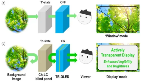
Figure 1 shows the schematic diagram of the proposed actively transparent display based on a TR-OLED integrated with a Ch-LC-based blind panel. When the display is operating in the transparent ‘window mode’ as illustrated in Fig. 1(a), the TR-OLED is turned off while the blind panel behind is switched to the transmission state. In this ‘window mode’, the ambient light can be transmitted through the blind panel and the TR-OLED so that the viewer can see through the display. When the display is operating in the ‘display mode’ as illustrated in Fig. 1(b), the TR-OLED is turned on to display images and texts, while the blind panel is switched to the reflection state. In this ‘display mode,’ a significant portion of ambient light coming in from the backside of the display is blocked (by reflection) by the blind panel, and is not seen by the viewer in the front of the display. Furthermore, the light emitted backwards from the TR-OLED toward the blind panel is reflected at the blind panel and then added to the light emitted in a forward direction. These (i) blocking of ambient light from behind the display and (ii) recycling of light emitted backwards from the TR-OLED enable a transparent display with enhanced image/text legibility and brightness.
Fig. 1. Conceptual illustration of the proposed actively transparent display that consists of a TR-OLED and a Ch-LC-based blind panel that can be electrically switched between transmission (‘T’) state and reflection (‘R’) state. Its representative operational modes are shown: (a) ‘window’ mode and (b) ‘display’ mode.
Another mode of operation (not shown) that is possible with the proposed transparent display is a ‘see-through display mode’ in which the TR-OLED is ON while the blind panel is in the transmission state. In this case, the ambient light from a background object is intentionally overlapped with the displayed images for special purposes. A show window display or some augmented-reality applications might benefit from this operational mode, as was noted by Kowalsky and his associates [14].
It is noteworthy that there were previous works that also involved the combination of a liquid crystal (LC) panel and an OLED [15–17]. However, those works aimed either at improving the contrast ratio of OLED displays [15] or at achieving a hybrid, transflective display in which the LC part becomes a major display element under bright ambient condition while the OLED is mainly responsible under dark ambient condition [16, 17]. The present work also tries to solve similar issues like contrast and legibility, but it differs from those previous approaches in that it addresses those issues particularly from the perspectives of transparent displays.
3. Experiments
In order to demonstrate the suggested transparent display concept, a prototype transparent display was fabricated by combining a Ch-LC blind panel and a TR-OLED with green emission color with an emission peak wavelength near 530 nm. Cholesteric LC (or chiral nematic LC) is a type of LC phase, in which chiral dopant molecules added into nematic LC media form a helically twisted structure along a given symmetrical axis called helical axis. The periodic nature of this helical structure lets a Ch-LC cell act as a Bragg reflector that reflects incident light with the wavelength (reflected) in the following spectral range [18–21]:
o reflected e
pn
pn
(1)where no and ne are the ordinary and extraordinary refractive indices of the LC material,
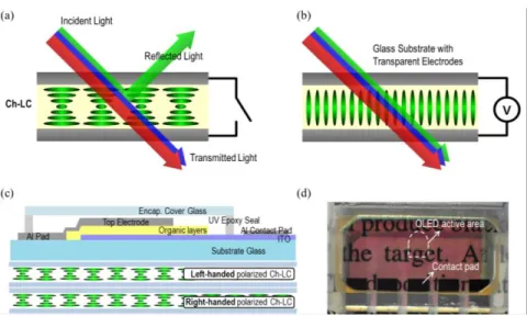
respectively, and p is the helix pitch. In such a case, circularly polarized light with the handedness opposite to that of the helical structure is reflected whereas circularly polarized light with the same handedness is transmitted. The helix pitch p determining the wavelength range of the reflected light depends on the concentration of the chiral dopant molecules [19]. When the reflected light is in the visible wavelength range, the Ch-LC panel would exhibit a certain color according to the spectral range of the light reflected by the planar state Ch-LC, as shown in Fig. 2(a). By applying an electric field across the LC cell, the LC molecules could be aligned along the applied field direction as shown in Fig. 2(b), which is called the homeotropic state. In this state, the Ch-LC panel is optically transparent with little polarization dependence.
To implement a Ch-LC blind panel, two glass substrates coated with indium tin oxide (ITO) thin films were prepared to work as transparent bottom and top electrodes. For homogeneous alignment of the Ch-LC molecules, a layer of polyimide (PI2610, HD Microsystems) was coated on each ITO substrate and cured at 300þC on a hotplate, and followed by the rubbing process. Spherical micro-pearl spacer beads with diameters of 4.75
m were placed on the bottom substrate to secure a vertical gap between two electrodes. An empty cell was fabricated by covering the top substrate onto the bottom substrate while the two substrates are separated by the micro-pearl spacer beads. Then the Ch-LC was prepared by mixing the nematic host material (CH100, HCCH cooperation) and the chiral dopants. Both left- and right-handed Ch-LC cells were prepared and stacked in tandem as shown in Fig. 2(c). Since polarized/unpolarized light can be considered as a coherent/random superposition of left-circularly polarized and right-circularly polarized components, stacking left- and right-handed Ch-LC cells ensures the proposed blind panel to have a high reflectance regardless of the polarization state of incident light when operating in reflection state. (If it is based on a single Ch-LC cell with one specific handedness, the reflectance for unpolarized light cannot be larger than 50%, for example.) Two different types of chiral dopants were used for each polarization handedness (S811 for left-handed circular polarization and R811 for right-handed circular polarization). To match the reflection spectrum of the Ch-LC panel to the emission spectrum of TR-OLEDs, we have carefully tuned the concentration of the chiral dopants in the nematic host to obtain the desired helical pitch [19]. In this way, the reflection band was tunable with a relatively good reproducibility typically within the error bound of 10 nm or less. After injecting each Ch-LC mixtures into the empty cells and stacking the left- and right-handed cells vertically, the Ch-LC blind panel was completed.
Fig. 2. Two different states of the Ch-LC molecules: (a) planar (reflecting) state and (b) homeotropic (transparent) state. (c) Cross-sectional schematic illustration of the proposed transparent display. (d) Close-up picture of the prototype transparent display with a TR-OLED and a Ch-LC-based blind panel. Five finger-shape patterns correspond to the active areas of the individual TR-OLED devices. The TR-OLED is in a configuration of glass/ITO/NPB (50 nm)/Alq3 (50 nm)/ Cs2CO3 (1.5 nm)/Ag (15 nm)/ ZnS (35 nm).
For TR-OLEDs, substrates pre-coated with ITO were cleaned in an ultrasonic bath using soapy water, DI water, acetone and isopropyl alcohol for 20 mins respectively. Cleaned substrates were treated by air plasma (PDC-32G, Harrick Plasma) and immediately brought into a thermal evaporation chamber (HS-1100, Digital Optics & Vacuum). 50 nm of N,N'-Bis(naphthalen-1-yl)-N,N'-bis(phenyl)-benzidine (NPB) as a hole transport layer and 50 nm of tris(8-hydroxy-quinolinato) aluminum (Alq3) as an emission and electron transporting layer
were deposited using thermal evaporation. Subsequently, 1.5 nm of cesium carbonate and 15 nm of Ag were deposited on top as a cathode contact, and finally 35nm of ZnS was deposited as a capping layer [11]. Fabricated devices were analyzed in an N2-filled glovebox using a
Keithley 2400 source meter and a calibrated Si photodiode (FDS-100-CAL, Thorlabs). Emission spectra of each device were obtained using a fiber-optic spectrometer (EPP2000, StellarNet, Inc.). After glass-cap based encapsulation, OLEDs were attached to the Ch-LC blind panel using an UV-curable optical adhesive (NOA61, Norland Products Inc.) for a seamless optical coupling. Cross-sectional schematic illustration of the implemented transparent display is given in Fig. 2(c). A picture of the prototype transparent display is also shown in Fig. 2(d) with the blind panel in the reflection state. Note that the white paper placed behind the prototype appears in a magenta color, due to the blocking and elimination of the green light from the white light reflected from the paper.
4. Results and discussions
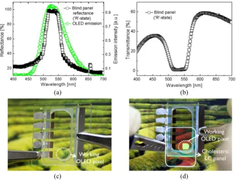
Figure 3(a) shows the reflectance spectrum of the fabricated Ch-LC blind panel together with the emission spectrum of the TR-OLED. Alq3 light-emitting material in the TR-OLED emits
green light with an emission peak at the wavelength of 527 nm and full width half maximum (FWHM) of 87 nm. As could be seen from the reflectance spectrum of the Ch-LC blind panel, the reflection peak was located at the wavelength of 519 nm with FWHM of 60 nm, in a good match to the emission wavelength of the TR-OLED. Since the Ch-LC blind panel reflects light within the designed green wavelength range, it could work as a notch-filter for the incident light. As shown in Fig. 3(b), the transmittance spectrum has a clear notch band, where the incident light is reflected backwards and not transmitted through to the opposite side. It implies that the blind panel cuts off the selected band of the ambient light from behind the display as designed. Thanks to this ambient light rejection, the legibility of a displayed
image can be significantly enhanced. This benefit can be easily confirmed in the examples shown in Figs. 3(c) and 3(d). Although the TR-OLED in Figs. 3(c) and 3(d) is operating at the same brightness level, the working pixel shown in Fig. 3(c) looks obscure due to the green ambient light reflected from the picture placed behind our transparent display. When such ambient light is shut off by the Ch-LC blind panel, the green, finger-shaped image from the TR-OLED is more clearly distinguished, confirming the enhanced legibility of the proposed transparent display.
Fig. 3. Optical properties of the TR-OLED and the Ch-LC blind panel. (a) Emission spectrum of the TR-OLED and the reflection spectrum of the blind panel. (b) Green wavelength cut-off observed in the transmittance spectrum of the Ch-LC blind panel. (c) Obscure transparent green TR-OLED pixel due to the light from the background image (d) Lucid green TR-OLED pixel with improved legibility assisted by the Ch-LC blind panel. TR-OLED pixel is operating at the same luminance level in in both (c) and (d).
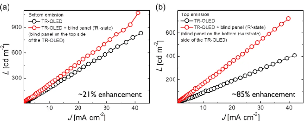
To verify the luminance enhancement of the TR-OLED assisted by the reflection from the Ch-LC blind panel, we have measured the forward luminance of the transparent display while varying the current density within the TR-OLED. Since we could attach the Ch-LC blind panel to the top side of the TR-OLED (on the encapsulation cover glass) or to the bottom side of the TR-OLED (directly on the glass substrate of the TR-OLED), we have analyzed luminous efficacy of our transparent display for both cases. Figure 4(a) exhibits the forward luminance (L) - current density (J) characteristics of the TR-OLED before/after the Ch-LC blind panel is applied to the top side of the TR-OLED. While the TR-OLED by itself exhibited a bottom-direction luminous efficacy of 2.02 cd A1, our prototype transparent display with the Ch-LC blind panel assistance exhibited a higher luminous efficacy of 2.44 cd A1 which corresponds to a relative enhancement of 21%. This indicates that the Ch-LC blind panel indeed contributed to the light efficiency enhancement of the TR-OLED by recycling the light emitted backwards as intended. In the case of the bottom (substrate) side attachment, the top-direction luminous efficacy was increased from 0.97 cd A1 to 1.79 cd A1 which corresponds to a relative enhancement of 85% (Fig. 4(b)). Since the top/bottom side emission intensities of the TR-OLED itself were asymmetric to be around 1:2.1, enhancement of the luminous efficacy by attaching the Ch-LC blind panel was greater for the bottom side-attached case than the top side-side-attached case, while the overall transmittance did not change.
Fig. 4. Luminance (L) versus current density (J) curves of the fabricated TR-OLED before/after attaching the blind panel to the (a) top and (b) bottom side of the TR-OLED.
We have measured the overall transmittance spectra of the transparent display including the TR-OLED and the Ch-LC blind panel during the ‘window mode’ operation as well as that of the TR-OLED itself. While the peak transmittance of the TR-OLED was 81.6% at 578 nm, the peak transmittance of the prototype transparent display was 63%. The overall transmittance of the transparent display was approximately between 65% ~78% of that of the TR-OLED due to the transmittance decrease by the Ch-LC blind panel itself, as shown in Fig. 5. Note that the proposed transparent display, despite some transmittance loss by the combination, exhibits average transmittance of 56% in the visible spectral region.
Fig. 5. Transmittance spectrum of the TR-OLED with/without the Ch-LC blind panel, measured during the ‘window mode’ operation.
Although we have implemented our prototype transparent display only for a green color, this concept could be expanded to the whole visible wavelength band. By stacking the Ch-LC blind panels with reflectance wavelength ranges spanning three primary colors, a ‘white’ blind panel could be easily implemented. However, decrease of transmittance due to the repeated stacking of panels could be a problem in this approach. Therefore, introducing a pitch gradation to the Ch-LC cells could be an alternative option to cover the whole visible wavelength range, as demonstrated by Hikmet and Kemperman [22]. By adding an ultraviolet (UV) curable LC polymer to the Ch-LC mixture and irradiating UV light on it, helical pitch gradation is known to be spontaneously induced within the Ch-LC cells along the vertical direction [22–24]. This pitch gradation could widen the reflectance wavelength band; shorter pitch molecules could reflect shorter wavelength light, while longer pitch molecules could reflect longer wavelength light. By applying this approach, the proposed actively transparent
display could be expanded to a full color transparent display with little sacrifice in the overall transmittance that could result from the repeated stacking of the Ch-LC blind panels.
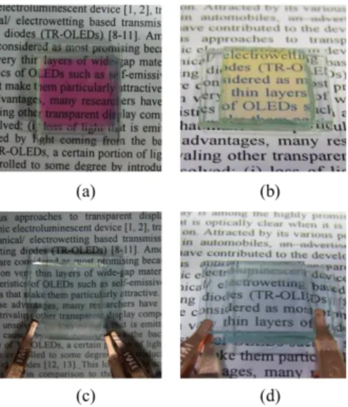
The viewing angle dependence of a display device is also an important performance specification to consider. Since the proposed Ch-LC blind panel is essentially a Bragg reflector, the peak reflection wavelength for the Ch-LC blind panel is blue-shifted as the viewing angle increases. Figures 6(a) and 6(b) show the photographs of the Ch-LC blind panel in the reflection state taken at the normal direction and at a tilted angle, respectively. The panel looks magenta when observed from the normal direction due to the elimination of green band from the white light reflected from the paper. On the other hand, it looks yellow when observed from a tilted angle. This is consistent with the notion of blue-shifted reflection band in an off-normal direction as the white light minus the blue component results in yellow color. This angular dependency of the reflection band of the Ch-LC blind panel is expected to yield a decrease in efficacy enhancement in the proposed display when viewed from an off-normal direction. Nevertheless, this viewing angle dependence could be lessened by realizing the broadband Ch-LC blind panel covering the whole visible spectral range as described above. When the Ch-LC blind panel was in the transmission state, no particular viewing-angle dependency was observed as shown in Figs. 6(c) and 6(d). This makes sense as the periodicity corresponding to a Bragg reflector no longer holds in transmission state, where molecules within the Ch-LC blind panel are homeotropically aligned.
Fig. 6. (a), (b) The Ch-LC blind panel in reflection state: (a) when observed from the normal direction (the panel designed for green reflection band); (b) when observed from a tilted angle (blue-shifted reflection band). (c), (d) The Ch-LC blind panel in transmission state: (c) when observed from the normal direction; (d) when observed from a tilted angle.
5. Conclusion
In this work we demonstrated a novel actively transparent display (ATD) concept in which an actively operational cholesteric LC (Ch-LC) blind panel is combined with a transparent OLED (TR-OLED) device. With the Ch-LC blind panel in reflection state, light emitted backwards from the TR-OLED, which would otherwise be wasted, can be recycled and added to the forward-emitting light. Thanks to this recycling, luminous efficacy of the TR-OLED was shown to increase by 21% for the bottom emission case, and up to 85% for the top emission case. In addition, the clear band-stop performance of the Ch-LC blind panel in the visible range proved to efficiently block the ambient light from behind the display, and thus significantly enhance the legibility of displayed images or texts. When the Ch-LC blind panel
was set at transmission state, our prototype transparent display looks like a clear window with the average transmittance of 56% throughout the visible spectral range.
As the proposed actively transparent display concept successfully overcomes the two major problems of the conventional transparent displays - low luminous efficacy caused by the waste of light emitted backwards and the low image/text legibility due to the ambient light from behind the display, we believe our approach could contribute to major advances in the fields of transparent display.
Acknowledgments
This work was supported by the Industrial Strategic technology development program (10035573, “Development of selective transparent displays through innovation in device structure”) funded by the Ministry of Knowledge Economy (MKE), Korea. First two authors (J. Yeon and T. -W. Koh) contributed equally to this work.