NOMENCLATURE
a
= acceleration of contact plate aeroF
= aerodynamic lifting force conF
= contact force of contact plate conF
= average force of contact plate spF
= spring force below contact plate spF
= average spring force below contact platek
= coefficient of aerodynamic lifting force cpm
= mass of contact plateV
= train velocity1. INTRODUCTION
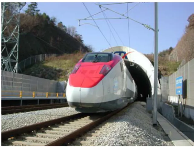
KTX(Korea Train eXpress) begins commercial service on April 1, 2004. Korea becomes the fifth country to operate high speed railway system in the world. At the same time, KHST(Korea High Speed Train) succeeded in trial running on the test track at the speed of 300km/h. KHST shown in Fig. 1 has been constructed by home grown technologies for 7 years. All of the core systems of KHST has been developed by domestic research institutes and related companies. Pantograph is the one of the core systems developed by domestic technology. The pantograph of electric power car collects current from the catenary system and supplies electric power to the transformer and the main traction system. Pantograph should follow the catenary without separation for continuous current collection. Sufficient contact force is necessary for the contact plate of pantograph not to separate from the catenary system. Separation of the contact plate of pantograph causes arc generation and gives damages to the catenary system. Separation also deteriorates the quality of the collected current. On the contrary, excessive contact force causes rapid erosion of the contact wire of catenary. Since the pantograph of high speed train is in high speed air flow field, significant lifting force is added to the contact force. So, an upper limit of contact force is regulated by the standard or the guidelines[1]. Control of contact force is important for current
collection performance and maintenance of the catenary system.
A Study on the Measurement of Contact Force of Pantograph on High Speed Train
Sung-Il Seo*, Yong-Hyun Cho**, Jin-Yong Mok***, Choon-Soo Park*** and Ki-Hwan Kim**** Conventional Rail Emgineering Department, Korea Railroad Research Institute, Gyeonggi, Korea (Tel:+82-31-460-5623; E-mail:[email protected])
** Electrical & Signal Research Department, Korea Railroad Research Institute
** High Speed Rail Engineering Department, Korea Railroad Research Institute, Gyeonggi, Korea
Abstract: Appropriate upward force is crucial for the pantograph on high speed train to collect current from the catenery system without separation. However, at high speed, large aerodynamic lifting force is generated by the contact plate and the arms of pantograph, which may cause wear of the contact wire. In this study, to confirm the interface performance of the pantograph on Korea High Speed Train, a method to measure the contact force of the pantograph was proposed and the related measurement system was developed. The forces acting on the pantograph were clarified and a procedure to calculate the aerodynamic lifting force was proposed. A special device was invented and applied to measure the lifting force. Measured contact forces were displayed by the developed system and evaluated according to the criteria. Countermeasures were also taken to reduce the contact force based on the results.
Keywords: Catenary system, Contact force, High speed train, Pantograph
In this study, to evaluate the interface performance of the domestic pantograph on Korea High Speed Train and to provide a basis to control the contact force, a contact force measurement system is developed. The forces acting on the pantograph are classified and the aerodynamic lifting force is investigated. A method to measure the forces are proposed and verified. Based on the measured results, countermeasures to reduce the contact force are conceived.
Figure 1 Korea High Speed Train
2. OUTLINE OF PANTOGRAPH
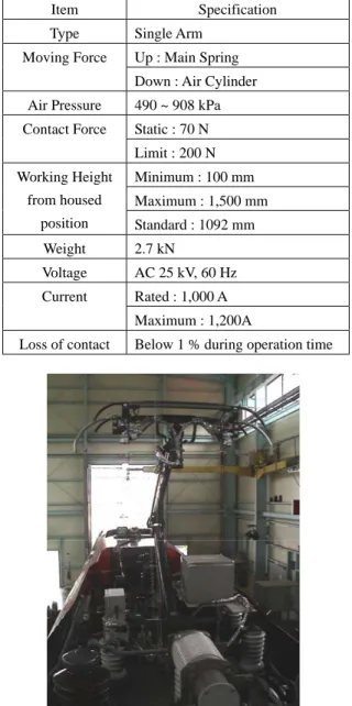
The pantograph on Korea High Speed Train is shown in Fig. 2. The pantograph of Korea High Speed Train collects the current of AC 25kV and 60 Hz from the catenary and supplies electric power to main transformers. The pantograph is single armed type. To reduce aerodynamic noise and weight, the structure is designed simple and the outer diameter and thickness of members are designed optimum. To prevent separation from the catenary, the second suspension system is installed below the contact plate. The main characteristics of the pantograph are shown in Table 1[1].
Table 1 Major specification of pantograph on Korea High Speed Train
Item Specification Type Single Arm
Up : Main Spring Moving Force
Down : Air Cylinder Air Pressure 490 ~ 908 kPa
Static : 70 N Contact Force Limit : 200 N Minimum : 100 mm Maximum : 1,500 mm Working Height from housed position Standard : 1092 mm Weight 2.7 kN Voltage AC 25 kV, 60 Hz Rated : 1,000 A Current Maximum : 1,200A
Loss of contact Below 1 % during operation time
Figure 2 Pantograph on Korea High Speed Train
FORCES ON PANTOGRAPH
The acting forces on the pantograph are shown in Figure 3. Each member of the pantograph is subjected to aerodynamic load and static upward force. Since we are concerned with the contact plate, the secondary spring below the contact plate is cut out and the force equilibrium condition is expressed by Eq. (1).
a
m
F
F
F
con+
sp+
aero=
cp−
(1) Fc, Contact ForceFa, Aerodynamic Lifting Force
Fst, Static Force Fs, Spring Force Contact Plate Horn Acceleration Motion of Contact Plate
Figure 3 Equilibrium condition of pan-head
The contact force with the catenary is the sum of spring force, aerodynamic lifting force and inertia force. The contact plate of pantograph is on the secondary suspension in the guide horn to follow the catenary smoothly. Initial static upward force is supplied by the primary springs on the roof of the power car and transferred to the secondary suspension. It is controlled by the supplied air from the auxiliary compressor. The pantograph in high speed flow field is subjected to aerodynamic lifting force. Contact plate, lifting plate, horn frame and arms generate aerodynamic lifting force. Inertia force is induced by the accelerating motion of the contact plate. It is very difficult to measure directly the contact force during service running because measuring device is subjected to the danger of high voltage power. For this reason, in most cases
aero con
F
F
−
was measured and the aerodynamic lifting force of the contact plate was neglected[2]. However, at high speed the aerodynamic lifting force can’t be neglected, because it is proportional velocity square. To measure the contact force accurately, correct estimation of the aerodynamic force is necessary.Because the time average of the inertia force becomes zero, it doesn’t contribute to the mean contact force. As shown in Eq. (1), the spring force of the secondary suspension becomes average contact force subtracting the aerodynamic force. If the instantaneous inertia force is needed, it can be calculated by adding the measured acceleration times mass of the contact plate to the spring force.
PRINCIPLE OF CONTACT FORCE
MEASUREMENT
During service running, the spring force can be measured by inserting a load cell under the secondary suspension. As mentioned above, the aerodynamic lifting force should be added so that accurate contact force may be measured. Since direct measurement of the aerodynamic lifting force is not possible during service running on account of safety, it is measured indirectly and corrected for contact force.
It is well known that aerodynamic lifting force is proportional to velocity square. Taking into account that average inertia force is zero, Eq. (1) can be expressed by the following equation.
2 sp
con
F
V
F
=
+
k ( 2 ) If the contact force and the spring force are measured simultaneously while the train is running, the proportional coefficient of the aerodynamic lifting force can be calculated by the following equation.2 sp con V F F k= − (3)
To measure the contact force and the spring force simultaneously, a temporary special device is needed. During running, KHST collects current only through the backward pantograph. The forward pantograph is for emergency mode. The design specification prohibits simultaneous current collection by the two pantographs for safety because short circuit may be created on the high voltage line. So, one pantograph is raised only for measurement and the other
pantograph is raised for current collection. For this purpose, the forward pantograph is constrained temporarily by a wire rope as shown in Figs. 4~5. The wire rope is used not only to transfer the upward force of the contact plate but also to prevent the contact plate from touching the catenary. The wire rope is connected to the load cell on the roof which senses the upward force of the contact plate. At the same time, the spring force of the secondary suspension is also measured. The difference between the upward force and the spring force is the aerodynamic lifting force of the contact plate as shown in Eq. (2). The proportional coefficient of aerodynamic lifting force is calculated by Eq. (3). Once the upward force is measured, the wire rope is removed and emergency mode to raise the forward pantograph is cancelled.
Figure 4 Connecting wire to transfer lifting force
Figure 5 Load cell to measure lifting force
MEASUREMENT SYSTEM
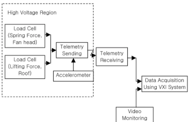
The configuration of the measurement system is shown in Fig. 6. The system is divided into sensors, sending telemetry, receiving telemetry and data processing part. Sensors such as load cell and accelerometer detect variation of physical quantity and generate signals, which are transmitted to the sending telemetry by wire. The sending telemetry collects the signals through each channel and transmits them by wireless to the receiving telemetry on the cabin of the trailer. Transmission by wireless is for safeguard of the test persons and the equipments on the cabin. The received signals are processed by the main computer connected with the receiving telemetry. VXI system is used for data processing. Fig. 7 shows the data processing system.
Load Cell (Lifting Force, Roof) Telemetry Sending Telemetry Receiving Video Monitoring Data Acquisition Using VXI System High Voltage Region
Load Cell (Spring Force,
Fan head)
Accelerometer
Figure 6 Configuration of contact force measurement system
Figure 7 Data processing system
Load cells for spring force measurement are installed below the suspension springs as shown in Fig. 8 and load cells for total upward force measurement are installed on the roof as shown in Fig. 5. Accelerometers are attached below the cross beam of pantograph head as shown in Fig. 9. Train velocity and kilometer post are measured by the speed sensor on the wheel.
Figure 9 Accelerometers under cross beam
MEASURED REULTS AND EVALUATION
During test running, the received signals from the telemetry are converted to the text files by software and are displayed in real time on the monitor. All the data are recorded in the hard disk and useful information is extracted and shown by analysis software . The upward force of the contact plate is shown in Fig. 10. It reveals that the upward force increases in proportion to velocity square. The upward force and the spring force are shown in Fig. 11. The aerodynamic lifting force of the contact plate is given by the difference of the upward force and the spring force. The calculated aerodynamic lifting force coefficient is expressed by the following Eq. (4).)
(N/km
000545
.
0
k
=
2 (4) Force(N) Velocity(km/h) Time(sec) Train Velocity Upward Force of forward Contact PlateUpward Force of Backward Contact Plate Total Upward Force
Figure 10 Measured results of upward force of contact plate Once the aerodynamic lifting force coefficient is found, the aerodynamic force of the contact plate is calculated and automatically included during data processing. The corrected contact force is recorded and displayed on the monitor.
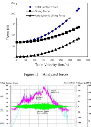
The contact force becomes larger as the train velocity increases. Because large contact force accelerates wear of the contact wire, it should be controlled in a limit. Normal limit of contact force is 200 N as shown Table 1. The measured results showed that the contact force is below 200 N until the train reaches the speed of 270km/h. When the train speed exceeded 270km/h, the contact force was above 200N. To prevent excessive wear of the contact wire, the contact force should be reduced to 200N in the velocity range above 270km/h. A plate is attached on the horn to control the lifting force. To reduce the lifting force, the lifting force control plate was changed into a smaller one. The length of the plate couldn’t be reduced because of fitting location. Instead, the breadth and thickness of the plate was reduced. After the lifting force control plate was changed, the contact plate was reduced below 200 N as
shown in Fig. 12. 0 50 100 150 200 250 0 50 100 150 200 250 300 350 400 Train Velocity (km/h) Force (N) .
Total Contact Force Spring Force
Aerodynamic Lifting Force
Figure 11 Analyzed forces
Figure 12 Measured contact force after modification of lifting force
SUMMARY AND CONCLUSION
Korea High Speed Train is one of the most excellent achievements in the railway research fields of Korea. In this study, to confirm the interface performance of the pantograph on Korea High Speed Train, a method to measure the contact force of the pantograph was proposed and the related measurement system was developed. A special device and procedure was invented and applied to measure the contact force. The hardware system to process the signal data was also developed. The hardware system is composed of sensors and signal sending part, signal receiving part and data processing computer. The measured results showed the importance of the aerodynamic lifting force at the high speed range. Above the speed of 270 km/h, the contact force exceeded the limit which is regulated to protect the contact wire. The contact force was lowered by the change of the lifting force control plate. Owing to the developed system, the interface performance of the pantograph was confirmed.
REFERENCE
[1] K. H. Kim, G. R. Jung and B. S. Lee, 2002, System
Specification for G7 Korean High Speed Train, Korea
Railroad Research Institute, pp. 51∼53.
[2] M. Ikeda and T. Usuda, 2000, "Study on the Method of Measuring the Contact Force between Pantograph and Contact Wire", RTRI Report, Vol. 14, No. 6, pp. 7∼12.
Mok, 2003, “Test and Evaluation of the Pantograph for Korea High Speed Train”, Journal of the Korean Society
for Railway, Vol. 6, No. 2, pp. 94~99.
[4] Alstom, 2001, Qualification Test Procedure Trainset Pantograph Test, Korea High Speed Rail, pp. 28∼30. [5] G. Y. Choi and S. W. Kim, 2002, "G7 Development of
technology for test and evaluation of performance of Korean High Speed Train", Report No. 1-II-1-0-1, Korea Railroad Research Institute.