ICCAS2005 June 2-5, KINTEX, Gyeonggi-Do, Korea
1. INTRODUCTION
In the navigation research of a mobile robot, obstacle avoidance is a basic skill that can make the robot move purposely and safely in an environment even with some known or unknown obstacles. Although that function seems easy to a human being, and its application can be found in some robots, it is still limited to some specified applications and some special hardware. Moreover, many problems still should be further explored before a mobile robot can move freely in such environment. These problems mainly include: the unavoidable slip; the drift errors of sensors; the three dimensional geometry of an obstacle and its relative position or speed to the robot[1, 3 5]. In a word, they are the robot’s
self-location and the geometric information of that obstacle. At first, the robot must have the functions to detect that obstacle and get its geometric information before avoidance. More researchers have explored such problems in this field. One general solution is the sensors based motion planning method, in which information about obstacles is assumed to be obtained from on-line sensors without previous detailed given plan. It is helpful for the navigation in unstructured environments and avoidance of unexpected obstacles, and its navigation strategies are simple. But it will be easily to often make robot miss its original goal and reach its target uneffeciently. Especially, it will make a long distance navigation inefficient or even fail. Another problem is: how to make sure the obstacle detection are robust under any conditions.
The second problem is the mobile robot’s self-location. Because of the unavoidable slip and drift errors of sensors, it is difficult to realize accurately self-location especially after a long distance navigation. However, in any obstacle avoidance we have to consider the robot’s self-location and its position relative to the obstacle. It will make the obstacle avoidance success or not. The perceptual landmark is an effective solution to that problem. But it was generally used as self-location adjustment in some local areas. Because the obstacles will appear any spot along its moving trace, sometimes they maybe influence the detection of the landmark, it makes self-location more difficult[2,3,4].
On the other hand, all control strategies were designed based on the robot’s physical structure and behavior abilities.
Their output actions were planned from the mapping information of sensor’s feedback. Till now it is nearly impossible to consider all practical environment settings. That means we can not design a robot with enough sensors to get all necessary information. Furthermore, the sensor’s error can not be avoided and some information processing algorithms of sensors are still be explored. Therefore, the only sensors based motion planning strategies are not comprehensive. It is necessary to build a flexible system for some special applications. And it will be helpful for future applications to realize obstacle avoidance only with some simple hardware and algorithms.
In view of above problems, we explored a mobile robot’s navigation with obstacle avoidance in this paper. Our robot has two CCD video cameras, but only one was used in our research. It has six supersonic sensors for obstacle detection which can detect objects less than 0.5 meter in its vertical direction. On the front side, two supersonic sensors were set on each end respectively. The same arrangement was done on the left and right sides. In order to realize reliable self-location in its navigation, we design a continuous visual landmark and put it on the floor as the robot’s moving trace. Thus the obstacle avoidance becomes how to avoid obstacles on the guideline. Certainly, we also consider the obstacle near the guideline.
With the continuous guideline, the robot can adjust its relative position gradually and make the navigation more efficiently even if there is obstacle avoidance. At the same time it is helpful for obstacle detection. This is because parts of the guideline will disappear if there are something on the guideline. And if the obstacle is near to the guideline, the relative position can be determined by the supersonic sensor and CCD video camera together. Most of important, compared with other sersors based obstacle avoidance, the robot will not miss its navigation direction after the obstacle avoidance because of the guideline setting. Because the guideline will occupy some fixed areas in the navigation space, the obstacle avoidance has to be carried out in the residual areas. This makes some bigger obstacle avoidance impossible.
In the following sections, the details will be given for the obstacle avoidance for our mobile robot.
Study on the Effective Solution of Obstacle Avoidance Strategy
for a Mobile Robot in the Guideline Navigation
Jiwu Wang
1Masanori Sugisaka
1,21Department of Electrical and Electronics Engineering, Oita University, Oita 870-1192, Japan
2The Institute of Physical and Chemical Research (RIKEN) at Nagoya, Anagahora, Shimoshidami, Moriyama-ku Nagoya,
463-0003, Japan
(Tel : +81-97-554 -7831; E-mail: [email protected], [email protected])
Abstract: Obstacle avoidance is a basic skill to make a mobile robot move effectively and safely even in any arbitrarily given
environment. Because of the difficulty of self-location caused by unavoidable slip and drift errors of sensors and effective detection of any encountered obstacle, only finite and simple obstacle avoidance strategies can be carried out. In this paper we mainly explored how to make a robot perform effectively obstacle detection and avoidance in the guideline navigation with one CCD video camera and some supersonic sensors. Making use of the specially designed guideline, the detection and calculation of the geometric dimensions of the encountered obstacle became simpler. And possible avoidance strategies appropriate to our navigation were studied and the simulations results were given.
Keywords: Obstacle avoidance, Mobile robot, Image processing, Guideline navigation
ICCAS2005 June 2-5, KINTEX, Gyeonggi-Do, Korea
2. OBSTACLE DETECTION
In order to carry out obstacle avoidance effectively, the robot must detect that obstacle firstly. The best way is to obtain the three dimensional geometric information of that obstacle and its distance to the robot. Till now, it is possible to get such data by special hardware settings. But it is still more difficult to directly apply that technique in practical long distance navigation at higher speed. This is mainly because its efficiency and accuracy sometimes are not satisfied.
In this paper, we detect the obstacle and determine its necessary dimensions for avoidance by the cooperation of a CCD video camera and six supersonic sensors. Here with a CCD video camera we indirectly detect the obstacle and then determine its necessary dimensions by corresponding supersonic sensors. With the CCD vide camera, the robot can find the obstacle a little far from the robot, and the supersonic sensors can find the obstacle near to the robot.
In order to make obstacle detection more robust, the guideline must be extracted effectively under various lighting conditions in our research. Thus the obstacle will be judged indirectly when some parts of the guideline disappeared or the guideline became discontinuous. Because the robot will gradually adjust its position relative to the guideline, some low level image processing technique was used for perceptual landmarks extraction. It can effectively save the time for image processing, but sometimes detection was not so robust under different lighting conditions.
In this paper gradient runs based target detection technique
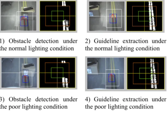
was used for guideline extraction. As we know, there are the gradients everywhere in an image. If we use the guideline with strong color contrast with the floor, it is easy to extract it even under poor lighting conditions. The experiments under different lighting also gave the same results in figure 1. In the figure 1, we can find some parts of the extracted guideline missed when there is a box on the guideline no mater that it is under the normal or poor lighting condition. In this processes it is important to have a robust image processing for guideline extraction. Otherwise, it is difficult to make obstacle detection reliable. Moreover, the robot can only find the obstacle, but it does not know the dimensions and definite distance to the obstacle.
Till now, it is not possible to develop the direct and effective image processing for various obstacle detection. That means we can not calculate the necessary geometric dimensions of the encountered obstacles. Here the supersonic sensors were used to detect the width and length of the obstacles. In the front side of the robot, the distance between the two supersonic sensors is nearly the same as the width of the robot. If both of the two supersonic sensors detect obstacle, the width of that obstacle will be larger than the width of the robot. Because the residual space is smaller for avoidance, the robot can not avoid that obstacle. Therefore, now the robot is only possible to avoid some obstacle when only one of the frontal supersonic sensors detected obstacle. The distance between two supersonic sensors on the left or right side is equal to the length of the robot. Thus when the robot passes the obstacle, it will start when the first sensor detected the
1) Obstacle detection under
the normal lighting condition 2) Guideline extraction under the normal lighting condition
3) Obstacle detection under the poor lighting condition
4) Guideline extraction under the poor lighting condition Figure 1 Illustration on the comparison of the obstacle detection
under different lighting conditions
Figure 2 Illustration of the tele-control through Internet
ICCAS2005 June 2-5, KINTEX, Gyeonggi-Do, Korea
obstacle and end when two sensors can not detect the obstacle.
Those data now are enough for our obstacle avoidance strategies.
As for some complex cases, the robot can not detect the obstacle effectively with present algorithms, the robot will send the instant captured images to the supervisor. The supervisor will send necessary commands to the robot. Then the robot will avoid those obstacles based on the human being’s experience. The communication process is realized through the networks. Figure 2 is a simple explanation of that communication between the robot and a supervisor. By this means, it seems that we can solve all problems for the navigation of a robot. The efficiency of the communication should be considered. Therefore, it can only be used as an auxiliary tool in the situation that we can not find appropriate algorithm at present stage. It can also be applied to the fields that are not sensitive to the rate of the image transmission.
3. SIMULATION
The robot will move along the guideline on the floor. When it carries on the obstacle avoidance, it should consider not only the efficiency of the obstacle detection but also the space used for the obstacle avoidance. For our mobile robot, it can generally realize three categories of simple obstacle avoidance in figure 3. In figure 3, the two blue lines represent the guideline, the yellow line is the obstacle avoidance moving trace, the red triangle represents one obstacle and the green rectangle represents the mobile robot. With the rectangle trace, the robot can perform any obstacle avoidance in the given
space. However, when we consider the efficiency, the robot can perform triangle trace for the smaller obstacle and trapezoid trace for the bigger obstacle.
Because of the errors of sensors and the efficiency of navigation, we only develop the simple obstacle avoidance strategy in our applications.
When we developed the navigation system for our mobile robot, we also developed a simulation system with the same control theory and parameters used in the practical applications. Although it is impossible to consider all factors of practical applications in the simulation system, some developed algorithms can be tested before practical experiments and it can give some necessary simulation results and optimization parameters for some specified working conditions.
In figure 4, it is an illustration for obstacle avoidance in a simulation. The black point represents the obstacle, the green line is the obstacle avoidance trace, the yellow line is the specified navigation trace, the red point represents target point, the blue circle represents the robot and its blue line is robot’s frontal side. The moving sequence was the same as the marked number sequence in the figure. When the robot performs the obstacle avoidance, it tries to find the short trace for obstacle avoidance. In figure 4, we only gave the case for triangle obstacle avoidance trace.
4. CONCLUSIONS
The real time obstacle detection and avoidance was carried out for our mobile robot in the guideline navigation by using a
1) Rectangle 2) Triangle 3) Trapezoid Figure 3 An illustration of the strategies of the obstacle avoidance
1) 2) 3)
4) 5) 6) Figure 4 Simulation on the curve navigation with obstacle avoidance
ICCAS2005 June 2-5, KINTEX, Gyeonggi-Do, Korea
CCD video camera and six supersonic sensors. By making use
of the guideline to adjust robot’s self-location, the obstacle detection became more reliable and simpler if the guideline can be extracted robustly under various lighting conditions. Considering the errors of sensors and the difficulty of the determination of three dimensional geometric information of the encountered obstacle, it is more appropriate to build a flexible obstalce avoidance strategy in the practical application. The experiment results showed the reliability of the obstacle detection method even under the poor lighting condition. And the simulation of the navigation with obstacle avoidance showed how the robot avoided an encountered obstacle.
REFERENCES
[1] Masanori Sugisaka, Xin Wang, Ju-Jung Lee, Intelligent control with new image processing strategy for a mobile vehicle, Artificial life robotics, 1998: 113-118.
[2] J. Wang, M. Sugisaka, Study on a color based target detection technique”, Proceedings of 7-th international symposium in artificial life and robotics (AROB 7-th’02), B-Con Plaza, Beppu, Oita, Japan, Jan. 16-18 : 532-536
[3] J. Wang, M. Sugisaka, Study on visual-based indoor navigation for an alife mobile robot,ICSEng2002, Las Vegas, USA, 2002, August 6-8 : 390-396.
[4] J. Wang, M. Sugisaka, Improvement on the image processing for an automous mobile robot with an intelligent control system, International conference on control, automation and system (ICCAS2001), 2001: 437-440
[5] Seydou Soumare, Akihisa Ohya, etc. Real-time obstacle avoidance by an autonomous mobile robot using an active vision sensor and a vertically emitted laser slit, http://www.roboken.esys.tsukuba.ac.jp/
~ohya/pdf/IAS2002-SUM.pdf
[6] J. Borenstein, Real-time obstacle avoidance for fast mobile robots, IEEE Trans. Syst. Man Cybern., 1989, vol. 19: 1179-1187
[7] A. Ohya, A. Kosaka and A.Kak, Vision-based navigation by a mobile robot with obstacle avoidance using single-camera vision and ultrasonic sensing, IEEE Trans. Robot. Automat., 1998, vol.14: 969-978
[8] K. Yoshida, S.Yokota and I. Watabe, A real-time motion stereo vision based on brightness difference, Proc. IEEE/RSJ IROS 99, 1999, vol1: 77-82